Gigabyte Z690 Aorus Master review
99points
Gigabyte Z690 Aorus Master
Gigabyte Z690 Aorus Master
Why is Gigabyte Z690 Aorus Master better than the average?
- RAM speed?
4800MHzvs2657.11MHz - Overclocked RAM speed?
6400MHzvs4229.73MHz - Fan headers?
10vs4.84 - USB 3.2 Gen 1 ports (USB-A)?
4vs3.6 - SATA 3 connectors?
6vs5.53 - Maximum memory amount?
128GBvs81.12GB - USB 3.0 ports (through expansion)?
4vs2.53 - Signal-to-Noise ratio (DAC)?
120dBvs109.68dB
Which are the most popular comparisons?
Gigabyte Z690 Aorus Master
vs
Asus ROG Maximus Z690 Hero
Gigabyte Z690 Aorus Master
vs
Gigabyte Z690 Aorus Pro
Gigabyte Z690 Aorus Master
vs
Gigabyte Z690 Aorus Ultra
Gigabyte Z690 Aorus Master
vs
Gigabyte Z690 Aorus Xtreme
Gigabyte Z690 Aorus Master
vs
Gigabyte Aorus Z790 Master
Gigabyte Z690 Aorus Master
vs
Gigabyte Z690 Aero D
Gigabyte Z690 Aorus Master
vs
MSI MPG Z690 Carbon WiFi
Gigabyte Z690 Aorus Master
vs
Asus ROG Strix Z690-F Gaming WiFi
Gigabyte Z690 Aorus Master
vs
Asus ProArt Z690-Creator WiFi
Gigabyte Z690 Aorus Master
vs
MSI MPG Z690 Force WiFi
Price comparison
User reviews
Memory
1. maximum memory amount
The maximum amount of memory (RAM) supported.
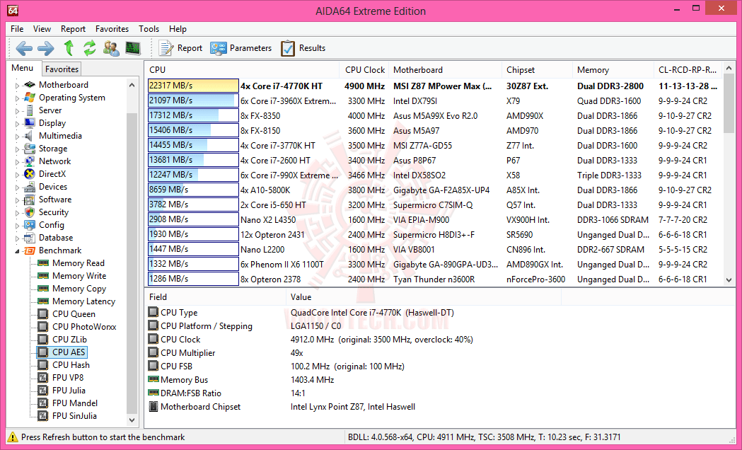
2.RAM speed
4800MHz
It can support faster memory, which will give quicker system performance.
3.overclocked RAM speed
6400MHz
The motherboard supports overclocking the RAM to a higher speed. By increasing the speed at which the memory runs, you can boost the performance of your computer.
4.memory slots
More memory slots (also known as DIMM slots) allow you to add more RAM to your computer. It is also useful when upgrading, as you can add RAM to an empty slot instead of replacing an existing memory module.
5.DDR memory version
DDR (Double Data Rate) memory is the most common type of RAM. Newer versions of DDR memory support higher maximum speeds and are more energy-efficient.
6.memory channels
More memory channels increases the speed of data transfer between the memory and the CPU.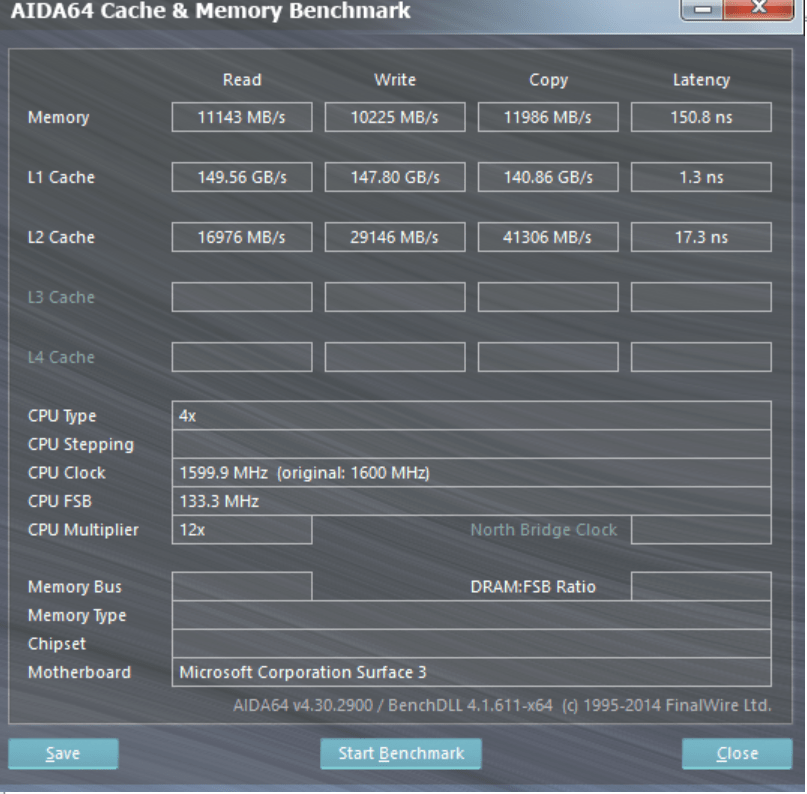
7.Supports ECC memory
✔Gigabyte Z690 Aorus Master
Error-correcting code memory can detect and correct data corruption. It is used when is it essential to avoid corruption, such as scientific computing or when running a server.
Ports
1.USB 3.2 Gen 2 ports (USB-A)
USB 3.2 Gen 2 supports speeds of up to 10Gbps. It was formerly known as USB 3.1 Gen 2. These ports use the older USB-A connector.
2.USB 3.2 Gen 1 ports (USB-A)
USB 3.2 Gen 1 supports speeds of up to 5Gbps. It was formerly known as USB 3.1 Gen 1 and USB 3.0. These ports use the older USB-A connector.
3.USB 3.2 Gen 2 ports (USB-C)
USB 3.2 Gen 2 supports speeds of up to 10Gbps. It was formerly known as USB 3.1 Gen 2. These ports use the USB-C connector.
4.USB 3.2 Gen 1 ports (USB-C)
Unknown. Help us by suggesting a value.
USB 3.2 Gen 1 supports speeds of up to 5Gbps. It was formerly known as USB 3.1 Gen 1 and USB 3.0. These ports use the USB-C connector.
5.USB 2.0 ports
More USB 2.0 ports allow you to connect more devices to your computer that support USB 2.0.
6.USB 3.2 Gen 2×2 ports
USB 3.2 Gen 2×2 was introduced in 2019. It supports speeds of up to 20Gbps and uses the USB-C connector.
7.USB 4 40Gbps ports
Unknown. Help us by suggesting a value.
This version of USB 4 supports very high speeds of up to 40Gbps. Unlike USB 3.2, USB 4 can dynamically allocate bandwidth to video and data. These ports use the USB-C connector.
8.USB 4 20Gbps ports
Unknown. Help us by suggesting a value.
This version of USB 4 supports speeds of up to 20Gbps. Unlike USB 3.2, USB 4 can dynamically allocate bandwidth to video and data. These ports use the USB-C connector.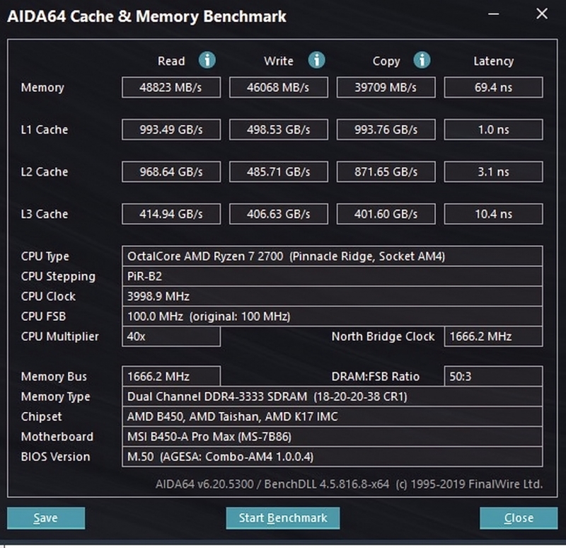
9.Thunderbolt 4 ports
Unknown. Help us by suggesting a value.
The number of USB ports that are compatible with Thunderbolt 4. These ports support speeds of up to 40Gbps, including a minimum of PCIe 32Gbps. This guarantees that it can support two external 4K displays (or one external 8K display).
Connectors
1.USB 3.2 Gen 1 ports (through expansion)
Unknown. Help us by suggesting a value.
The number of USB 3.2 Gen 1 ports that can be added by using the USB headers (connectors) on the motherboard.
2.USB 3.2 Gen 2 ports (through expansion)
Unknown. Help us by suggesting a value.
The number of USB 3.2 Gen 2 ports that can be added by using the USB headers (connectors) on the motherboard.
3.USB 2.0 ports (through expansion)
The number of USB 2.0 ports that can be added by using the USB headers (connectors) on the motherboard.
4.SATA 3 connectors
SATA is an interface used to connect mass storage devices such as hard drives and Blu-ray drives. SATA 3 has a native transfer rate of 6 Gbit/s, which is twice as fast as SATA 2, the previous revision. This is particularly useful if you use an SSD as it can perform at higher speeds.
5.fan headers
Fan headers are connection points on the motherboard that cooling fans can be connected to. Fans can also be connected straight to the power supply, but when connected to the motherboard you gain much finer control over them through software.
6.USB 3.0 ports (through expansion)
The motherboard has USB 3.0 headers, which are pin connections that you can connect additional USB ports to.
7.M.2 sockets
M.2 is an interface used to connect different types of devices, mainly mass storage devices like M.2 SSDs. It is a revision of mSATA and can support much higher data transfer rates.
8.Has TPM connector
✔Gigabyte Z690 Aorus Master
Trusted Platform Module (TPM) is a component that significantly increases security. One example is that it allows encryption keys to be created in a secure environment, minimizing the risk of a hacker gaining access.
9.U.2 sockets
U.2 is an interface used to connect different types of devices, mainly mass storage devices. It has the same performance as M.2, but U.2 SSDs come in the form of regular 2.5″ SATA drives and could therefore support much higher capacities than mSATA drives.
Expansion slots
1.PCIe 3.0 x16 slots
Unknown. Help us by suggesting a value.
PCIe slots allow you to connect various components to the motherboard, such as graphics cards and sound cards. The number after the ‘x’ represents the number of lanes, with more lanes supporting higher data transfer rates. PCI Express 3.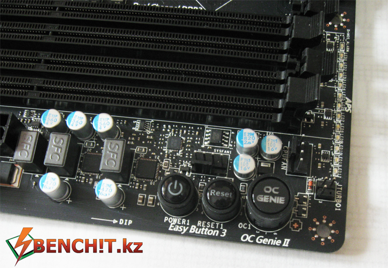 0 has a bit rate of 8 GT/s, delivering 985 MB/s per lane.
2.PCIe 4.0 x16 slots
Unknown. Help us by suggesting a value.
PCIe slots allow you to connect various components to the motherboard, such as graphics cards and SSDs. The number of data-transmission lanes (specified by the number after the ‘x’) determines the data transfer rate. PCIe 4.0 provides a 16 GT/s bit rate that doubles the bandwidth provided by PCIe 3.0.
3.PCIe x1 slots
Using PCIe slots, you can connect different components to your motherboard, such as graphics cards and RAID cards. The number after the ‘x’ represents the number of data-transmission lanes. More lanes result in faster data transfer rates. A PCIe x1 slot has one lane and can move data at one bit per cycle.
4.PCI slots
PCI slots allow you to connect peripherals to the motherboard, most commonly graphics cards but also others such as sound cards and network cards. PCI has been superseded by PCI Express which offers faster data transfer rates, but many cards today still use PCI.
5.PCIe 2.0 x16 slots
PCIe slots allow you to connect graphics cards, SSDs, and other components to the motherboard. The number after the ‘x’ represents the number of lanes, with more lanes supporting higher data transfer rates. PCI Express 2.0 has a transfer rate of 5 GT/s, providing 500 MB/s per lane.
6.PCIe x4 slots
PCIe slots enable you to connect various components to your motherboard, for example, graphics cards, RAID cards, SSDs. The number of data-transmission lanes (specified by the number following ‘x’) determines the data transfer rate. A PCIe x4 slot has 4 lanes, with a speed of 4 bits per cycle.
7.PCIe x8 slots
PCIe slots allow you to connect components such as graphics cards and sound cards to the motherboard. The number after the ‘x’ represents the number of data-transmission lanes. More lanes result in faster data transfer rates. A PCIe x8 slot has 8 lanes and can move data at 8 bit per cycle.
Audio
1.Signal-to-Noise ratio (DAC)
When a digital signal is converted to an analog one (for example when playing audio through speakers or headphones), a certain amount of noise is carried in the signal. A higher SNR means that there is less noise and the audio quality is better.
2.audio channels
Each channel is a separate stream of audio information. More channels can provide a more realistic experience, such as providing surround sound.
3.Has S/PDIF Out port
✔Gigabyte Z690 Aorus Master
S/PDIF is an interface used to transmit digital audio with high fidelity.
4.audio connectors
More connectors means that more audio devices such as speakers or microphones can be connected.
Storage
1. Supports RAID 1
✔Gigabyte Z690 Aorus Master
RAID is a storage technology that combines multiple disks into one unit. RAID 1 mirrors the data across the drives. This gives you greater data security as if one drive fails, the data will still be accessible from another.
2.Supports RAID 10 (1+0)
✔Gigabyte Z690 Aorus Master
RAID is a storage technology that combines multiple disks into one unit. RAID 10 (1+0) stripes and mirrors the data across the drives. It gives increased capacity and performance compared to a single disk. It also provides greater data security as if one drive fails, the data will still be accessible from another.
3.Supports RAID 5
✔Gigabyte Z690 Aorus Master
RAID is a storage technology that combines multiple disks into one unit. RAID 5 stripes the data across the drives, giving increased performance compared to a single disk. It also provides greater data security as if one drive fails, the data will still be accessible from another due to the use of parity.
4.Supports RAID 0
✔Gigabyte Z690 Aorus Master
RAID is a storage technology that combines multiple disks into one unit. RAID 0 stripes the data across the drives, giving increased performance and capacity compared to a single drive. The drawback is that if one drive fails, you lose the data on all drives.
5.Supports RAID 0+1
✖Gigabyte Z690 Aorus Master
RAID is a storage technology that combines multiple disks into one unit. RAID 0+1 stripes and mirrors the data across the drives. This gives increased capacity and performance compared to a single disk. It also provides greater data security in case one drive fails, as the data will still be accessible from another.
Price comparison
Cancel
Which are the best motherboards?
Motherboards with Wi-Fi 6
Motherboards (1 — 5)
| MSI WS WRX80 | Gigabyte Z690 Aorus Master | Asus ROG Maximus Z790 Extreme | MSI MEG Z790 Ace | Asus ROG Maximus Z790 Hero | Gigabyte Z690 Aero D | Asus ROG Crosshair X670E Extreme | Asus ROG Maximus Z690 Hero | Asus ROG Maximus Z690 Extreme | Gigabyte Z490 Aorus Xtreme | Gigabyte Aorus X670E Xtreme | Asus ROG Strix X570-E Gaming | Gigabyte Z590 Aorus Xtreme | Asus ROG Maximus Z690 Formula | Asus ROG Maximus Z690 Hero EVA Edition | |
| Image | |||||||||||||||
| Best price | |||||||||||||||
| Best price | |||||||||||||||
Wi-Fi 6 (802. 11ax) connectivityWi-Fi 6, released in 2019, is based on the IEEE 802.11ax wireless LAN standard. Designed to operate in all frequency bands between 1 and 6 GHz, it offers higher data rates and lower latency compared to previous Wi-Fi technologies. 11ax) connectivityWi-Fi 6, released in 2019, is based on the IEEE 802.11ax wireless LAN standard. Designed to operate in all frequency bands between 1 and 6 GHz, it offers higher data rates and lower latency compared to previous Wi-Fi technologies. |
|||||||||||||||
| Wi-Fi 6 (802.11ax) connectivityWi-Fi 6, released in 2019, is based on the IEEE 802.11ax wireless LAN standard. Designed to operate in all frequency bands between 1 and 6 GHz, it offers higher data rates and lower latency compared to previous Wi-Fi technologies. | ✔ | ✔ | ✔ | ✔ | ✔ | ✔ | ✔ | ✔ | ✔ | ✔ | ✔ | ✔ | ✔ | ✔ | ✔ |
| RAM speedIt can support faster memory, which will give quicker system performance. | |||||||||||||||
| RAM speedIt can support faster memory, which will give quicker system performance. | 3200MHz | 4800MHz | 5600MHz | 5600MHz | 5600MHz | 4800MHz | 5600MHz | 4800MHz | 4800MHz | 2933MHz | 5200MHz | 2666MHz | 3200MHz | 4800MHz | 4800MHz |
Overclocked RAM speedThe motherboard supports overclocking the RAM to a higher speed.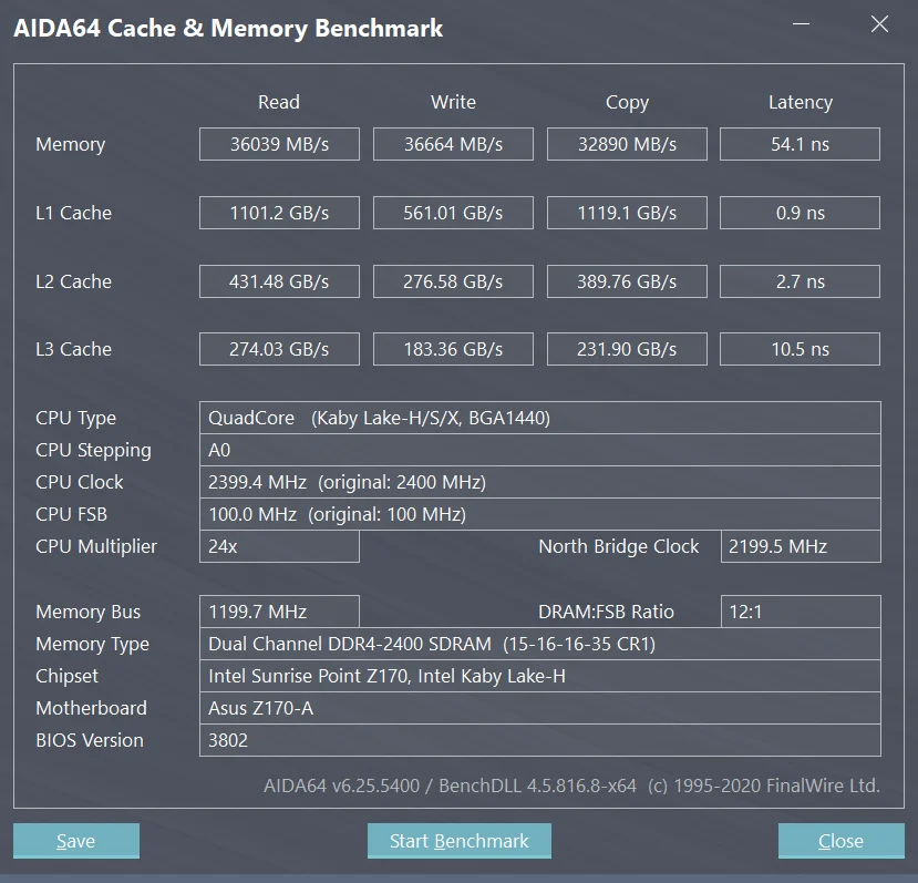 By increasing the speed at which the memory runs, you can boost the performance of your computer. By increasing the speed at which the memory runs, you can boost the performance of your computer. |
|||||||||||||||
| Overclocked RAM speedThe motherboard supports overclocking the RAM to a higher speed. By increasing the speed at which the memory runs, you can boost the performance of your computer. | 4400MHz | 6400MHz | 7200MHz | 7600MHz | 7200MHz | 6400MHz | 6400MHz | 6400MHz | 6400MHz | 5000MHz | 6600MHz | 4400MHz | 5400MHz | 6400MHz | 6400MHz |
| Memory slotsMore memory slots (also known as DIMM slots) allow you to add more RAM to your computer. It is also useful when upgrading, as you can add RAM to an empty slot instead of replacing an existing memory module. | |||||||||||||||
Memory slotsMore memory slots (also known as DIMM slots) allow you to add more RAM to your computer. It is also useful when upgrading, as you can add RAM to an empty slot instead of replacing an existing memory module. |
8 | 4 | 4 | 4 | 4 | 4 | 4 | 4 | 4 | 4 | 4 | 4 | 4 | 4 | 4 |
| Maximum memory amountThe maximum amount of memory (RAM) supported. | |||||||||||||||
| Maximum memory amountThe maximum amount of memory (RAM) supported. | 2000GB | 128GB | 128GB | 128GB | 128GB | 128GB | 128GB | 128GB | 128GB | 128GB | 128GB | 128GB | 128GB | 128GB | 128GB |
| Fan headersFan headers are connection points on the motherboard that cooling fans can be connected to. Fans can also be connected straight to the power supply, but when connected to the motherboard you gain much finer control over them through software. | |||||||||||||||
Fan headersFan headers are connection points on the motherboard that cooling fans can be connected to. Fans can also be connected straight to the power supply, but when connected to the motherboard you gain much finer control over them through software. |
6 | 10 | 6 | 8 | 6 | 8 | 6 | 6 | 6 | 8 | 10 | 6 | 10 | 6 | 6 |
| SATA 3 connectorsSATA is an interface used to connect mass storage devices such as hard drives and Blu-ray drives. SATA 3 has a native transfer rate of 6 Gbit/s, which is twice as fast as SATA 2, the previous revision. This is particularly useful if you use an SSD as it can perform at higher speeds. | |||||||||||||||
| SATA 3 connectorsSATA is an interface used to connect mass storage devices such as hard drives and Blu-ray drives. SATA 3 has a native transfer rate of 6 Gbit/s, which is twice as fast as SATA 2, the previous revision. This is particularly useful if you use an SSD as it can perform at higher speeds. | 8 | 6 | 6 | 6 | 6 | 6 | 6 | 6 | 6 | 6 | 6 | 8 | 6 | 6 | 6 |
PCIe 3.0 x16 slotsPCIe slots allow you to connect various components to the motherboard, such as graphics cards and sound cards. The number after the ‘x’ represents the number of lanes, with more lanes supporting higher data transfer rates. PCI Express 3.0 has a bit rate of 8 GT/s, delivering 985 MB/s per lane. The number after the ‘x’ represents the number of lanes, with more lanes supporting higher data transfer rates. PCI Express 3.0 has a bit rate of 8 GT/s, delivering 985 MB/s per lane. |
|||||||||||||||
| PCIe 3.0 x16 slotsPCIe slots allow you to connect various components to the motherboard, such as graphics cards and sound cards. The number after the ‘x’ represents the number of lanes, with more lanes supporting higher data transfer rates. PCI Express 3.0 has a bit rate of 8 GT/s, delivering 985 MB/s per lane. | N.A. | N.A. | 0 | 0 | 0 | N.A. | 0 | 0 | 0 | 3 | 1 | N.A. | N.A. | 0 | 0 |
| USB 3.0 portsMore USB 3.0 ports allow you to connect more devices to your computer that support USB 3.0. USB 3.0 is an improved version of USB 2.0 which offers faster transfer rates. | |||||||||||||||
USB 3.0 portsMore USB 3.0 ports allow you to connect more devices to your computer that support USB 3. 0. USB 3.0 is an improved version of USB 2.0 which offers faster transfer rates. 0. USB 3.0 is an improved version of USB 2.0 which offers faster transfer rates. |
N.A. | N.A. | N.A. | N.A. | N.A. | N.A. | N.A. | N.A. | N.A. | N.A. | N.A. | N.A. | N.A. | N.A. | N.A. |
| USB 2.0 portsMore USB 2.0 ports allow you to connect more devices to your computer that support USB 2.0. | |||||||||||||||
| USB 2.0 portsMore USB 2.0 ports allow you to connect more devices to your computer that support USB 2.0. | 0 | 0 | 0 | 0 | 0 | 0 | 0 | 2 | 0 | 2 | 4 | 0 | 0 | 3 | 2 |
Did you know that Samsung was the first major manufacturer to release Wi-Fi 6 compatible smartphones when they released the Galaxy Fold and Galaxy S10? That was just in 2019. But, what about motherboards with Wi-Fi 6 capabilities? They’re out there, but they’re just not as widespread yet.
Simply put, the technology is pretty new, and despite offering users the possibility of up to a 75% decrease in latency and increased connection steadiness, the adoption and incorporation of Wi-Fi 6 in new devices such as motherboards are still slowly happening. Here’s what to know.
What is Wi-Fi 6?
Wi-Fi 5 is technically called 802.11ac, and Wi-Fi 6 is based on the IEEE 802.11ax standard and offers higher top speeds than its predecessor. How does it kick up the speed compared to Wi-Fi 5? It uses an increased focus on connectivity to ensure optimal performance and low latency in wireless spaces such as corporate networks and even public venues. This increased connectivity, particularly in public spaces, can lead to enhanced possibilities for innovations in technology, augmented reality, healthcare, and even in the corporate sphere.
Which motherboards have Wi-Fi 6?
It’s worth mentioning again that perhaps the biggest benefit of Wi-Fi 6 for computer users and network owners is that it allows for the connection of unlimited devices. This means that a large corporate building with ten floors all full of offices and computers can easily connect to the same network without having to whip up some wild network scheme.
With that in mind, however, few motherboards currently support Wi-Fi 6; the ones that do tend to be motherboards designed for graphics-heavy gaming and streaming. The Asus ROG Maximus XII Hero is one such example, as is the ASUS TUF Gaming Z490-Plus. The former uses a Wi-Fi 6 AX201 module to allow for Wi-Fi 6 connectivity, allowing users to experience speeds up to 40% faster than previous versions of Wi-Fi.
What else to look for in a motherboard
Right now, you’ll have to settle for a high-end, gaming-geared motherboard if you want to reap the benefits of Wi-Fi 6. And, if you’re opting for a motherboard of that caliber, be sure to check out the other specs as well. Namely, the number of ports and the types of connections available are essential features to look at. Check to see how many SATA 3 connections there are and whether or not there is an HDMI connection straight to the motherboard. Read more on that here where we talk about the motherboards with the best connectivity.
How to check the motherboard for serviceability
Test mode . From the drop-down list, you can select Small, Medium, or Large dataset. According to unverified but reliable sources, when selecting Small data, only the processor is tested for errors. Selecting Medium data tests the CPU and RAM. When you select Large Data, the processor, memory, and motherboard chipset are tested.
Number of threads is the number of threads. We set a tick — Auto in order to use all possible. The tested Intel core i3 2125 processor is dual-core, but thanks to Hyper-threading technology, each physical core can pull two threads at once. That is, it turns out 4 logical cores.
Before starting the test, it is advisable to close all running programs and exit programs that hang in the notification area.
In the folder with the current date there will be graphs of various parameters from the processor load. Everything is clearly shown there.
If errors are found during the test, you will see a warning. What to do in this case, read the Conclusion.
The first and necessary step in the diagnosis is a visual inspection of the condition of the motherboard. We have to identify the presence of visible damage on its surface. To do this, remove the cover of the system unit and look directly at the motherboard. The first thing to look for is whether the electrolytic capacitors are swollen (as shown in the figure).
If so, then you will have to change the entire board (replacing individual capacitors will not do). If swelling is not found, proceed to further inspection.
Carefully inspect other electrical components for surface discoloration and faded writing (shown).
Methods for dialing board parts with a multimeter
Often a situation arises when a household appliance stops working due to a failed small minor part. Therefore, many novice radio amateurs would like to know the answer to the question of how to ring the board with a multimeter. The main thing in this case is to quickly find the cause of the breakdown.
Before performing an instrumental check, it is necessary to inspect the board for damage.![]() The electrical circuit of the board must be without damage to the bridges, the parts must not be swollen and black. Here are the rules for checking some elements, including the motherboard.
The electrical circuit of the board must be without damage to the bridges, the parts must not be swollen and black. Here are the rules for checking some elements, including the motherboard.
Inspection of individual parts
Let’s take a look at a few parts that break down the circuit, and with it all the equipment.
Resistor
On various boards, this part is used quite often. And just as often, when they break down, the device fails. Resistors are easy to check for performance with a multimeter.
This requires a resistance measurement. With a value tending to infinity, the part should be replaced. Part failure can be determined visually. As a rule, they turn black due to overheating.
If the value changes more than 5%, the resistor needs to be replaced.
Diode
It doesn’t take long to test a diode for a fault. Turn on the multimeter to measure the resistance.
Red probe for the part anode, black probe for the cathode — the reading on the scale should be from 10 to 100 ohms.
We rearrange the multimeter probes, now the minus (black probe) on the anode is a reading tending to infinity. These values indicate the health of the diode.
Inductor
The board rarely fails due to this part. As a rule, a breakdown occurs for two reasons:
- turn short circuit;
- open circuit.
After checking the resistance value of the coil with a multimeter, if the value is less than infinity, the circuit is not broken. Most often, the resistance of the inductance has a value of several tens of ohms.
Turn-to-turn fault is a little more difficult to detect. To do this, we transfer the device to the sector for measuring the voltage of the circuit. It is necessary to determine the magnitude of the self-induction voltage. We apply a small voltage current to the winding (the crown is most often used), we close it with a light bulb. The light blinked — there is no circuit.
Loop
In this case, you should ring the input contacts on the board and on the loop itself. We start the multimeter probe into one of the contacts and start ringing.
If there is a beep, then these contacts are good. In the event of a malfunction, one of the holes will not find a “pair” for itself.
If one of the contacts rings with several at once, it means that it’s time to change the loop, since there is a short circuit on the old one.
IC
A wide variety of these parts are available. It is quite difficult to measure and determine the malfunction of a microcircuit with a multimeter; pci testers are most often used.
The multimeter does not allow measurement, because in one small part there are several dozens of transistors and other radio elements.
And in some of the latest developments, billions of components are concentrated.
The problem can only be determined by visual inspection (case damage, discoloration, broken leads, high heat).
If a part is damaged, it must be replaced.
Often when a microcircuit breaks down, the computer and other devices stop working, so the search for a breakdown should begin with an examination of the microcircuit.
The motherboard tester is the best option for determining the breakdown of a single part and assembly. By connecting the POST card to the motherboard and starting the test mode, we get information about the failure node on the device screen. Even a beginner who does not have special skills can perform an examination with a pci tester.
Fourth step
Let’s do a more detailed test by disconnecting all the components connected to the motherboard and try to find out if there is a problem in any of them. To do this, disconnect all connectors (RAM, video card), except for the central processor and power. After that, turn on the power supply and speaker to the network and press the power button on the computer.
Wait a minute, you might be interested to know where the clipboard is located in the phone or why the BIOS does not see the hard drive.
If the motherboard is OK, you should hear one short and one long speaker beep, which indicates a malfunction of the RAM and indirectly indicates that everything is in order with the board. If the speaker is silent, then the motherboard is faulty. In this case, it will have to be replaced.
Next, connect the RAM modules and listen to the speaker again. If the RAM is good, you will hear one long beep and two short beeps. This indicates that a malfunction is possible in the video card.
We repeat the procedure, only this time, connecting the video card and monitor. If all is well, then you will hear one beep in the speaker and see the BIOS splash screen on the monitor. If not, the problem is with the video card. However, the signal may be absent, and the video card will also be working. This can happen if the central processor has an integrated graphics core (you can determine its presence in the instruction manual or on the manufacturer’s website).
How to fix motherboard problems — Computer help at home.
If we draw an analogy and compare a computer with a building, then the motherboard will undoubtedly be its foundation. A good foundation always guarantees stable performance. Thanks to modern technology, the computer is getting smaller, and works faster and quieter. At the same time, the computer becomes more and more complex. Therefore, diagnosing computer hardware these days is not an easy task. If you are unsure of your knowledge and skills, it is better to seek help from a computer service.
Motherboard repair can be roughly divided into two categories. The first is the replacement and soldering of damaged parts (capacitors) of the motherboard and hope for the best in the future. Most often, this repair method is used for laptops. The second is the replacement of either the motherboard itself, or the replacement of faulty components connected to the motherboard.
It is difficult to get a burnt-out and then re-soldered part of the microcircuit to work properly as well as it worked before. That is why most of the procedures known as «Motherboard Repair» remain the work of enthusiasts, since the best solution for the vast majority of users will be to replace a faulty computer component.![]() So, let’s proceed directly to the description of troubleshooting the motherboard and the components connected to it.
So, let’s proceed directly to the description of troubleshooting the motherboard and the components connected to it.
Troubleshooting motherboards.
Hardware diagnostics can be a real headache even for an experienced user. There are too many reasons to look for and analyze. Most motherboard repairs, as mentioned above, remain the prerogative of professionals or amateur enthusiasts. Troubleshooting can be very time consuming. However, there are a few fairly common problems.
Replacing capacitors. The constant problem with capacitors is well known to professionals and amateur enthusiasts. Capacitors are the first thing to check. The problem is eliminated by replacing the burned-out capacitor with a new one. Visually, a burned-out capacitor has a “swollen” upper surface and smudges of electrolytic liquid. Most burnt capacitors will “leak”, the electrolyte inside will be visible as a dried crust on the outside of the capacitor, or on the motherboard itself. In the worst case scenario, the capacitor explodes due to too much electrical voltage.
To replace the capacitors, you will need:
- Special program-controlled soldering iron and soldering tool.
- Original capacitor of the same capacity as the replacement.
- Soldering experience and risk awareness. Because one wrong move, and you will damage the internal circuits and ruin the board completely. You must unsolder the capacitor leads from the board, remove the failed capacitor, and then solder the leads of the new capacitor. You must be very careful not to reverse the polarity of the capacitor.
Diagnose motherboard components. Look for BIOS POST beeps. To diagnose a problem, you need to know where to look for it. The first thing you need to pay attention to is POST BIOS (Power-On Self-Test). If your computer emits a series of beeps when the system boots up, then there are certain problems with one or another component. The sound signal directly signals in which component of the system unit problems are detected. Pay special attention to the type of sound signal (duration — short or long and the number of sound signals).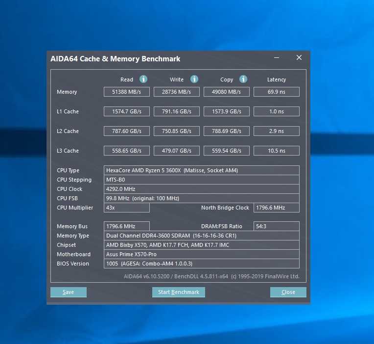 At this link, you can read the reference table of sound signals in order to find out the cause of the problem.
Diagnostic and repair manual for computers
If your computer constantly “flies” into a reboot or does not boot at all, then you need to know how malfunctions with one or another system component manifest themselves. Next, we will look at how to diagnose and solve a particular problem.
Faulty power supply. Diagnosis: Faulty power supply, the most common cause of computer failure. Finding a bad power supply is pretty easy. If your computer does not turn on when you press the power button, then the fault most likely lies with this component. In any case, first check the connection of the cord to the outlet, if a UPS is connected, then to check, connect the system unit to the power supply directly, check all the cords. If all the cords and cables are in order, then almost certainly the problem is in the power supply.
Solution: PSU is quite easy to replace, just unscrew it from the case and disconnect all connectors. When buying a new one, remember that it must be at least as powerful as the one being replaced.
Video adapter Diagnosis: video adapter (video card), works with computer graphics and is responsible for the image on the monitor screen. This is the next part to check after the PSU. If the computer is turned on, then press the Num Lock key on the keyboard, the corresponding indicator on the keyboard panel should turn on. If the indicator is working but you can’t see anything on the monitor (which is on), then your video card is most likely burned out.
Solution: This problem is caused by overheating of the graphics card, most commonly due to dust. The cause may be a non-working cooling fan. Another possible cause could be a discharge of static electricity. It is necessary to remove the cover of the system unit, check the operation of the fan (if installed), clean the card and heatsink from dust. If, after cleaning, the system still crashes, then you should replace the faulty video card. It is also possible to “solder” a faulty video card, but we do not advise you to do this, this is only a temporary measure and once a burnt card does not live long.
RAM Diagnosis: Common symptoms of a failed RAM module include BSoD (Blue Screen of Death), slow system speed, and slow booting of the computer. The first thing to do is to check if the RAM modules are properly inserted into the slots. If the RAM modules are inserted into the slots correctly, then the RAM will probably need to be replaced.
Solution: RAMs are highly susceptible to damage due to power surges and static discharges. Their replacement is relatively simple and cheap.
Now consider secondary solutions and additional precautions.
Flashing the BIOS Another way to solve problems with the motherboard is to flash the BIOS of the motherboard, or, as they say, its firmware. But there are a few critical things about this case that you need to be aware of. First, you must clearly know that the problem is in the software, and not in the hardware of the motherboard. To do this, you must first test each component of the system. Secondly, the process itself is very risky. The BIOS is a critical element in the motherboard. To flash the BIOS, you need an «image» of the firmware. The process comes down to updating the BIOS to the latest version, or installing the same one.
First you need to find out the model number of the motherboard and the current BIOS version, then you need to go to the manufacturer’s website and find the appropriate update. Save the downloaded software to a CD or flash drive. Insert CD/USB drive and restart your computer. The disk executable file will start, then just follow the commands on the screen. This process takes about 10 seconds. If a power failure occurs at this point, then you risk getting an incorrectly written BIOS and a non-working motherboard. The process itself is quite simple, but we strongly advise you not to do this unless you know that this is the only solution, because the risks are too high.
Static Discharge The board can be easily damaged by static electricity, which causes a small voltage spike, enough to kill it. Therefore, you must take two precautions: The first of these is to ensure that the outlet to which you plug your computer is properly grounded.
The second concerns human contact with the board. Every time you «tinker» with the system unit, touch the metal on the case or the board itself, you run the risk of «running into» a discharge of static electricity. This current is generated when you run your socks or a comb across a carpet or sofa. When working with various computer components, you should place them on an antistatic mat (rubber mat).
We looked at the main causes of failure of the motherboard and the computer as a whole. To correctly diagnose and repair a computer yourself, you must have more skills than the average user. Therefore, you need to consider that when you try to repair a computer yourself, you act at your own peril and risk, and your wrong actions can disable even more components and increase the cost of computer repairs.
wefavor.ru
How to check the motherboard for performance — video
So, we have analyzed all the necessary steps for self-diagnosis of your motherboard and how to check the motherboard for performance. If it was not possible to identify the presence of problems, you have only one step left — contact the service center. However, I hope that my article will still be useful and accessible, and the recommendations outlined will help you do without contacting specialists. Wish you luck!
Previous post Where is the clipboard in the phone and what is it?
Next post What is the best and fastest browser?
Table of sounds that indicate a problem with the motherboard:
There are 3 types of BIOS in total, each of which is endowed with its own logic.
You can find out which one you have by marking the motherboard.
The sounds for each are as follows:
Table of BIOS sounds — speaker, announcing the problem of AMI motherboard failure:
Table of BIOS speaker sounds that notify of a problem with the motherboard Award:
Table of sounds of the BIOS speaker that notifies of a problem with the Phoenix motherboard:
The procedure for further actions:
So, there is sound.
Turn off the motherboard, and first of all insert one ram (RAM) chip.
Restart and listen.
If successful, we will be warned about a video card malfunction (see the table with sounds and their sequence).
We connect the video adapter and, if required, additional power. Additionally, we connect a monitor to output a visual signal.
Turn on the computer and wait for the speaker’s signal.
If it is single and short, then your machine is fine. The cause was dust, metal shavings or a bent contact that was returned to its original shape. This is in case everything is in order with the capacitors.
But if the sound of a video card malfunction has not disappeared, then it is to blame.
Otherwise, you should look for sound adapters, hard drives and other connected peripherals.
How to test hard drive performance
Troubleshooting other items and LED indicator
Disconnect any static electricity before starting testing. Circuits on the motherboard are sensitive to any form of electrical charge, including static electricity from the human body.
Before proceeding with testing the functionality of the motherboard, it is necessary to exclude the malfunction of the power supply and of the processor . You need to make sure that the processor is stable, and it is recommended to connect a new power supply for the duration of the test. After connecting the motherboard to the power supply and starting it up, a colored LED indicator should light up, which notifies you of its working status. If this does not happen, you should understand the reasons that violate its work.
Dead Battery and Reset CMOS
A common cause of motherboard problems is a dead lithium battery. should check its voltage , it should be at least 2.9 V. The battery needs to be changed about once every 2-3 years, and if the reason is in it, then to solve the problem, it is enough to replace the dead battery with a new one.
Another way to check the device is resetting the CMOS . To reset the factory settings, it is necessary to close the corresponding contacts for 20 seconds. To do this, you need to rearrange the jumper, and then return it to its original position. The jumper is located on the system board near the batteries and is labeled CLR_CMOS or CCMOS . Such actions can lead to the restoration of the motherboard.
BONUS! Information about the motherboard in the HTML report
This application is called LookInMyPC and you can download it from the developers website (in English, there is a portable version that does not require installation)
https://www.lookinmypc.com/download.htm
you can choose what exactly to generate a report about, but we leave everything as it is and click the “Generate Report” button … all that remains is to wait until the report is generated — this is fast.
The report file will open in any browser, in the «BIOS Information» block in the «Board Product ID» line and there will be the name of our motherboard.
In fact, the report contains a lot of interesting and useful information, and as for the English language, Google Chrome translates everything wonderfully.
The report generates a lot of data about the software part, and you can view it at any time without the program itself — this is very convenient
Checking and troubleshooting the motherboard
Diagnostics of the motherboard is carried out using special equipment, which is rarely available to an ordinary user. Even for an experienced specialist, such a check can be a very difficult task: there are many causes of breakdowns that need to be analyzed, and the analysis does not always give the right results.
Repair work on the motherboard, as well as correct diagnosis, is best left to professionals.
But if you’re an enthusiast, here are some of the most common motherboard problems you’ll encounter.
Most likely, after all, you still have to contact the service center.

Visually burned capacitor can be identified by the «swollen» surface and smudges of electrolyte. In the worst of the options, a burned-out capacitor can even explode if it burns out.
How to check the motherboard for serviceability
Author Aleksey Reading 5 min Views 21.3k. Published by Updated by
Table of Contents
- Motherboard Health Check — Beginning
- Motherboard Power and CMOS Memory Test
- Step by Step Motherboard Performance Test
”, errors indicating some problems, there were problems loading the system, up to the complete absence of its signs of life, then the reason for this may be a malfunction of the motherboard. In this situation, you can take the computer to a service center, where computer diagnostics will cost you money, or try to test the motherboard yourself.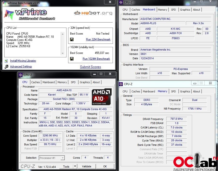 But how to check the performance of the motherboard at home if there is no specialized equipment, the necessary skills and knowledge? This is what we will talk about next.
Checking the functionality of the motherboard — beginning
Diagnostics of the motherboard, like any other electronic device, begins with an external examination and only after it, provided that there are no visible signs of damage, proceed to the following tests.
To do this, remove the left cover of the computer system unit to access the motherboard. Next, we inspect it for obvious defects.
First, you need to pay attention to the condition of the electrolytic capacitors. They should not be swollen, otherwise, this may be the cause of a complete or partial malfunction of the system board.
Secondly, we inspect other electrical elements (resistors, microcircuits, etc.) for signs of burnout. As a rule, temperature effects, due to increased load, power surges or short circuits, lead to their failure, followed by a change in their color. They become darker, and the inscriptions on them, if any, become difficult to read.
If any of the listed signs or suspicions of their presence is identified, it is better to contact specialists.
Checking the power supply of the motherboard and CMOS memory
So, external inspection did not help determine the health of the motherboard. So, next we will check its power supply system and the CMOS memory built into it.
Turn on the power supply and look at the signal LED located on the MP. If it is on, it means that power is coming to it, and there are no complaints about the power supply. Unfortunately, such a power indication is not present on all MPs.
If there is no glow, and the power supply fan is stationary, then most likely the reason lies in the PSU itself or the PC power button. How to check these two computer components for operability, we explained in this article.
Next, after making sure that the correct voltage is coming from the power supply, we check the backup power for the CMOS memory provided by a CR2032 or CR2025 battery. What role does this memory play and how to reset it, we wrote in this article. We remove the battery and measure the voltage it produces with a multimeter. It should be in the region of 3 V. If it does not correspond to the norm and is greatly underestimated, then it should be replaced, because it can also cause problems.
Step-by-step test of the motherboard for performance
If the first two steps to identify the causes of the malfunction of the motherboard did not give results, then we will test it step by step, connecting all the components of the system unit to it in turn and focusing on the sound signals emitted by the speaker.
In this case, before checking the functionality of the motherboard, or rather, determining the faulty node connected to it, disconnect all connectors of the internal devices of the system unit from it, leaving only the power cable on. In addition, we remove all RAM modules, a video card and other expansion cards from the slots, leaving only the central processor untouched.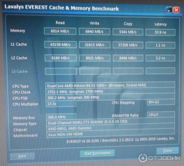
After, we turn on the computer and pay attention to the fact that in the absence of memory modules, a working motherboard should give out one short and one long beep, indicating a malfunction of the RAM. If the speaker is silent, then, most likely, the MP should be replaced.
Please note : all types and beeps described in this article that indicate a malfunction correspond to the BIOS AWARD. What BIOS exactly for your MP you need to look in the description of its characteristics.
Next, we add memory modules one by one to the corresponding slots and check the speaker’s reaction. Provided that the memory modules are all serviceable, it should give out one long and two short beeps, already talking about a possible malfunction associated with the video system. Therefore, the next step is to install the video card, connect the monitor to it and check the performance of the motherboard by the presence of one sound signal and the appearance of the BIOS splash screen on the monitor.