Intel Core i9-12900K review | 67 facts and highlights
80points
Intel Core i9-12900K
i9-12900KF
Intel Core i9-12900K
Why is Intel Core i9-12900K better than the average?
- CPU speed?
8 x 3.2GHz & 8 x 2.4GHzvs12.5GHz - RAM speed?
4800MHzvs2489.55MHz - CPU threads?
24vs7.73 - Semiconductor size?
10nmvs16.99nm - Turbo clock speed?
5.2GHzvs3.83GHz - L2 cache?
14MBvs2.23MB - PassMark result?
41317vs8680.27 - L3 cache?
30MBvs9.54MB
Which are the most popular comparisons?
Intel Core i9-12900K
vs
Apple M2
Intel Core i9-12900K
vs
AMD Ryzen 9 5950X
Intel Core i9-12900K
vs
Intel Core i7-12700K
Intel Core i9-12900K
vs
Intel Core i7-13700K
Intel Core i9-12900K
vs
Apple M1 Ultra
Intel Core i9-12900K
vs
Intel Core i5-13600K
Intel Core i9-12900K
vs
AMD Ryzen 7 5800X
Intel Core i9-12900K
vs
AMD Ryzen Threadripper Pro 5995WX
Intel Core i9-12900K
vs
Apple M1 Max
Intel Core i9-12900K
vs
Intel Core i9-12900KS
Price comparison
Cheap alternatives for Intel Core i9-12900K
User reviews
Overall Rating
Intel Core i9-12900K
6 User reviews
Intel Core i9-12900K
8. 7/10
6 User reviews
Features
Value for money
7.8/10
6 votes
Gaming
9.2/10
6 votes
Performance
9.0/10
6 votes
Reliability
8.5/10
6 votes
Energy efficiency
7.5/10
6 votes
Performance
CPU speed
8 x 3.2GHz & 8 x 2.4GHz
The CPU speed indicates how many processing cycles per second can be executed by a CPU, considering all of its cores (processing units). It is calculated by adding the clock rates of each core or, in the case of multi-core processors employing different microarchitectures, of each group of cores.
CPU threads
More threads result in faster performance and better multitasking.
turbo clock speed
5.2GHz
When the CPU is running below its limitations, it can boost to a higher clock speed in order to give increased performance.
Has an unlocked multiplier
✔Intel Core i9-12900K
Some processors come with an unlocked multiplier which makes them easy to overclock, allowing you to gain increased performance in games and other apps.
L2 cache
A larger L2 cache results in faster CPU and system-wide performance.
L3 cache
A larger L3 cache results in faster CPU and system-wide performance.
L1 cache
Unknown. Help us by suggesting a value.
A larger L1 cache results in faster CPU and system-wide performance.
L2 core
Unknown. Help us by suggesting a value.
More data can be stored in the L2 cache for access by each core of the CPU.
L3 core
Unknown. Help us by suggesting a value.
More data can be stored in the L3 cache for access by each core of the CPU.
Benchmarks
PassMark result
This benchmark measures the performance of the CPU using multiple threads.
PassMark result (single)
This benchmark measures the performance of the CPU using a single thread.
Geekbench 5 result (multi)
Geekbench 5 is a cross-platform benchmark that measures a processor’s multi-core performance. (Source: Primate Labs, 2022)
Cinebench R20 (multi) result
Cinebench R20 is a benchmark tool that measures a CPU’s multi-core performance by rendering a 3D scene.
Cinebench R20 (single) result
Cinebench R20 is a benchmark tool that measures a CPU’s single-core performance by rendering a 3D scene.
Geekbench 5 result (single)
Geekbench 5 is a cross-platform benchmark that measures a processor’s single-core performance. (Source: Primate Labs, 2022)
Blender (bmw27) result
Unknown. Help us by suggesting a value.
The Blender (bmw27) benchmark measures the performance of a processor by rendering a 3D scene. More powerful processors can render the scene in less time.
Blender (classroom) result
Unknown. Help us by suggesting a value.
The Blender (classroom) benchmark measures the performance of a processor by rendering a 3D scene. More powerful processors can render the scene in less time.
performance per watt
Unknown. Help us by suggesting a value.
This means the CPU is more efficient, giving a greater amount of performance for each watt of power used.
Integrated graphics
GPU clock speed
300MHz
The graphics processing unit (GPU) has a higher clock speed.
GPU turbo
1550MHz
When the GPU is running below its limitations, it can boost to a higher clock speed in order to give increased performance.
GPU execution units
A graphics processing unit (GPU) with a greater number of execution units can deliver better graphics.
supported displays
Using multiple displays you can create a larger workspace, making it easier to work across multiple apps.
DirectX version
DirectX is used in games, with newer versions supporting better graphics.
OpenGL version
OpenGL is used in games, with newer versions supporting better graphics.
OpenCL version
Some apps use OpenCL to apply the power of the graphics processing unit (GPU) for non-graphical computing. Newer versions introduce more functionality and better performance.
texture mapping units (TMUs)
Unknown. Help us by suggesting a value.
TMUs take textures and map them to the geometry of a 3D scene. More TMUs will typically mean that texture information is processed faster.
render output units (ROPs)
Unknown. Help us by suggesting a value.
The ROPs are responsible for some of the final steps of the rendering process, writing the final pixel data to memory and carrying out other tasks such as anti-aliasing to improve the look of graphics.
Memory
RAM speed
4800MHz
It can support faster memory, which will give quicker system performance.
maximum memory bandwidth
76.8GB/s
This is the maximum rate that data can be read from or stored into memory.
DDR memory version
DDR (Double Data Rate) memory is the most common type of RAM. Newer versions of DDR memory support higher maximum speeds and are more energy-efficient.
memory channels
More memory channels increases the speed of data transfer between the memory and the CPU.
maximum memory amount
The maximum amount of memory (RAM) supported.
bus transfer rate
Unknown. Help us by suggesting a value.
The bus is responsible for transferring data between different components of a computer or device.
Supports ECC memory
✖Intel Core i9-12900K
Error-correcting code memory can detect and correct data corruption. It is used when is it essential to avoid corruption, such as scientific computing or when running a server.
eMMC version
Unknown. Help us by suggesting a value.
A higher version of eMMC allows faster memory interfaces, having a positive effect on the performance of a device. For example, when transferring files from your computer to the internal storage over USB.
bus speed
Unknown. Help us by suggesting a value.
The bus is responsible for transferring data between different components of a computer or device.
Features
uses multithreading
✔Intel Core i9-12900K
Multithreading technology (such as Intel’s Hyperthreading or AMD’s Simultaneous Multithreading) provides increased performance by splitting each of the processor’s physical cores into virtual cores, also known as threads. This way, each core can run two instruction streams at once.
Has AES
✔Intel Core i9-12900K
AES is used to speed up encryption and decryption.
Has AVX
✔Intel Core i9-12900K
AVX is used to help speed up calculations in multimedia, scientific and financial apps, as well as improving Linux RAID software performance.
SSE version
SSE is used to speed up multimedia tasks such as editing an image or adjusting audio volume. Each new version contains new instructions and improvements.
Has F16C
✔Intel Core i9-12900K
F16C is used to speed up tasks such as adjusting the contrast of an image or adjusting volume.
bits executed at a time
Unknown. Help us by suggesting a value.
NEON provides acceleration for media processing, such as listening to MP3s.
Has MMX
✔Intel Core i9-12900K
MMX is used to speed up tasks such as adjusting the contrast of an image or adjusting volume.
Has TrustZone
✖Intel Core i9-12900K
A technology integrated into the processor to secure the device for use with features such as mobile payments and streaming video using digital rights management (DRM).
front-end width
Unknown. Help us by suggesting a value.
The CPU can decode more instructions per clock (IPC), meaning that the CPU performs better
Price comparison
Which are the best CPUs?
Compara procesadores y tarjetas de video para elegir los mejores
Comparación de procesadores
Comparación de tarjetas de video
Los mejores 10 procesadores
| # | CPU | Tipo | Frecuencia máxima | AskGeek Score |
|---|---|---|---|---|
| 1 | Intel Xeon Platinum 8170 | Server | 3. 70 GHz 70 GHz |
85.8 |
| 2 | Intel Xeon Gold 6142 | Server | 3.70 GHz | 81.8 |
| 3 | AMD EPYC 7643 | Server | 3.6 GHz | 80.7 |
| 4 | AMD EPYC 7763 | Server | 3.5 GHz | 80.1 |
| 5 | Intel Core i9-12900K | Desktop | 5.20 GHz | 78.3 |
| 6 | AMD Ryzen Threadripper PRO 3995WX | Desktop | 4. 2 GHz 2 GHz |
78.3 |
| 7 | AMD EPYC 74F3 | Server | 4.0 GHz | 75.7 |
| 8 | AMD EPYC 7543 | Server | 3.7 GHz | 75.7 |
| 9 | AMD EPYC 7713 | Server | 3.675 GHz | 75.5 |
| 10 | AMD Ryzen Threadripper PRO 3975WX | Desktop | 4.2 GHz | 73.4 |
Las mejores 10 tarjetas de video
| # | GPU | Tipo | AskGeek Score |
|---|---|---|---|
| 1 | AMD Radeon RX Vega XT | Desktop | 82. 9 9 |
| 2 | NVIDIA TITAN V CEO Edition | Desktop | 81.1 |
| 3 | NVIDIA A100 SXM4 40 GB | Workstation | 78.7 |
| 4 | NVIDIA Tesla V100S PCIe 32 GB | Workstation | 78.5 |
| 5 | NVIDIA A40 | Desktop | 78.4 |
| 6 | AMD Radeon RX 6600 | Desktop | 71.4 |
| 7 | NVIDIA GeForce RTX 3090 | Desktop | 70.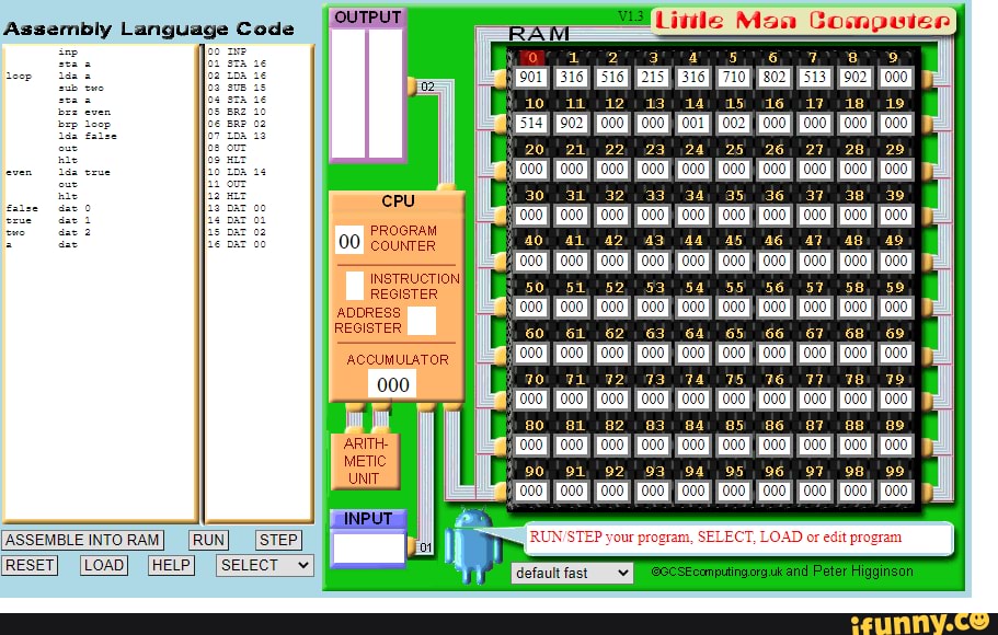 1 1 |
| 8 | NVIDIA GeForce RTX 3080 | Desktop | 65.1 |
| 9 | NVIDIA GeForce RTX 3070 | Desktop | 65.1 |
| 10 | AMD Radeon RX 6700 XT | Desktop | 63.3 |
Comparaciones de CPUs populares
Intel
Xeon Platinum 8170
vs
Intel
Xeon Gold 6154
Intel
Xeon Platinum 8170
vs
Intel
Xeon Gold 6142
Intel
Xeon Platinum 8170
vs
Intel
Xeon Gold 6146
Intel
Xeon Platinum 8170
vs
AMD
EPYC 7643
Intel
Xeon Platinum 8170
vs
AMD
EPYC 7763
AMD
EPYC 7643
vs
Intel
Xeon Gold 6154
AMD
EPYC 7643
vs
Intel
Xeon Gold 6146
AMD
EPYC 7643
vs
AMD
EPYC 7763
AMD
EPYC 7643
vs
AMD
EPYC 7543
AMD
EPYC 7643
vs
Intel
Xeon Platinum 8380
Comparaciones de GPUs populares
AMD
Radeon RX Vega XT
vs
NVIDIA
TITAN V CEO Edition
NVIDIA
TITAN V CEO Edition
vs
NVIDIA
GeForce RTX 3090
NVIDIA
A100 SXM4 40 GB
vs
NVIDIA
TITAN V CEO Edition
NVIDIA
Tesla V100S PCIe 32 GB
vs
NVIDIA
TITAN V CEO Edition
NVIDIA
TITAN V CEO Edition
vs
AMD
Radeon RX 6600
AMD
Radeon RX Vega XT
vs
NVIDIA
GeForce RTX 3090
AMD
Radeon RX Vega XT
vs
NVIDIA
A100 SXM4 40 GB
AMD
Radeon RX Vega XT
vs
NVIDIA
Tesla V100S PCIe 32 GB
AMD
Radeon RX Vega XT
vs
AMD
Radeon RX 6600
Processor / Sudo Null IT News
As far as I can remember, I always dreamed of making a processor. Finally, yesterday I made it. Not God knows what: 8 bit, RISC, the current operating frequency is 4 kHz, but it works. So far, in the logic circuit simulation program, but we all know: “today — on the model, tomorrow — in practice!”.
There are several animations under the cut, a brief introduction to binary logic for the little ones, a short story about the main processor logic chips and, in fact, the circuit.
Binary logic
The binary number system (for those who are not in the know) is a number system in which there are no digits greater than one. This definition confuses many until they remember that in the decimal number system there are no digits greater than nine.
The binary system is used in computers because the numbers in it are easy to encode with voltage: if there is voltage, then one; no voltage means zero. In addition, «zero» and «one» can easily be understood as «false» and «true». Moreover, most of the devices operating in the binary system usually refer to numbers as an array of «truths» and «falsities», that is, they operate with numbers as with logical values. For the smallest and those who are not in the know, I will tell and show how the simplest elements of binary logic work. nine0003
Buffer element
Imagine that you are sitting in your room and your friend is in the kitchen. You shout to him: “Friend, tell me, is there a light on in the corridor?”. The friend replies: “Yes, it’s on fire!” or «No, it’s not on.» Your friend is a buffer between the signal source (the light bulb in the hallway) and the receiver (you). Moreover, your friend is not some ordinary buffer, but a managed buffer. He would be an ordinary buffer if he constantly shouted: «The light is on» or «The light is off.»
Element «Not» — NOT
Now imagine that your friend is a joker who always tells lies. And if the light in the corridor is lit, then he will tell you “No, it’s very, very dark in the corridor,” and if it’s not lit, then “Yes, the light is on in the corridor. ” If you really have such a friend, then he is the embodiment of the “Not” element.
«Or» element — OR
Unfortunately, one light bulb and one friend will not be enough to explain the essence of the “Or” element. You need two light bulbs. So, you have two light bulbs in the hallway — a floor lamp, for example, and a chandelier. You shout: “Friend, tell me, is at least one light in the hallway shining?”, And your friend answers “Yes” or “No”. Obviously, for the answer «No» all the lights must be turned off. nine0003
AND element — AND
The same apartment, you, a friend in the kitchen, a floor lamp and a chandelier in the hallway. To your question “Are both lights on in the corridor?” you get a «Yes» or «No» answer. Congratulations, your friend is now the AND element.
XOR element — XOR
Let’s repeat the experiment once again for the «Or» element, but let’s reformulate our question to a friend: «Friend, tell me, is there only one light bulb in the corridor?». An honest friend will answer “Yes” to such a question only if there is really only one light bulb in the corridor. nine0003
Totalizers
Quarter-totalizer
A quarter-adder is called an XOR element. Why? Let’s figure it out.
Let’s make an addition table for two numbers in the binary system:
0+0=0
0+1=1
1+0= 1
1+1= 10
Now let’s write down the truth table of the XOR element. To do this, let’s designate a luminous bulb as 1, an extinguished bulb as 0, and the friend’s answers «Yes» / «No» as 1 and 0, respectively. nine0005
0 XOR 0 = 0
0 XOR 1 = 1
1 XOR 0 = 1
1 XOR 1 = 0
Very similar, isn’t it? The addition table and the XOR truth table coincide completely, except for one single case. And this case is called «Overflow».
Half adder
When overflowing, the result of the addition no longer fits into the same number of digits as the terms were placed. The terms are two single digits (one significant digit, you know?), and the sum is already two digits (two significant digits). Two digits with one light bulb (“On” / “Off”) can no longer be transmitted. You need two light bulbs. We need to do it! nine0003
In addition to XOR, we need an AND element for the adder.
0 XOR 0 = 0 0 AND 0 = 0
0 XOR 1 = 1 0 AND 1 = 0
1 XOR 0 = 1 1 AND 0 = 0
1 XOR 1 = 0 1 AND 1 = 1
Tadam!
0+0=00
0+1=01
1+0= 01
1+1= 10
Our and the prodigy the half-adder works. It can be considered the simplest specialized processor that adds two numbers. A half-adder is called a half-adder because it cannot take into account the carry (the result of another adder), that is, you cannot add three single-digit binary numbers. In this regard, one multi-bit adder cannot be made from several single-bit half-adders. nine0003
I won’t go into the details of how full and multi-bit adders work, I just hope you get the basic idea.
More complex elements
Multiplexer
I suggest turning on the imagination again. So imagine. You live in a private single-family house, near the door of this house is your mailbox. Going out for a walk, you notice a strange postman who is standing near this very mailbox. And this is what he does: he takes out a bunch of letters from the bag, reads the number on the mailbox, and, depending on the number on the box, throws one or another letter into it. The postman works as a multiplexer. It determines in a certain way (the number on the envelope) which signal (letter) to send along the signal line (mailbox). nine0003
Multiplexers usually consist only of combinations of elements «And», «Or» and «Not». A single-bit multiplexer has one input called «address selection», two inputs with the general name «input signal» and one output, which is called «output signal».
When «address select» is set to 0, the «output signal» becomes the same as the first «input signal». Accordingly, when 1 is applied to the «selection», then the «output signal» becomes equal to the second «input signal».
Demultiplexer
But this thing works exactly the opposite. We give the address to the “choice of address”, we give data to the “data input”, at the output with the number “address” we have data from the input.
Counter
To understand how the counter works, you again need your friend. Call him from the kitchen (I hope he didn’t get bored there, and, most importantly, he didn’t eat all your food), and ask him to do this: let him remember the number 0. Each time you touch him, he must add one to the number that remembers, say the result and remember it. When the result is (let’s say) 3, he should shout «Abracadabra!» and answer at the next touch that now he remembers the number 0. A little difficult? See:
You touch a friend. Friend says «One».
You are touching a friend. Friend says «Two».
You are touching a friend. Friend says «Three». A friend shouts out “ Habrahabr! «. Critical Attack! You are temporarily paralyzed and unable to move.
You are touching a friend. A friend says «Zero».
Well, and so on. Very simple, right?
Of course, you realized that your friend now is a counter. Touching a friend can be considered a «tacting signal» or, simply put, a signal to continue counting. The cry «Abracadabra» indicates that the stored value in the counter is the maximum, and that at the next clock signal the counter will be set to zero. There are two differences between a binary counter and your friend. First, a true binary counter outputs the stored value in binary form. Second: he always does only what you tell him, and never stoops to stupid jokes that can disrupt the operation of the entire processor system. nine0003
Memory
Trigger
Let’s continue to mock your unfortunate (perhaps even imaginary) friend. Now let him remember the number zero. When you touch his left hand, he should memorize the number zero, and when you touch his right hand, the number one. When asked «What number do you remember?» a friend should always answer the number that he remembered — zero or one.
The simplest memory cell is the RS flip-flop (“trigger” means “switch”). The RS flip-flop can store one bit of data («zero» / «one»), and has two inputs. The Set input (just like your friend’s left hand) writes «one» to the trigger, and the Reset input (respectively, the right hand) writes «zero». nine0003
Register
The register is a little more complicated. Your friend turns into a register when you ask him to remember something, and then say «Hey, remind me what I told you to remember?», And the friend answers correctly.
A register can usually store a little more than one bit. It necessarily has a data input, a data output, and a write enable input. From the data output, you can read what is written in this register at any time. At the data input, you can submit the data that you want to write to this register. You can submit data until you get bored. Nothing will be written to the register anyway until one, that is, a “logical unit”, is applied to the write permission input. nine0003
Shift register
Have you ever stood in line? They must have been standing. So you can imagine what it’s like to be data in a shift register. People come and stand at the end of the line. The first person in line enters the office of the big shot. The one who was second in line becomes first, and the one who was third is now second, and so on. The queue is such a tricky shift register, from which “data” (well, that is, people) can run away on business, having previously warned the neighbors in turn. In a real shift register, of course, «data» from the queue cannot escape. nine0003
So, the shift register has a data input (through which data enters the «queue») and a data output (from which the very first entry in the «queue» can be read). The shift register also has a “shift register” input. As soon as a “logical unit” arrives at this input, the entire queue is shifted.
There is one important difference between a queue and a shift register. If the shift register is designed for four entries (for example, four bytes), then the first entry in the queue will reach the exit from the register only after four signals to the “shift register” input. nine0003
RAM
If many, many flip-flops are combined into registers, and many, many registers are combined in one chip, then we get a RAM chip. A memory chip usually has an address input, a bidirectional data input (that is, this input can be written to and read from), and a write enable input. We feed some number to the address input, and this number will select a specific memory cell. After that, at the data input / output, we can read what is written in this very cell. nine0005
Now we will simultaneously apply to the data input / output what we want to write to this cell, and to the write permission input — a “logical unit”. The result is a bit predictable, isn’t it?
Processor
BitBitJump
Processors are sometimes divided into CISC — those that can execute many different instructions, and RISC — those that can execute few instructions, but perform them well. One fine evening, I thought: it would be great if you could make a full-fledged processor that can execute only one instruction. I soon learned that there is a whole class of single-instruction processors — OISC, most often they use the Subleq command (subtract, and if less than or equal to zero, then go) or Subeq (subtract, and if equal to zero, then go). Studying various options for OISC processors, I found on the net the site of Oleg Mazonka, who developed the simplest single-command language BitBitJump. The only command of this language is called BitBitJump (copy a bit and jump to the address). This certainly esoteric language is Turing-complete — that is, it can implement any computer algorithm.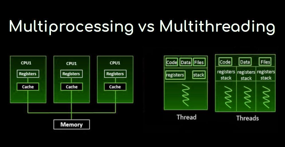 nine0003
A detailed description of BitBitJump and an assembler for this language can be found on the developer’s website. To describe the algorithm of the processor, it is enough to know the following:
1. When the processor is turned on, the PC, A and B registers are written 0
2. We read the memory cell with the address of the PC and save the read into register A
3. Increase PC
4. We read the memory cell with the PC address and save the read into register B
5. Increase PC
6. We write to the cell with the address recorded in register B, the contents of the bit with address A.
7. We read the memory cell with the address of the PC and save the read to register B
8. Write the contents of register B
to the PC register
9. Go to point 2 of our plan
10. PROFIT!!!
Unfortunately, the algorithm is infinite and therefore PROFIT will not be reached.
Actually, scheme
The scheme was built spontaneously, so fear, horror and chaos rule the ball in it. However, it works, and it works well. To turn on the processor, you need:
1. Enter the program into RAM
2. Press switch
3. Set the counter to position 4 (this can also be done in hardware, but the circuit would become even more cumbersome)
4. Turn on the clock generator
As you can see, one register, one shift register, one RAM chip, two binary counters, one demultiplexer (represented by comparators), two multiplexers and some pure logic are used.
You can download the diagram in circ format for the Logisim program and play around. nine0003
What’s next?
First, you can increase the processor capacity by replacing 8-bit elements with 16-bit ones.
Secondly, you can remove the RAM from the processor, and add a simple circuit that will suspend the processor, change the RAM and turn the processor back on. Such a circuit will perform the functions of a simple I / O controller. Then it will be possible to make a calculator, a controller or some other funny useless thing based on this processor.
Thirdly, it is possible to implement this whole scheme in hardware. What am I going to do. As soon as I do, I will definitely tell and show. nine0003
Thank you all for your attention!
P.S. Links (for those too lazy to read):
1. URISC Processors — en.wikipedia.org/wiki/Urisc
2. BitBitJump language site — mazonka.com/bbj/index.html
3. Program for modeling logic circuits Logisim — http://ozark.hendrix.edu/~burch/logisim/
4. Self-made URISC (ORISC) processor for Logisim — narod.ru/disk/313676
/oo.circ.html
Voltage comparator: characteristics and varieties
Acknowledgments
Without the Kuznetsov brothers, the readers would not have had such a wonderful review. It is impossible to ignore the work of the scientific team of the Nizhny Novgorod State University named after N.I. Lobachevsky, its participants, between which:
- Sdobnyakov V.V.
- Karzanov V.V.
- Shabanov V.N.
- Reviewers: Dorokhin M.
 V. and Zdoroveyshchev A.V.
General information
A comparator compares two voltages, hence the name. If necessary, either a conditional signal is generated in the form of a binary code, or the sign of the difference is given in another way:
- A steep voltage drop (slope or slope).
- Impulse with specified characteristics.
- Output voltage polarity reversal.
- The binary code in the system logic of this chipset.
The comparator is territorially included in the analog-to-digital converter, and can be used separately. Accuracy directly depends on the element, as well as on bit depth. The characteristics of the comparator include:
- Sensitivity.
- Performance.
- Cost.
- Durability.
- Stability.
- Load capacity.
- Input impedance, etc.
Most comparators are implemented on the basis of operational amplifiers, the data in the reference books are given jointly. This is achieved through the introduction of feedback, which was invented in the 30s of the XX century.
Characteristics of comparators
Comparator sensitivity refers to the minimum voltage that can be sensed. Differential pairs of transistors used in operational amplifiers increase temperature stability, therefore they are used to create comparators. The parameter is closely related to resolution or accuracy. Sensitivity is highly dependent on the circuit design, this is an obvious fact. nine0003
In addition to thermal stability and architecture, the parameter is affected by noise immunity and reliability. In practice, sensitivity is considered optimal, equal to half the digit of the analog-to-digital converter. This means that due to the comparator, the accuracy of the measurement is not reduced. At the present stage of technology development, these are sometimes very different values.
The speed of digital technology is great, but given the fact that the converter needs to have time to make a sample, the processor clock frequency should be hundreds, if not thousands of times higher than the sampling resolution.
And the main limiting factor is the speed characteristics of the comparator. At its second input, at the moment of measurement, the reference voltage gradually increases until a match is reached. And a digital result code is generated. nine0003
The sampling frequency is determined by the speed qualities of the process under study. If it’s in the audio range, values start at 45kHz and can be four times that for a studio recording. At each time interval, the comparator must have time to compare the voltage, the minimum processor frequency to obtain an accuracy of 0.5% lies already in the 10 MHz region. In practice, much larger values \u200b\u200bare observed, but remember, the main bus of the motherboard becomes the fastest section of the system unit (personal computer). nine0003
The speed of the comparator is expressed as the time between adjacent measurements. It consists of the interval of increasing the compared voltage to the desired level and the speed of the electronic components. The last figures include the period from the comparator’s decision to issue a signal pulse to its actual appearance at the outputs. The second parameter is the steepness of the pulse front, since the logic of the microcircuits is tuned to the thresholds. The recovery time for which the comparator returns to its original state is considered important. nine0003
The specified parameters together determine the clock frequency of the comparator itself. Load capacity refers to the ability to deliver a signal strong enough to operate dependent circuits. Distinguish the so-called overload capacity, showing how great the difference in voltage is sometimes on adjacent readings. To reduce the measurement intervals, starting from the second, the comparator can carry out two parallel measurement processes:
- Increase in voltage compared to the previous reading. nine0200
- Decrease in voltage compared to the previous reading.
This way you can quickly find the result without going through the entire range from the beginning. Although it will take as many as two comparators connected in parallel. But the time savings are worth the struggle. The success of such an event is directly affected by the overload capacity.
The input resistance forms a resistive divider with the signal source, and the smaller it is, the higher the accuracy, most of the voltage drops here. As the parameter increases, the current consumption also decreases. For most comparators, the input impedance is adjusted to suit specific needs, for individual circuits. nine0003
Comparator Varieties
Most comparators are based on op-amp circuits surrounded by a positive feedback circuit. Due to the large gain, it is possible to achieve a sheer transfer function of the cascade.
The characteristic of the operational amplifier is linear in a certain area. The graph is symmetrical around zero. At a certain value of Ulimit, saturation occurs and the output voltage does not increase further. This is observed in the positive area of the input values and in the negative. The described property is used to build comparators. nine0003
The operational amplifier is covered by a positive connection, with its transfer coefficient inversely proportional to the gain of the operational amplifier, the formula goes to infinity. The steepness of the graph depends on the specified parameter, it becomes vertical. What is required in practice to compare voltages.
Any value is allowed by the reference. For example, it is possible to implement a zero-crossing voltage circuit. But as part of an analog-to-digital converter, the measured value within the interval is considered constant, the reference voltage increases until it equals. And at this moment, a coincidence impulse is generated. nine0003
Threshold comparator
Threshold voltage comparator — mentioned in the literature. Its transfer characteristic is unambiguous — when the difference at the inputs of the operational amplifier becomes equal to zero, a response occurs at the output. The reverse movement along the transfer characteristic follows the same trajectory.
It is organized as above, with an op-amp looped around to produce a steep, sheer transfer characteristic. But some small error remains. The reference voltage is usually applied to a non-inverting input. nine0003
Hysteresis comparator
The hysteresis comparator got its name because the gain of the feedback loop changes in absolute value and in sign. As a result, a family of transfer characteristics is obtained, which makes it possible to create a comparator that turns on according to one voltage value, and turns off according to another.
The device is useful in case of high-frequency interference on the line. And when the value changes many times over a given measurement interval, it is easy for a conventional voltage comparator to miss. At the same time, the hysteresis will correctly evaluate up to noise and hold the signal at the output until the process under study is close to the standard. nine0003
Any real comparator is considered hysteretic due to the presence of an error, some types specially have an extended loop due to the described nuances. A pronounced rectangular characteristic is characterized by the Schmitt trigger. Its hysteresis transfer function can be used to build a comparator. Due to the presence of positive feedback, the Schmitt trigger characteristic has a noticeable steepness.
Already for analog circuits, the sensitivity threshold reached 5-10 mV, which is enough in most cases. Since the response time of the Schmitt trigger is reduced to 0.1 µs, it becomes possible to evaluate signals with a frequency of hundreds of kHz (much higher than ultrasound). The trigger shown in the figure is characterized by a large temperature drift and a small measurement range. nine0003
Diode balanced regenerative circuits are popular for simplicity. Feedback here is done through a transformer. By using the middle operating point, it becomes possible to produce both positive and negative feedback at the same time. Compared voltages are applied to the cathodes of the diodes (n-region, in the area of which a perpendicular line is drawn). The operating point of the transistor is chosen at the beginning of the current-voltage characteristic, the base current is calculated so that saturation does not occur. nine0003
The capacitor isolates the base and the input circuit. If the diode D1 is locked, and D2 is open, negative feedback works. As a result, generation does not occur. Otherwise, the blocking generator produces the first pulse. Its positive front indicates that the standard has caught up with the estimated value. The sensitivity of the balanced regenerative circuit can reach 1 mV.
Comparators based on tunnel diodes are good for small dimensions, excellent speed, low noise level, low switching power thresholds. The mechanical strength and resistance of semiconductors are well known. Tunnel diodes are considered rare devices that are not afraid of radiation, which makes them popular in special applications. In addition, the resistance of such comparators is extremely small, which reduces the sensitivity. nine0003
The characteristic of the tunnel diode contains a section with a negative differential resistance, which allows you to implement the desired transfer function. The obvious disadvantage of the scheme is the low accuracy. The current-voltage characteristic of the tunnel diode is too flat. But in terms of simplicity, this comparator cannot be compared with any other type of device. It cannot yet be called hysteresis; to obtain this type of characteristic, at least two tunnel diodes are required. nine0003
The simplest comparator
Using two tunnel diodes, it is easy to build a simple comparator, including them in a twin circuit. The elements are assumed to be identical. The transfer characteristic of the system is highly dependent on the supply voltage of the circuit. Characteristics are easily changed, which leads to great application flexibility. The sensitivity is measured by current, and the experimentally obtained values lie in the region of 8 μA at a clock frequency of 200 MHz, 3 μA at 50 MHz.