PCIe Gen 4 vs. Gen 3 Slots, Speeds
Photo: In this blog post, we’ll go over the differences between PCIe Gen 4 and PCIe Gen 3. We’ll also discuss whether it’s time for an upgrade.
Table of Contents
- What is PCI Express?
- How fast is PCIe 4.0 vs. PCIe 3.0?
- Are PCIe 4.0 and PCIe 3.0 backward and forward compatible?
- How does PCIe 4.0 influence SSD and GPU selection?
- Is upgrading to PCIe 4.0 worth it?
Make no mistake, PCIe 4.0 is twice as fast as PCIe 3.0.
But whether it’s time to upgrade your hardware to support PCIe Gen 4 is a different matter altogether.
In this blog post, we’ll discuss the speed differences between both generations and address backward and forward compatibility.
Then, we’ll touch on whether upgrading is right for you.
You can read more about PCI Express, how it works and its previous generations below, or you can skip right to the speed differences between PCIe 4. 0 and PCIe 3.0.
Photo: Seven PCIe slots showcased on a Trenton Systems’ dual Xeon Motherboard. This particular motherboard incorporates three PCIe 3.0 x16 slots and four PCIe 3.0 x8 slots for super fast speeds and versatile system expansion. At Trenton Systems, we design our own boards to fit your application-specific needs. Get in touch with us today.
What is PCI Express?
The Peripheral Component Interconnect Express (PCI Express or PCIe) is a high-speed interface standard for connecting additional graphics cards (GPUs), Local Area Network (LAN) ports, NVME solid-state drives (SSDs), Universal Serial Bus (USB) ports and other hardware to a computer’s motherboard.
This is accomplished using expansion cards, also known as add-on cards.
Simply put, the PCI Express interface allows for the expansion of a motherboard beyond its default GPU, network and storage configurations.
The Peripheral Component Interconnect Special Interest Group (PCI-SIG), comprised of big-name technology companies like Intel, IBM, Dell, HP, AMD and NVIDIA, introduced the first generation of PCI Express, entitled PCIe 1. 0, in 2003.
PCIe 2.0 and 3.0 were released in 2007 and 2010, respectively. PCIe 4.0 came out in 2017, and PCI-SIG’s latest generation, PCIe 5.0, debuted in 2019.
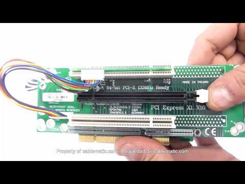
The PCI Express interface is actualized through PCIe slots, which vary in type depending on a motherboard’s chipset.
The slots differ in both length and speed based on their number of lanes (at a minimum, one lane, and at a maximum, 16 lanes).
Slots are available in one-lane, two-lane, four-lane, eight-lane and 16-lane configurations, usually expressed as PCIe x1, x2, x4, x8 or x16.
Photo: A motherboard showcasing the different PCIe slot configurations, as well as Peripheral Component Interconnect (PCI) slots, which are now obsolete. Credit: CCBoot
For example, PCIe 3.0 x4 refers to a Gen 3 expansion card or slot with a four-lane configuration.
Likewise, PCIe 4.0 x16 refers to a Gen 4 expansion card or slot with a 16-lane configuration.
And so on.
Each new PCI Express generation doubles the amount of bandwidth each slot configuration can support. That’s why the configurations are expressed in multiples of two.
| PCI Express: Unidirectional Bandwidth in x1 and x16 Configurations | ||||
| Generation | Year of Release | Data Transfer Rate | Bandwidth x1 | Bandwidth x16 |
| PCIe 1.0 | 2003 | 2.5 GT/s | 250 MB/s | 4.0 GB/s |
| PCIe 2.0 | 2007 | 5.0 GT/s | 500 MB/s | 8.0 GB/s |
| PCIe 3.0 | 2010 | 8.0 GT/s | 1 GB/s | 16 GB/s |
| PCIe 4.0 | 2017 | 16 GT/s | 2 GB/s | 32 GB/s |
| PCIe 5.0 | 2019 | 32 GT/s | 4 GB/s | 64 GB/s |
| PCIe 6.0 | 2021 | 64 GT/s | 8 GB/s | 128 GB/s |
Table: PCI-SIG introduced the first generation of PCI Express in 2003.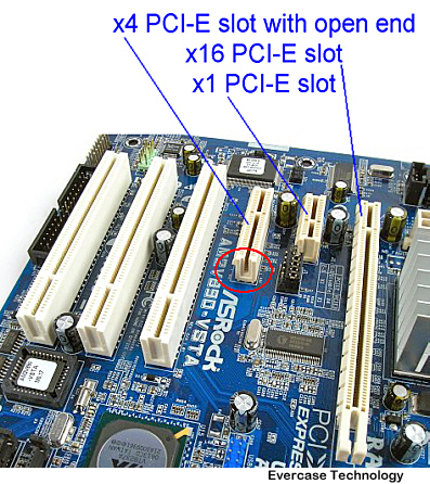 With each new generation comes a doubling of data transfer rate and total bandwidth per lane configuration, the latter of which is expressed in both unidirectional and bidirectional measurements, depending on the source. To find the total unidirectional bandwidth for each lane configuration, simply multiply the x1 bandwidths listed in the table above by two, four, eight or 16. Multiply the number resulting from that calculation by two to calculate total bidirectional bandwidth. Source: PCI-SIG
For example, PCIe 1.0 has a 250 MB/s bandwidth in the one-lane configuration, a 0.500 GB/s bandwidth in the two-lane, a 1 GB/s bandwidth in the four-lane, a 2 GB/s bandwidth in the eight-lane and a 4.0 GB/s bandwidth in the 16-lane.
It’s important to note as well that these lane-specific bandwidths are often doubled to account for bidirectional travel, or data traveling to and from each lane.
Furthermore, each new generation of PCIe typically doubles its predecessor’s data rate and bandwidth for each configuration.
For example, PCIe 1.0 has a 2.5 GT/s data rate and a 250 MB/s bandwidth in the one-lane configuration, while the one-lane configuration for PCIe 2.0 supports a 5.0 GT/s data rate and a 500 MB/s bandwidth, and so forth.
But PCIe 1.0 and PCIe 2.0 are outdated.
Today, PCIe 3.0 is a motherboard standard, at least until the industry universally adopts PCIe 4.0 and eventually PCIe 5.0. And by that point, PCI-SIG will have rolled out the next generation, PCIe 6.0, which is expected in 2021.
As with any new technology, it can take computer hardware manufacturers some time to begin standardizing their motherboards with the latest PCI Express generation.
How fast is PCIe 4.0 vs. PCIe 3.0?
PCIe 4.0 is twice as fast as PCIe 3.0.
PCIe 4.0 has a 16 GT/s data rate, compared to its predecessor’s 8 GT/s. In addition, each PCIe 4.0 lane configuration supports double the bandwidth of PCIe 3.0, maxing out at 32 GB/s in a 16-lane slot, or 64 GB/s with bidirectional travel considered.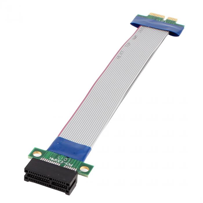
| Unidirectional Bandwidth: PCIe 3.0 vs. PCIe 4.0 | ||||
| PCIe Generation | x1 | x4 | x8 | x16 |
| PCIe 3.0 | 1 GB/s | 4 GB/s | 8 GB/s | 16 GB/s |
| PCIe 4.0 | 2 GB/s | 8 GB/s | 16 GB/s | 32 GB/s |
Table: The speed differences between PCIe 4.0 and PCIe 3.0 in each lane configuration.
Let’s use the 16-lane slot configuration to put the speed differences between PCIe 4.0 and 3.0 into perspective and make all this computer lingo a little more relatable.
For the purposes of this analogy, we’ll employ unidirectional bandwidth for both generations.
Photo: Aerial drone photograph of traffic in a metropolitan area, used to illustrate PCIe lanes.
Imagine 16 lanes of cars (data) traveling in 16 adjacent lanes (configuration) on the major PCIe 3. 0 Highway (generation).
The cars are traveling at the posted PCIe 3.0 speed limit of 15 miles per hour (bandwidth).
Several miles in the opposite direction, however, the state (PCI-SIG) has just opened the PCIe 4.0 Highway and doubled the speed limit.
The cars on this highway are traveling faster at the newly posted PCIe 4.0 speed limit of 30 miles per hour.
And a couple of years from now, cars will be cruising on the PCIe 5.0 Highway, where they’ll be allowed to travel at a posted speed limit of 60 miles per hour.
And so on with each new PCI Express generation that PCI-SIG introduces.
Photo: Wooden backward and forward signposts. Credit: Hashnode
Are PCIe 4.0 and PCIe 3.0 backward and forward compatible?
Both PCIe 4.0 and PCIe 3.0 are backward and forward compatible.
Remember those high-speed components (GPUs, NVME SSDs, etc.) that use PCIe slots to interface with the motherboard and provide additional functionality?
Thanks to backward and forward compatibility, the new can be used with the old (backward compatibility), and the old can be used with the new (forward compatibility).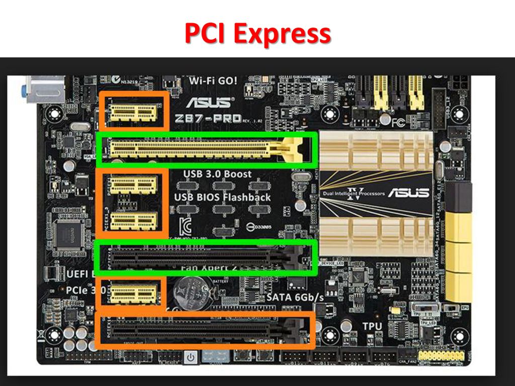
For example, a PCIe 4.0 graphics card can be inserted into a motherboard’s PCIe 3.0 slot; however, the Gen 4 card’s bandwidth would be bottlenecked by the Gen 3 slot’s bandwidth limitations.
Similarly, a PCIe Gen 3 graphics card can be inserted into a motherboard’s PCIe Gen 4 slot, but the Gen 3 graphics card will be incapable of fully utilizing the higher bandwidth capabilities of the Gen 4 slot due to the card’s intrinsic bandwidth limitations.
Photo: Connectors of different-sized PCIe expansion cards. Credit: How-To Geek
Your expansion card doesn’t have to be installed on a slot with the same number of lanes, either.
For example, a PCIe 4.0 SSD with four lanes can be inserted into a x16 slot.
But the inverse doesn’t work.
So, a PCIe 3.0 x16 graphics card won’t fit in a x1, x2, x4 or x8 slot.
In short, the slot into which the expansion card is being inserted must have an equal or greater number of lanes.
Otherwise, the card can’t physically be inserted into the slot.
Photo: There are a few things to keep in mind when choosing PCIe 4.0 SSDs and PCIe 4.0 GPUs, mainly the population and PCIe generation of your motherboard’s PCIe slots.
How does PCIe 4.0 influence SSD and GPU selection?
As previously mentioned, PCIe 4.0 is backward and forward compatible. So, you can insert a PCIe 4.0 GPU into a PCIe 3.0 slot, but you’ll be bottlenecked by the bandwidth limitations of Gen 3. In other words, you won’t be able to take full advantage of the increased speeds of that awesome PCIe 4.0 GPU. The same goes for PCIe SSDs, so keep this in mind when you’re shopping around.
Photo: An 512GB PCIe-based NVMe M.2 SSD
PCIe 4.0 SSD
If you’re in the market for a high-speed PCIe 4.0 SSD, such as an PCIe 4.0 NVMe SSD, take comfort in knowing that you’ll have the access to the latest and greatest that the PCIe specification has to offer with Gen 4, including increased data transfer rates, bandwidth, and decreased latency on the PCIe bus. This is assuming, of course, that your motherboard is equipped with PCIe Gen 4 slots into which you can insert these PCIe 4.0 SSDs.
Remember: the PCIe generation used on your motherboard’s PCIe slots determines the data transfer rate and bandwidth of whatever expansion card you insert into it. PCIe 4.0 SSDs can only match the speeds of a PCIe 4.0 slot, and PCIe 3.0 SSDs can’t leap in data transfer rate and bandwidth to PCIe 4.0. So, if you insert any PCIe 4.0 SSDs into previous-generation PCIe slots, you won’t receive the bandwidth and data transfer rate increases you’re expecting from PCIe 4.0, only the bandwidth and data transfer rate of that slot’s particular PCIe generation.
There’s also widespread use of PCIe 4.0 NVMe SSDs, specifically, mainly because NVMe has become the industry standard for PCIe SSDs, but also because NVMe SSDs reduce power consumption, further reduce latency, and incorporate 1,000,000 input/output operations per second (IOPS) compared to a SATA SSD’s 200,000. This offers an obvious performance increase to users shopping around for PCIe 4.0 SSDs.
Photo: A GPU
PCIe 4.0 GPU
The same bandwidth and data transfer rate rules that apply to PCIe 4.0 SSDs apply to PCIe 4.0 GPUs. If you purchase a PCIe 4.0 GPU for your system and seek to benefit from PCIe Gen 4’s performance increases and reduced latency, then your motherboard will need to be populated with a PCIe 4.0 slot of appropriate lane size to support your PCIe 4.0 GPU.
Otherwise, your PCIe 4.0 GPU will be stuck with previous-generation speeds, and who wants to purchase a new, shiny, expensive PCIe 4.0 GPU without, you know, reaping the benefits of PCIe 4.0?
We’re starting to see more and more PCIe 4.0 GPUs pop up on the market, and it’s clear that they’ll play a pivotal role in streamlining and boosting the performance of data-intensive artificial intelligence (AI) and machine learning (ML) applications of the future. But the last thing you want to do is purchase one for your system and find out it’s useless.
Photo: Depending on the data transfer rate and bandwidth needs of your program or application, it may be time to upgrade to PCIe 4.0.
Is upgrading to PCIe 4.0 worth it?
PCIe 4.0 supports double the bandwidth of PCIe 3.0, so if you want to take advantage of the bandwidth capabilities of that PCIe 4.0 expansion card you just purchased, then you’ll need PCIe 4.0 slots on your motherboard.
It’s as simple as that.
But if you’re comfortable with a certain degree of bandwidth limitation and don’t want to spend the money to upgrade to a PCIe 4.0 motherboard, then upgrading to Gen 4 probably won’t be worth it to you.
Plus, if you’re working with PCIe 3.0 expansion cards and slots, anyway, and they’re providing you with the speeds that your application needs, then don’t worry about upgrading to Gen 4.
When deciding whether to upgrade, ask yourself two key questions:
- Are my current PCI Express cards and slots providing me with the speeds I need for my application? If yes, don’t upgrade.
 If no, consider upgrading.
 - Will my application need a bandwidth boost soon to keep up with its increasing input/output workload? If yes, consider upgrading. If no, don’t upgrade.
Contact Trenton Systems today or chat with a member of our team to discuss whether upgrading is right for you.
Be sure to subscribe to our blog to keep up with the latest updates.
Trenton Systems creates rugged computer systems to help customers around the world meet their rugged computing needs. We stress-test our computer systems to the max, ensuring that customers can carry out industry-specific operations comfortably, effectively and smack dab in the middle of the world’s harshest conditions. In other words, we stress so you don’t have to.
What Is PCIe? A Basic Definition
PCIe slot (Image credit: MMXeon/Shutterstock)
PCIe (peripheral component interconnect express) is an interface standard for connecting high-speed components. Every desktop PC motherboard has a number of PCIe slots you can use to add GPUs (aka video cards aka graphics cards), RAID cards , Wi-Fi cards or SSD (solid-state drive) add-on cards. The types of PCIe slots available in your PC will depend on the motherboard you buy .
PCIe slots come in different physical configurations: x1, x4, x8, x16, x32. The number after the x tells you how many lanes (how data travels to and from the PCIe card) that PCIe slot has. A PCIe x1 slot has one lane and can move data at one bit per cycle. A PCIe x2 slot has two lanes and can move data at two bits per cycle (and so on).
(Image credit: Erwin Mulialim/Wikimedia Commons)
You can insert a PCIe x1 card into a PCIe x16 slot, but that card will receive less bandwidth. Similarly, you can insert a PCIe x8 card into a PCIe x4 slot, but it’ll only work with half the bandwidth compared to if it was in a PCIe x8 slot. Most GPUs require a PCIe x16 slot to operate at their full potential.
PCIe Generations Compared
| Bandwidth | Gigatransfer | Frequency | |
| PCIe 1.0 | 8 GB/s | 2.5 GT/s | 2.5 GHz |
PCIe 2. 0 0 |
16 GB/s | 5 GT/s | 5 GHz |
| PCIe 3.0 | 32 GB/s | 8 GT/s | 8 GHz |
| PCIe 4.0 | 64 GB/s | 16 GT/s | 16 GHz |
| PCIe 5.0 | 128 GB/s | 32 GT/s | 32 GHz |
| PCIe 6.0 | 256 GB/s | 64 GT/s | 32 GHz |
Current PCIe Generations
PCIe standards currently come in five different generations: PCIe 1.0, PCIe 2.0, PCIe 3.0, PCIe 4.0 and PCIe 5.0. Bandwidth doubles with each generation.
How do you know what performance you’ll get with a PCIe expansion card? Your PCIe card will run at the lowest generation present. So if you put a PCIe 2.0 card in a PCIe 3.0 slot, you’ll get PCIe 2.0 performance.
PCIe 4.0
The PCIe 4.0 standard debuted in 2017 and offers 64 GBps of throughput. It’s available for enterprise-grade servers, but only became usable with SSDs in 2019. The AMD Ryzen 3000-series CPUs that debuted in July 2019 were the first desktop CPUs to support PCIe 4. 0 x16 out of the box. For full support, users will need new motherboards running the X570 chipset .
To learn more about PCIe 4.0, check out our article What We Know About PCIe 4.0 So Far.
PCIe 5.0
The official PCIe 5.0 standard came out in May 2019. It will bring 128 GBps of throughput. The specification is backwards compatible with previous PCIe generations and also includes new features, including electrical changes to improve signal integrity and backward-compatible CEM connectors for add-in cards. Intel was the first to embrace the PCIe 5.0 on the CPU side with its Alder Lake platform. However, the first PCIe 5.0 devices are expected to debut in for enterprise customers in 2022, with consumer offerings to follow.
PCI-SIG, which defines PCIe standards, expects PCIe 4.0 and PCIe 5.0 to co-exist for a while, with PCIe 5.0 used for high-performance needs craving the most throughput, like GPUs for AI workloads and networking applications.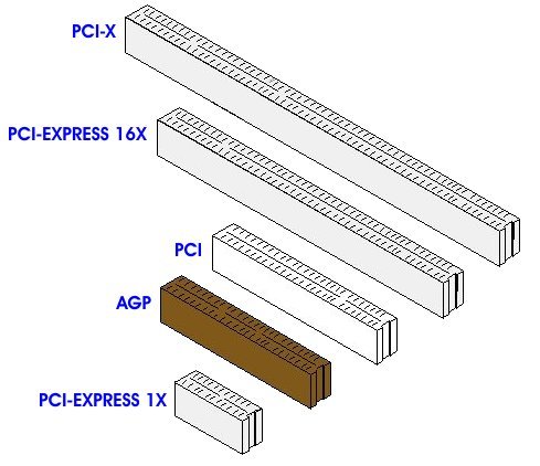 So, PCIe 5.0 will mainly be used in data center, networking and high-performance computing (HPC) enterprise environments, while less-intense applications, like those used by desktop PCs, will be fine with PCIe 4.0.
Future PCIe Generations: PCIe 6.0
PCIe 6.0
PCIe 6.0 spec (Image credit: PCI-SIG)
In June 2019, PCI-SIG said it will release the standards for PCIe 6.0 in 2021 (the spec is currently in revision 0.7 ) . We don’t expect to see products until at least the end of 2022, if not 2023.
PCIe 6.0 will double the bandwidth of PCIe 5.0 to 256 GB/s among the same maximum number of lanes, 16. Data transfer rate will hit 64 GT/s per pin, up from PCIe 5.0’s 32 GT/s. PCIe 6.0 is also expected to be backwards compatible with previous PCIe generations.
This article is part of the Tom’s Hardware Glossary .
Further reading:
- Dissecting the Modern Motherboard: Connectors, Ports & Chipsets Explained
- How to Choose a Motherboard
- Best Motherboards
Scharon Harding has a special affinity for gaming peripherals (especially monitors), laptops and virtual reality.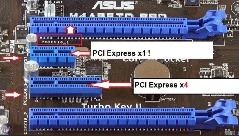 Previously, she covered business technology, including hardware, software, cyber security, cloud and other IT happenings, at Channelnomics, with bylines at CRN UK.
Topics
Components
Motherboards
PCI Express Bandwidth Test: PCIe 4.0 vs. PCIe 3.0 Gaming Performance & Limited VRAM Memory Buffers
This month AMD will finally release their first entry-level RDNA2-based gaming product, the Radeon RX 6500 XT. This new GPU is set to come in at a $200 MSRP, though of course we expect it to cost more than that beyond an initial limited run, which may hit close to the MSRP. In reality, the 6500 XT is probably going to end up priced between $300 to $400 at retail, but we’ll have to wait and see on that one.
It’s been widely reported that the 6500 XT is restricted to PCI Express 4.0 x4 bandwidth and although AMD hasn’t made that public yet, and we’re bound by an NDA, this was already confirmed by Asrock, so it’s no longer a secret. But what might this mean for the Radeon RX 6500 XT? Opinions are divided on this one. Some of you believe this will cripple the card, while others point to PCI Express bandwidth tests using flagship graphics cards which suggest the 6500 XT will be fine, even in a PCI Express 3.0 system.
With PCIe 4.0 you get roughly 2 GB/s of bandwidth per lane, giving the 6500 XT a ~8 GB/s communication link with the CPU and system memory. But if you install it in a PCIe 3.0 system that figure is halved, and this is where you could start to run into problems.
| Unidirectional Bandwidth: PCIe 3.0 vs. PCIe 4.0 | ||||
| PCIe Generation | x1 | x4 | x8 | x16 |
| PCIe 3.0 | 1 GB/s | 4 GB/s | 8 GB/s | 16 GB/s |
PCIe 4. 0 0 |
2 GB/s | 8 GB/s | 16 GB/s | 32 GB/s |
The folks over at TechPowerUp have tested an RTX 3080 with average frame rate performance at 1080p only dropping ~10% when limited to 4 GB/s of PCIe bandwidth. With that being a significantly more powerful GPU, many have assumed the 6500 XT will be just fine. The problem with that assumption is that you’re ignoring that the RTX 3080 has a 10GB VRAM buffer, while the 6500 XT only has a 4GB VRAM buffer. The smaller the memory buffer, the more likely you are to dip into system memory, and this is where the limited PCIe bandwidth can play havoc.
The smaller the memory buffer, the more likely you are to dip into system memory, and this is where the limited PCIe bandwidth can play havoc.
Of course, the RTX 3080 was tested using ultra quality settings whereas the 6500 XT is more suited to dialed down presets, such as ‘medium’, for example. AMD themselves would argue that the PCIe 3.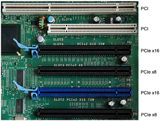 0 bandwidth won’t be an issue for the 6500 XT as gamers should ensure they’re not exceeding the memory buffer for optimal performance, but with a 4GB graphics card in modern games that’s very difficult.
We’ll discuss more about that towards the end of this review, but for now let’s explain what we’re doing here. Although 6500 XT reviews are only days away, we decided not to wait. Initially our idea was to investigate PCIe performance with a similar spec product for our internal reference, but the results were so interesting that we decided to make a full feature out of it.
| PCI Express: Unidirectional Bandwidth in x1 and x16 Configurations | ||||
| Generation | Year of Release | Data Transfer Rate | Bandwidth x1 | Bandwidth x16 |
| PCIe 1.0 | 2003 | 2. 5 GT/s 5 GT/s |
250 MB/s | 4.0 GB/s |
| PCIe 2.0 | 2007 | 5.0 GT/s | 500 MB/s | 8.0 GB/s |
| PCIe 3.0 | 2010 | 8.0 GT/s | 1 GB/s | 16 GB/s |
| PCIe 4.0 | 2017 | 16 GT/s | 2 GB/s | 32 GB/s |
| PCIe 5.0 | 2019 | 32 GT/s | 4 GB/s | 64 GB/s |
| PCIe 6.0 | 2021 | 64 GT/s | 8 GB/s | 128 GB/s |
To gather some insight into what this could mean for the 6500 XT, we took the 5500 XT and benchmarked several configurations. First, I tested both the 4GB and 8GB versions using their stock PCIe 4.0 x8 configuration, then repeated the test with PCIe 4.0 x4. This is the same configuration the 6500 XT uses, and then again with PCIe 3. 0 x4.
0 x4.
We’ve run these in a dozen games at 1080p and 1440p and for the more modern titles we’ve gone with the medium quality preset, which is a more realistic setting for this class of product. We’ll go over the data for most of the games tested and then we’ll do some side by side comparisons. Testing was performed in our Ryzen 9 5950X test system, changing the PCIe mode in the BIOS.
Given the 6500 XT and 5500 XT are expected to be fairly close in terms of performance based on benchmark numbers released by AMD, using the 5500 XT to simulate the potential PCIe issues of the 6500 XT should be fairly accurate. We’ll make the disclaimer that the 6500 XT is based on more modern RDNA2 architecture and this could help alleviate some of the PCIe bandwidth issues, though I’m not expecting that to be the case, we’ll keep the architectural difference in mind.
Benchmarks
Starting with F1 2021, we see that limiting the PCIe bandwidth with the 8GB 5500 XT has little to no impact on performance. Then for the 4GB model we are seeing a 9% reduction in 1% low performance at a 6% hit to the average frame rate when comparing the stock PCIe 4.0 x8 configuration of the 5500 XT to PCIe 3.0 x4.
That’s not a massive performance hit, but it’s still a reasonable drop for a product that’s not all that powerful to begin with, though it does perform well in F1 2021 using the high quality preset.
Jumping up to 1440p we see no real performance loss with the 8GB model, whereas the 4GB version drops ~12% of its original performance. This isn’t a significant loss in the grand scheme of things and the game was perfectly playable, but for a card that’s not exactly packing oodles of compute power, a double-digit performance hit will likely raise an eyebrow.
Things get much much worse in Shadow of the Tomb Raider. A couple of things to note here… although we’re using the highest quality preset for this game, it was released back in 2018 and with sufficient PCI Express bandwidth, the 5500 XT can easily drive 60 fps on average, resulting in an enjoyable and very playable experience.
We see that PCIe bandwidth is far less of an issue for the 8GB model and that’s because the game does allocate up to 7 GB of VRAM using these quality settings at 1080p.
The 4GB 5500 XT plays just fine using its stock PCIe 4.0 x8 configuration, there were no crazy lag spikes, the game was very playable and enjoyable under these conditions. Even when limited to PCIe 4.0 x4 bandwidth, we did see a 6% drop in performance, though overall the gameplay was similar to the x8 configuration. If we then change to the PCIe 3.0 spec, performance tanks and while still technically playable, frame suffering becomes prevalent and the overall experience is quite horrible.
We’re talking about a 43% drop in 1% low performance for the 4GB model when comparing PCIe 4.0 operation to 3.0, which is a shocking performance reduction.
You could argue that we’re exceeding the VRAM buffer here, so it’s not a realistic test, but you’ll have a hard time convincing me of that, given how well the game played using PCIe 4. 0 x8.
0 x8.
As you’d expect, jumping up to 1440p didn’t help and we’re still looking at a 43% hit to the 1% lows. When using PCI Express 4.0, the 4GB model was still able to deliver playable performance, while PCIe 3.0 crippled performance to the point where the game is simply not playable.
Resident Evil Village only requires 3.4 GB of VRAM in our test, so this is a good example of how these cards perform when kept within the memory buffer. We’re using the heavily dialed down ‘balanced’ quality preset, so those targeting 60 fps on average for these single player games will have some headroom to crank up the quality settings, though as we’ve seen you’ll run into performance related issues much sooner when using PCIe 3.0 with a x4 card.
Speaking of which, we have a great example of that at 1440p which in our test pushed memory allocation up to 4.8 GB with usage around 4 GB. PCI Express bandwidth aside, the 4GB buffer alone crippled the 5500 XT here, and reducing the bandwidth to x4 destroys performance to the point where the card can no longer be used.
Rainbow Six Siege is another example of why heavily limiting PCI Express bandwidth of cards with smaller VRAM buffers is a bad idea. The 4GB 5500 XT is already up to 27% slower than the 8GB version, with the only difference between the two models being VRAM capacity.
But we see that limiting the PCIe bandwidth has a seriously negative impact on performance of the 4GB model. Halving the bandwidth from x8 to x4 in the 4.0 mode drops the 1% low by 21%. This is particularly interesting as it could mean even when used in PCIe 4.0 systems, the 6500 XT is still haemorrhaging performance due to the x4 bandwidth.
But it gets much worse for those of you with PCIe 3.0 systems, which at this point in time is most, particularly those seeking a budget GPU. Here we’re looking at a 52% drop in performance from the 4.0 x8 configuration to 3.0 x4. Worse still, 1% lows are not below 60 fps and while this could be solved by reducing the quality settings, the game was perfectly playable even with 4GB of VRAM when using the PCIe 4. 0 x8 mode.
As you’d expect, it’s more of the same at 1440p, we’re looking at 1% lows that are slashed in half on the 4GB card when using PCI Express 3.0.
Moving on to Cyberpunk 2077, we tested using the medium quality preset with medium quality textures. This game is very demanding even using these settings, but with the full PCIe 4.0 x8 mode the 4GB 5500 XT was able to deliver playable performance with an average of 49 fps at 1080p. But when reducing the bus bandwidth with PCIe 3.0 x4, performance tanked by 24% and now the game is barely playable.
The 1440p data isn’t that relevant as you can’t really play Cyberpunk 2077 with a 5500 XT at this resolution using the medium quality settings, but here’s the data anyway.
We tested Watch Dogs: Legion using the medium quality preset and although the 4GB model is slower than the 8GB version as the game requires 4.5 GB of memory in our test using the medium quality preset, performance was still decent when using the standard PCIe configuration with 66 fps on average. Despite the fact that we must be dipping into system memory, the game played just fine.
However, reducing the PCIe bandwidth had a significant influence on performance and we see that PCIe 4.0 x4 dropped performance by 24% with PCIe 3.0 x4, destroying it by a 42% margin.
We’ve heard reports that the upcoming 6500 XT is all over the place in terms of performance, and the limited 4GB buffer along with the gimped PCIe 4.0 x4 bandwidth is 100% the reason why and we can see an example of that here at 1080p with the 5500 XT.
The PCIe 3.0 x4 mode actually looks better at 1440p relative to the 4.0 spec as the PCIe bandwidth bottleneck is less severe than the compute bottleneck at this resolution. Still, we’re talking about an unnecessary 36% hit to performance.
Assassin’s Creed Valhalla has been tested using the medium quality preset and we do see an 11% hit to performance for the 8GB model when using PCIe 3.0 x4, so that’s interesting as the game only required up to 4. 2 GB in our test at 1080p.
That being the case, the 4GB model suffered more, dropping 1% lows by 22% from 51 fps to just 40 fps. The game was still playable, but that’s a massive performance hit to an already low-end graphics card.
The margins continued to grow at 1440p and now the PCIe 3.0 x4 configuration for the 4GB model was 32% slower than what we saw when using PCIe 4.0 x8. Obviously, that’s a huge margin, but it’s more than just numbers on a graph. The difference between these two was remarkable when playing the game, like we were comparing two very different tiers of product.
Far Cry 6, like Watch Dogs: Legion, is an interesting case study. Here we have a game that uses 7.2 GB of VRAM in our test at 1080p, using a dialed down medium quality preset. But what’s really interesting is that the 4GB and 8GB versions of the 5500 XT delivered virtually the same level of performance when fed at least x8 bandwidth in the PCIe 4.0 mode, which is the default configuration for these models.
Despite exceeding the VRAM buffer, at least that’s what’s being reported to us, the 4GB 5500 XT makes out just fine in the PCIe 4.0 x8 mode. However, limit it to PCIe 4.0 x4 and performance drops by as much as 26% — and again, remember the 6500 XT uses PCIe 4.0 x4. That means right away the upcoming 6500 XT is likely going to be heavily limited by PCIe memory bandwidth under these test conditions, even in a PCI Express 4.0 system.
But it gets far worse. If you use PCIe 3.0, we’re looking at a 54% decline for the average frame rate. Or another way to put it, the 4GB 5500 XT was 118% faster using PCIe 4.0 x8 compared to PCIe 3.0 x4, yikes.
Bizarrely, the 4GB 5500 XT still worked at 1440p with the full PCIe 4.0 x8 bandwidth but was completely broken when dropping below that. I would have expected no matter how much PCIe bandwidth you fed it here performance was still going to be horrible, but apparently not.
Using the ‘favor quality’ preset, Horizon Zero Dawn required 6. 4 GB of VRAM at 1080p. Interestingly, despite not exceeding the VRAM buffer of the 8GB model we still saw an 11% decline in performance when forcing PCIe 3.0 x4 operation. Then with the 4GB model that margin effectively doubled to 23%. It’s worth noting that both PCIe 4.0 configurations roughly matched the performance of the 8GB model, so it was PCIe 3.0 where things get dicey once again.
The 1440p results are similar though here we’re more compute limited. Even so, reducing the PCIe bandwidth negatively impacted performance for both the 4GB and 8GB versions of the 5500 XT.
Doom Eternal is another interesting game to test with as this one tries to avoid exceeding the memory buffer by limiting the level of quality settings you can use. Here we’ve used the ultra quality preset for both models, but for the 4GB version we have to reduce texture quality from ultra to medium before the game would allow us to apply the preset.
At 1080p with the ultra quality preset and ultra textures the game uses up to 5. 6 GB of VRAM in our test scene. Dropping the texture pool size to ‘medium’ reduced that figure to 4.1 GB. So the 8GB 5500 XT sees VRAM usage hit 5.6 GB in this test, while the 4GB model maxes out, as the game would use 4.1 GB if available.
Despite tweaking the settings, the 4GB 5500 XT is still 29% slower than the 8GB version when using PCIe 4.0 x8. Interestingly, reducing PCIe bandwidth for the 8GB model still heavily reduced performance, dropping 1% lows by as much as 16%.
But it was the 4GB version where things went really wrong. The reduction in PCIe bandwidth from 4.0 x8 to 4.0 x4 hurt performance by 22%. Then switching to 3.0 destroyed it making the game virtually unplayable with a 35 fps average.
The margins grew slightly at 1440p, but the results were much the same overall. If we assume the 6500 XT is going to behave in a similar fashion to the 5500 XT, that means at 1440p it will end up much worse off than parts like the 8GB 5500 XT and completely crippled in PCIe 3. 0 systems.
Average Frame Rates
Here’s a breakdown of all 12 games tested. We skipped over Hitman 3 and Death Stranding as the results weren’t interesting and didn’t want to drag this one too long.
Here we’re comparing the average frame rate of the 4GB 5500 XT when using PCIe 4.0 x8, which is the default configuration for that model to PCIe 3.0 x4. On average we’re looking at a massive 49% increase in performance for PCIe 4.0 x8, with gains as large as 171% seen in Doom. Best case was Resident Evil Village, which saw basically no difference, but that was a one off in our testing.
Even F1 2021 saw a 6% reduction, but that’s a best case result. Beyond that we’re looking at double-digit gains with well over half the games seeing gains larger than 20%, and remember we’re using medium quality presets for the most part.
Now if we normalize the X axis and switch to the 8GB model, here’s how small the performance variation is there when comparing PCIe 4. 0 x8 to PCIe 3.0 x4. We’re still seeing some reasonably large performance gains due to the extra bandwidth, but overall the larger VRAM buffer has helped reduce inconsistencies, resulting in just an 8% improvement on average.
For those of you interested in the 1% low data, here’s a quick look at that. Comparing 1% lows sees the margin for the 4GB model blow out to 56% with most games seeing at least a 30% margin.
Then if we look at the 8GB model the performance overall is significantly more consistent. We’re looking at an 8% increase on average for the PCIe 4.0 x8 configuration when compared to PCIe 3.0 x4.
What We Learned
That was an interesting test, with a number of very telling results. Titles such as Watch Dogs: Legion and Far Cry 6 were particularly intriguing, because despite exceeding the 4GB buffer, the 4GB version of the 5500 XT performed very close to the 8GB model when given the full PCIe 4.0 x8 bandwidth that those GPUs support.
However, limiting the 4GB model to even PCIe 4. 0 x4 heavily reduced performance, suggesting that out of the box the 6500 XT could be in many instances limited primarily by the PCIe connection, which is pretty shocking. It also strongly suggests that installing the 6500 XT into a system that only supports PCI Express 3.0 could in many instances be devastating to performance.
At this point we feel all reviewers should be mindful of this and make sure to test the 6500 XT in PCIe 3.0 mode. There’s no excuse not to do this as you can simply toggle between 3.0 and 4.0 in the BIOS. Of course, AMD is hoping reviewers overlook this and with most now testing on PCIe 4.0 systems, the 6500 XT might end up looking a lot better than it’s really going to be for users.
It’s well worth noting that the vast majority of gamers are limited to PCI Express 3.0. Intel systems, for example, only started supporting PCIe 4.0 with 11th-gen processors when using a 500 series motherboard, while AMD started supporting PCIe 4.0 with select Ryzen 3000 processors which required an X570 or B550 motherboard.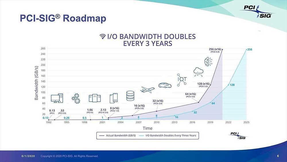
So, for example, if you have a AMD B450 motherboard you’re limited to PCIe 3.0. Furthermore, AMD’s latest budget processors such as the Ryzen 5 5600G are limited to PCIe 3.0, regardless of the motherboard used. In other words, anyone who has purchased a budget CPU to date, with the exception of the new Alder Lake parts, will be limited to PCI Express 3.0.
Now, you could argue that in games like F1 2021 and Resident Evil Village where we kept VRAM usage well under 4GB, that the 4GB 5500 XT was just fine, even with PCIe 3.0 x4 bandwidth. It’s true under those conditions the performance hit should be little to nothing, but the problem is ensuring that VRAM usage is well below 4 GB in current titles is going to be difficult, and in many instances not even possible.
Even if you’re in the know and can monitor this stuff, unless you’re aiming for 3GB or less, it’s hard to know just how close to the edge you are, unless you have an 8GB graphics card on hand to test that.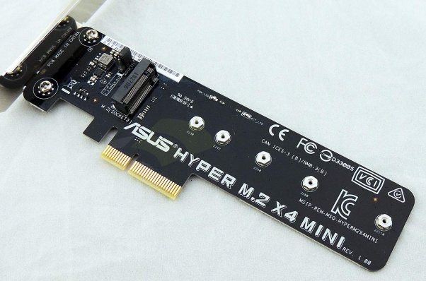 And this is the problem, the 4GB 5500 XT was always right on a knife edge and often went too far. With the full PCIe 4.0 x8 bandwidth, it usually got away without too much of a performance hit, but with PCIe 3.0 x4 it almost always ran into trouble, and in extreme cases wasn’t able to manage playable performance.
But this isn’t about the extreme cases, where we dropped to unplayable performance, it’s about the card being noticeably slower when using PCIe 3.0 x4 bandwidth. In the case of the 5500 XT, we went from 82 fps on average at 1080p in the 12 games tested to just 57 fps, that’s a huge 30% decline in performance.
What’s more crazy is that when using the full PCIe 4.0 x8 bandwidth, the 4GB 5500 XT was 26% faster than the 4GB RX 570, but when limited to PCIe 3.0 x4 it ended up slower than the old RX 570 by a 12% margin. So we’ll say that again, the 5500 XT was 12% slower than the RX 570 when both are using PCI Express 3.0, but the 5500 XT was limited to 4 lanes whereas the 570 used all 16.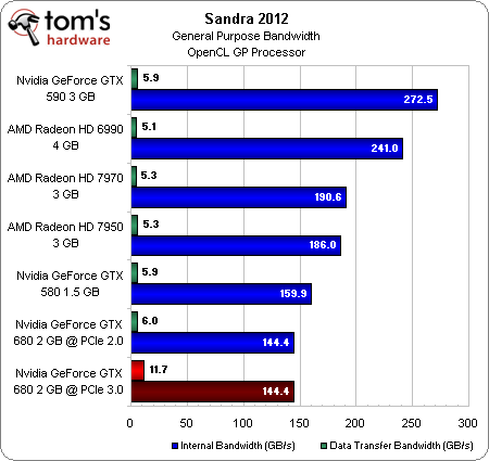
The Radeon RX 6500 XT is likely to face the same problem, but as we mentioned in the introduction, it’s based on a different architecture, so maybe that will help. But if we see no change in behavior, the 6500 XT is going to end up being a disaster for PCIe 3.0 users and at best a mixed bag using PCIe 4.0. One thing is for sure, we’ll be testing all games with both PCIe 4.0 and 3.0 with the 6500 XT, and we’ll be using the same quality settings shown in this review.
That’s going to do it for this one. Hope you enjoyed this PCI Express performance investigation and don’t miss our RX 6500 XT review in the coming days.
Shopping Shortcuts:
- GeForce RTX 3070 Ti on Amazon
- GeForce RTX 3080 on Amazon
- Radeon RX 6800 on Amazon
- Radeon RX 6600 XT on Amazon
- GeForce RTX 3060 on Amazon
- Intel Core i5-12600K on Amazon
- Intel Core i7-12700K on Amazon
- AMD Ryzen 7 5800X on Amazon
Bandwidth Considerations for PCI Express 3.
 0 Designs
By Rita Horner, Technical Marketing Manager, PCI Express PHY IP
PCI Express (PCIe) is a well-accepted standard that is adopted across multiple markets. It is utilized in client servers, storage devices, and now more and more in switches and routers, for chip-to-chip, board-to-board, or even chassis-to-chassis interconnects. Due to PCIe’s multi-channel support and its capability to achieve higher bandwidth through aggregated solution, PCIe has become a big player across multiple market segments.
It is critical for PCIe designers to understand the challenges of meeting the industry’s increased demand in bandwidth that is resulting into higher data rates and higher densities. PCI Express 3.0 standard increased the supported data rate to 8 Gbps, which effectively doubled the previously supported 5 Gbps data rate. While the data rate was increased, no improvements were imposed on the channel, even though the channel experiences significantly more loss at 8 Gbps than at 5 Gbps.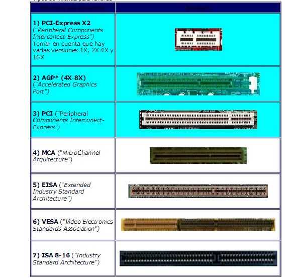 This was mainly done for ease of adoption, backward compatibility and to achieve high volume manufacturability.
To compensate for increased channel loss, PCIe 3.0 specification requires enhanced equalization in the PHY (Physical Layer). PCIe designers must better understand the channel bandwidth limiters so that they can effectively implement sufficient equalization in their next generation designs.
This article dives into the challenges of meeting increasing demands in bandwidth as well as the physical limitations that can constrict bandwidth. Understanding this issue, and why improved levels of equalization are necessary at higher data rates, will enable designers to implement more efficient PCIe 3.0 systems.
Data-intensive applications driving demand for network bandwidth
The increase in demand for higher bandwidth is due to the ever-growing number of users, user devices, and systems being deployed every day. PCI Express has done a great job in keeping up with this increased bandwidth demand by defining a faster data rate every three to four years. But designing at higher data rates, especially at 8 Gbps can be quite challenging. This is due to bandwidth limiters, such as printed circuit board (PCB) traces, connectors and even the IC packages.
According to Cisco’s Visual Networking Index Forecast, global IP traffic has increased eight folds over the past five years, and will increase four folds by 2016, which implies a compound annual growth rate of 29%. Overall IP traffic is expected to grow to 110 exabytes (EB) per month by 2016. (An exabyte is 1018—one million terabytes.) The increase in IP traffic is due to the growth of a wide range of data intensive applications, such as video, voice, network storage, and even distances learning.
Figure 1: Number of networked devices will be double the size of the entire global population
This bandwidth growth is not limited to the high-end networking market, but all across the networking infrastructure, including consumer and business applications. Eighty-eight percent of the 2016 traffic is expected to be due to consumer traffic—which typically means internet video traffic. Internet video streaming and downloads continue to take a large share of the bandwidth, and in fact comprises half of all consumer internet traffic. Greater bandwidth demands translate into demand for higher data rates, higher performance, and higher densities across the entire network infrastructure. Higher speed and greater densities will enable designers to achieve higher bandwidth.
Network infrastructure bandwidth
Higher data rate standards are being adopted across the entire network infrastructure, from the client level (at the bottom of Figure 2) to the core backbone layers of the network infrastructure. Higher data rates are not just for interconnecting high-end systems to systems, or boxes to boxes, but all the way down to line cards and interconnects that are across the access layers, effectively touching the consumer application space.
Figure 2: Increased bandwidth across the entire network infrastructure
The clients, servers, and switches on the bottom of the figure 2, running at 1 Gigabit Ethernet (GE) today, feed the 10 GE, 40 GE, and 100 GE systems that connect to the core. Right now, the growth for 1 GE port adoption rate has started on its downward ramp as 10 GE is growing quickly. Dell’Oro Group forecasted the 10GE port shipments to grow at a rate of almost 50% CAGR in the next five years. As clients, servers, and switches migrate from 1 GE to 10 GE, their respective higher level network infrastructures will also migrate to higher data rates to meet the increased bandwidth demand.
PCI Express is used for almost everything that connects to the access layer, as shown in Figure 2. In storage, servers or switches, almost every application has a PCIe interface, either through the host bus adapter card, LAN on Motherboard (LOM) or a network interface card (NIC).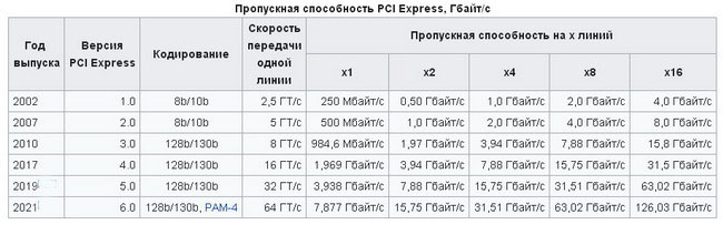
PCI Express bandwidth doubling with each generation
As shown in Table 1, the PCI Express specification is keeping pace with the industry’s increasing bandwidth demands.
From PCIe 1.x at 2.5 Gbps, the specification doubled to PCIe 2.x at 5 Gbps, which enabled speeds of 500 MBps per lane in each direction. PCIe 2.x’s 16-lane connection offered a transfer speed of 16 GBps. PCIe 3.0 doubles PCIe 2.x’s transfer rate, enabling a data rate of 1 GBps per lane, or 32 GBps in a 16-lane configuration. Due to the industry’s insatiable demand for the higher bandwidth, PCI-SIG announced the beginning of the PCIe 4.0 spec in November 2011. PCIe 4.0 is slated to offer 16 GTps (gigatransfers per second) and is targeted to be released in late 2014 to early 2015.
Table 1: PCIe bandwidth doubling every 3 to 4 years
Bandwidth limiters at high PCI Express data rates
Copper loss increases with signal frequency, as shown in Figure 3. Higher data rates increase power loss that translates into decrease in transmission distances. Even moderate printed circuit board (PCB) trace length on the same PCB material will have increased insertion loss at higher frequencies and create signal integrity (SI) problems. These SI issues include amplitude and phase distortion and inter-symbol interference (ISI), which close the eye of a signal.
Figure 3: PCB trace response: copper loss vs. signal frequency
Bandwidth limiters on PCBs
Most traces on a PCB are not isolated signals and have neighboring signals. Therefore, an originally clean signal may be distorted due to cross talk from adjacent signals. Crosstalk is linearly dependent on the length of the trace running in parallel to its neighboring crosstalk aggressor. Even at a relatively low speed of 2.5 Gbps, crosstalk begins causing some distortion (Figure 4), and as data rate is increased to 5 Gbps the crosstalk impact on the signal increases.
Figure 4: Crosstalk effects at 2.5 and 5.0 Gbps
As shown in Figure 5, differential crosstalk can be reduced by increasing the aggressor distance—the distance between the two traces (Figure 6).
Figure 5: Increasing the aggressor distance reduces crosstalk
Figure 6: Aggressor distance: The distance between the differential pair and the aggressor
While crosstalk is a limiting factor, it is manageable, to a point. The cost is in increasing the aggressor distance, but that greater distance means a larger trace area, lower signal density; and not every design may be able to afford its increased cost.
Crosstalk in a backplane environment
A backplane environment is a more complex system, shown in Figure 7. The complete channel starts with a line card trace from where the transmitting signal may be launched, attached to an edge connector, leading to the backplane trace, through a second edge connector, and ending with another line card trace, where the receiving integrated circuit (IC) may reside. The backplane channel has additional bandwidth limiters beyond just the PC board traces. These limiters include the IC package vias due to IC package connections to the line card, PC line cards, backplane board-to-connector vias, and backplane connectors, each of which can cause dispersion, crosstalk, or reflection. At the channel input, or the output of the transmitting IC (TX), the eye is wide open. But as the signal propagates through the channel, it experiences dispersion through the PCB traces, resulting in loss and a signal output eye that may effectively be closed.
Another limiter is the crosstalk caused by adjacent signals on the PCB traces, within the connector pins, or IC packages. It is important to maintain proper differential impedance through connectors. Crosstalk and frequency dependent losses cause signal integrity issues such as ISI. In addition, via stubs’ reflection, signal amplitude distortion, and dispersion can increase ISI.
Figure 7: Complex backplane environment includes multiple potential crosstalk locations
Figure 8 walks through the common locations of signal reflection and dispersion in a backplane.
- The fast edge rate of the initial signal launch on the line card can trigger the first spike on the reflected pulses’ plot, even with minor impedance discontinuities on the PCB. This is as the result of package loss and reflection due to package to PCB via.
- As the signal is launched into the backplane connector at the edge of the first line card, due to the noticeable losses from the line card PCB trace and the line card to connector via, it triggers a second spike on the reflected pulses.
- As the signal travels to the other side of the first backplane connector on to the backplane board, a second spike occurs due to the connector to backplane via reflection.
- The signal then travels across the backplane. Dispersion causes significant losses due backplane PCB trace.
- As the signal enters the second backplane connector on the second end of the backplane, two more reflected pulses occur due to the reflection caused by the backplane to connector via and connector to line card via.
 These two pulses are not as big as the earlier two pulses, due to the two via reflections, as the signal edges are no longer as fast as they were originally at the initial launch.
Figure 8: Common locations of backplane signal reflection and dispersion
PCI Express 3.0 standard enhancements address bandwidth limiters
PCI Express is a widely adopted standard that can take advantage of low-cost PCB materials and connectors. While the bandwidth limitations discussed thus far can be mitigated through the use of lower loss PCB materials and connectors, these may all be cost-prohibitive for certain applications.
The PCIe 3.0 standard definition strived to address these bandwidth limiters, without requiring high-end connectors or exotic PCB materials that would improve the overall channel performance.
Utilizing 128b/130b encoding with data scrambling for DC balance vs. the 8b/10b encoding that was used in the previous two generations enables more efficient signaling with very small overhead compared to 8b/10b encoding.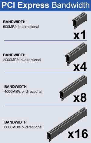 The 128b/130b encoding allows designs to achieve a 10 Gbps data rate equivalent with 8b/10b encoding, and minimizing frequency dependent channel losses.
The PCI Express standard has added enhancements to the transceiver (transmitter and receiver) equalization requirement, with an equalization training algorithm and the need for equalization adaptability. These enhancements enable PCI Express 3.0 adoption while minimizing the impact on the budget of the material cost.
Conclusion
The continual increase in bandwidth demands has created challenges for bandwidth and signal integrity. While the PCI Express 3.0 standard offers some enhancements, designers will require their PHY performance to meet and exceed the base specification while maintaining interoperability across different channels.
The multi-channel DesignWare PHY IP for PCI Express 3.0 includes Synopsys’ high-speed, high-performance transceiver to meet today’s applications’ demands for higher bandwidth.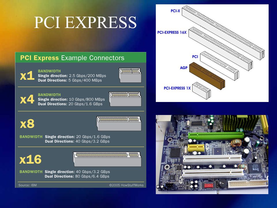 The PHY provides a cost-effective and low-power solution that is designed to meet the needs of today’s PCIe designs while being extremely low in power and area.
Using leading-edge design, analysis, simulation, and measurement techniques, Synopsys’ PCI Express 3.0 PHY IP delivers exceptional signal integrity and jitter performance that exceeds the PCI Express standard’s electrical specifications. The PHY IP reduces both product development cycles and the need for costly field support by employing internal test features. The multi-tap transmitter and receiver equalizers, along with the advanced built-in diagnostics and ATE test vectors, enable customers to control, monitor and test for signal integrity without the need for expensive test equipment.
As the leading provider of PCI Express IP, Synopsys offers a complete PCI Express 3.0 IP solution, including digital controllers, PCIe 3.0 PHY, and verification IP from a single vendor. Accessing all the IP from one provider allows designers to lower the risk and cost of integrating the 8. 0 Gbps PCI Express interface into their high performance SoC designs.
Events
Demo: Visidon DMS on ARC EV7x
Sensor Cortek AI-based radar detection on ARC VPX5
The Ethernet Evolution
PODCASTS
From Data Centers to Devices – The Ongoing [R]Evolution of AI Computing
Newsletters
Technical Bulletin: Latest IP Info on Automotive, Data Center, Security, Processors, PCIe and UCIe.
How many do you need for your workload?
When choosing the motherboard and processor for a PC build, a feature we see most builders often overlook is picking the right amount of PCIe lanes.
Identifying them is not only crucial for a new build but also reduces the need for upgrades down the road, keeping your rig futureproof.
While the first thing that comes to mind when you think about PCIe may be the slot on the motherboard where you connect your graphics card, the underlying, invisible technology is much more extensive.
The PCIe lanes allotted to a component can profoundly impact tasks like rendering with multiple GPUs since the bandwidth of these lanes limits the maximum performance of a component connected to a PCIe slot you can achieve.
In this guide, we will take you through the different types of PCIe configurations and generations you may encounter and help you identify the number of PCIe lanes you require based on your workload.
What is PCIe?
PCIe or Peripheral Component Interconnect Express is a type of interface that allows high-speed components like graphics cards, SSDs, and WiFi cards to connect to your computer.
Typical PCIe connectors take the form of expansion slots on the motherboard, allowing you to physically attach a supported device.
A typical PCIe x16 Slot – Image-Credit: MSI, Unify x570 Motherboard
PCIe lanes explained
PCIe lanes are the physical link between the PCIe-supported device and the processor/chipset.
PCIe lanes consist of two pairs of copper wires, typically known as traces, that run through the motherboard PCB, connecting the PCIe-enabled device to either the processor or motherboard chipset.
You can think of a single PCIe lane as a highway where the vehicles (data here) travel in both directions (to and fro) simultaneously.
Up to 32 of these bidirectional PCIe lanes can be allotted to a single device, enabling it to achieve a high-bandwidth, low-latency transfer of data.
x1, x4, x8, and x16 PCIe configurations explained
As a standard, every PCIe connection features 1, 4, 8, 16, or 32 lanes for data transfer, though consumer systems lack 32 lane support. As one would expect, the bandwidth will increase linearly with the number of PCIe lanes.
Most graphics cards in the market today require at least 8 PCIe lanes to operate at their maximum performance in gaming and rendering applications.
While graphics cards are compatible with being run on less than eight PCIe lanes, you should expect a drop in performance.
In multi-GPU configurations, eight lanes are recommended per GPU, but you could do with fewer lanes depending on your workload.
Features like Nvidia’s NVLink help reduce the load on the PCIe bus and allow you to stack your VRAM across multiple GPUs, but with consumer cards dropping support for the feature, it is best to invest in a system with sufficient PCIe lanes for multiple GPUs without having to rely on NVLink to be supported.
All PCIe slots are not the same
The physical size of the PCIe connector on the motherboard denotes its configuration.
The typical PCIe slots are x1, x4, x8, and x16. To make it easier to differentiate between the physical slots and lanes, we will term them as mechanical and electrical, respectively.
In an ideal scenario, you can assume that the number in the connector’s specification indicates the number of PCIe lanes it carries, but it is not always the case.
The number of PCIe lanes allocated to a particular device or slot on the motherboard varies, and the manufacturer is usually responsible for setting the number of lanes.
Take, for example, the PCIe x16 slots for graphics cards on a motherboard. It’s easy to assume that a mechanical x16 slot makes use of 16 PCIe lanes, but depending on factors like your processor, motherboard chipset, and number of GPUs, the number is subject to change.
Image-Source: ASUS
Take a look at the X570 ROG Crosshair VIII Hero above. The top two mechanical PCIe x16 slots are intended for use with graphics cards.
However, the mechanical x16 slot at the top is the only slot with 16 physical PCIe lanes, which you can make out by zooming into the image.
The middle mechanical x16 slot has eight PCIe lanes, while the bottom one has four.
Even though the slot has a mechanical length of a x16 slot, the pins only reach up to x8 length.
Furthermore, running two GPUs with this motherboard will force the top slot to operate with just eight lanes due to the processor’s limitations, although there are 16 physical PCIe lanes attached to it.
Since the motherboard uses PCIe Gen 4, there is little to no impact on the GPU performance between 8 and 16 lanes, provided the GPU comes with PCIe 4. 0 support. Even PCIe Gen 3 graphics cards will do just fine.
However, with older PCIe generations and motherboards, the performance impact will be significant.
| Processor | Processor family | PCIe lanes | Chipset | Chipset Lanes |
|---|---|---|---|---|
| Intel Core | Intel Rocket Lake | 20 PCIe 4.0 lanes | Z590 | 24 PCIe 3.0 lanes |
| 20 PCIe 4.0 lanes
(motherboard support required) |
Z490 | 24 PCIe 3.0 lanes | ||
| Intel Comet Lake | 16 PCIe 3.0 lanes | Z490 | 24 PCIe 3.0 lanes | |
| AMD Ryzen | Zen 3 and Zen 2 | 20 PCIe 4.0 lanes | X570 | 16 PCIe 4.0 lanes |
| 20 PCIe 4.0 lanes | B550 | 10 PCIe 3.0 lanes | ||
| Zen 2 | 20 PCIe 4.0 lanes | X470 | 8 PCIe 4.0 lanes | |
| 20 PCIe 4.0 lanes | B450 | 6 PCIe 2.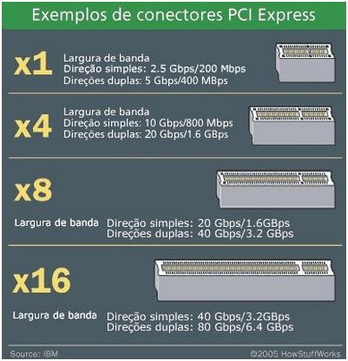 0 lanes 0 lanes |
||
| AMD Threadripper | Zen 2 | 56 PCIe 4.0 lanes | TRX 40 | 16 PCIe 4.0 lanes |
| Zen + | 56 PCIe 3.0 lanes | X399 | 16 PCIe 3.0 lanes | |
| Zen | 56 PCIe 3.0 lanes | X399 | 16 PCIe 3.0 lanes | |
| Intel X | Cascade Lake | 48 PCIe 3.0 lanes | X299 | 24 PCIe 3.0 lanes |
| Skylake | 44 PCIe 3.0 lanes | X299 | 24 PCIe 3.0 lanes |
The above table shows you how many PCIe Lanes modern CPUs support. This is a good start, but you still need to check how Motherboard splits up the available PCIe Lanes onto different connectors on the motherboard.
Chipset vs. processor allocated PCIe lanes
The PCIe lanes on a motherboard originate either from the processor itself or the motherboard chipset.
Generally, the processor lanes are reserved exclusively for the graphics card x16 slots and M.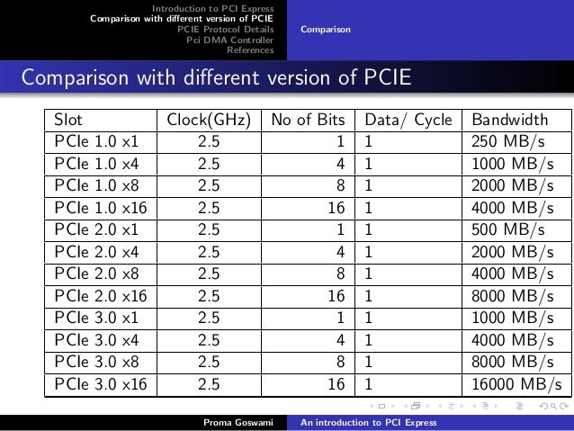 2 slots for high-speed SSDs, as they require to move data without being bottlenecked by the chipset.
On the other hand, chipset lanes connect to onboard USB, other M.2 and PCIe slots, and SATA. The chipset itself transfers data to the processor via a dedicated 4-lane PCIe bus.
So, all devices connected via PCIe lanes to the chipset will have a cap on their maximum bandwidth leading to bottlenecks.
While choosing a motherboard, you must ensure that the PCIe slots you plan to use are directly connected to the processor. You can run a PCIe slot wired to the chipset, but you will risk running into bottlenecks.
A sure way to identify your physical PCIe x16 slot connection would be to identify the lanes allocated to it, as 16 or 8 lanes will directly link with the processor. The topmost PCIe-Slot is almost always connected to the CPU, but do consult your Motherboard manual to make sure this is correct.
PCIe requirements for graphics cards
You might wonder if running your graphics card on the recommended number of PCIe lanes is necessary for the best performance.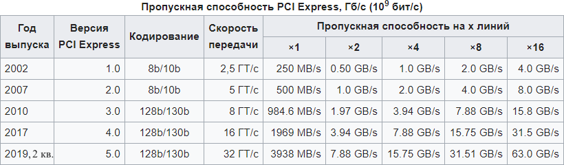
The exact answer to that question lies with the type of work you do, the type of GPU you want to use, and the number of GPUs you plan on using with your rig.
Image-Source: Pugetsystems
Image-Source: Pugetsystems
Even for rendering tasks that take up a large amount of bandwidth, a single current-generation GPU like the RTX 3080 can perform pretty much the same when running on either 8 or 16 PCIe Gen 3.0/4.0 lanes.
If a PCIe-connected device like a graphics card operates near the maximum bandwidth supplied by the PCIe lanes provided to it, the PCIe lanes are said to be saturated.
Depending upon the generation and number of PCIe lanes supplied, bandwidth saturation would vary between PCIe connections.
| PCIe Bandwith | Transfer Rate | Bandwidth x1 (per lane) | x4 | x8 | x16 |
|---|---|---|---|---|---|
| PCIe 1.0 | 2.5GT/s | 250 MB/s | 1.00 GB/s | 2.00 GB/s | 4.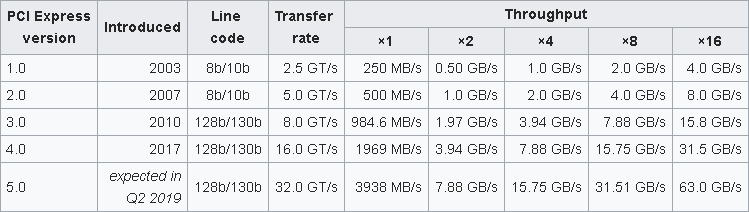 00 GB/s 00 GB/s |
| PCIe 2.0 | 5GT/s | 500 MB/s | 2.00 GB/s | 4.00 GB/s | 8.00 GB/s |
| PCIe 3.0 | 8GT/s | 984.6 MB/s | 3.94 GB/s | 7.88 GB/s | 15.75 GB/s |
| PCIe 4.0 | 16GT/s | 1969 MB/s | 7.88 GB/s | 15.75 GB/s | 31.51 GB/s |
For multi-GPU setups running each GPU on eight lanes would yield the ideal performance.
If you can take a slight drop in performance, running the cards in four lanes is possible but not recommended. You can refer to the table below to better understand the bandwidth requirements of popular graphics cards and decide how many PCIe lanes you would want to allocate.
The following table shows the minimum number and generation of PCIe Lanes popular GPUs require to not be bottlenecked by the PCIe Bandwidth:
| GPU | Required PCIe Gen. & Lane Count for < 1% performance loss |
Required PCIe Gen.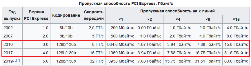 & Lane Count & Lane Countfor < 5% performance loss |
|---|---|---|
| GTX 1660 Super | PCIe 3.0 x4 | PCIe 3.0 x4 |
| RTX 2060 Super | PCIe 3.0 x8 | PCIe 3.0 x4 |
| RTX 2080 Ti | PCIe 3.0 x16 | PCIe 3.0 x8 |
| RTX 3060 Ti | PCIe 4.0 x8 | PCIe 4.0 x4 |
| RTX 3080 | PCIe 4.0 x8 | PCIe 4.0 x4 |
| RTX 3090 | PCIe 4.0 x16 | PCIe 4.0 x8 |
Notes on the above table:
PCIe Lane Scaling will heavily depend on the type of workloads you are running.
If you are rendering simple 3D Scenes or playing Games that easily fit into your GPU’s VRAM, and they need little to no communication over the PCIe bus, you’ll likely see almost no bottlenecking, even when using fewer PCIe Lanes than above recommended.
For tasks that require constant communication with the CPU or access to the system’s Memory, bottlenecking will be much more pronounced.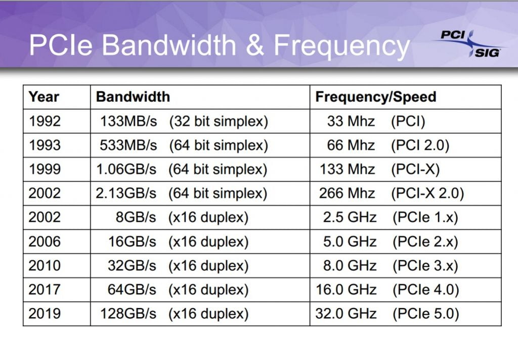
Also note, that PCIe Lanes can only be halved. Even though the RTX 3090 might run without bottlenecking (<1%) at just above PCIe 4 x8 (e.g. PCIe 4 x9), you can’t use x9 PCIe Lanes. You have to double your Lanes and Generation every time.
PCIe Generations: All lanes are not equal
The PCIe standard has gone through a total of six revisions from its inception in 2003.
While the fifth and sixth PCIe generations have not yet made it to the market, PCIe 4.0 and 3.0 are what you would come across today when shopping for a new PC.
Each PCIe generation to date doubled the transfer rate (typically denoted in GT/s) of the previous generation, paving the way for faster devices to connect to computers easily.
PCIe Bandwidth doubles every 3 years – Credit: PCI SIG
Each newer generation also reduced latency, which was necessary for devices like graphics cards.
| PCIe Bandwith | Transfer Rate | Bandwidth x1 (per lane) | x4 | x8 | x16 |
|---|---|---|---|---|---|
PCIe 1.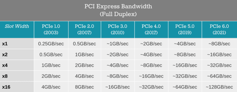 0 0 |
2.5GT/s | 250 MB/s | 1.00 GB/s | 2.00 GB/s | 4.00 GB/s |
| PCIe 2.0 | 5GT/s | 500 MB/s | 2.00 GB/s | 4.00 GB/s | 8.00 GB/s |
| PCIe 3.0 | 8GT/s | 984.6 MB/s | 3.94 GB/s | 7.88 GB/s | 15.75 GB/s |
| PCIe 4.0 | 16GT/s | 1969 MB/s | 7.88 GB/s | 15.75 GB/s | 31.51 GB/s |
PCIe 4.0 vs. 3.0: Double the bandwidth
PCIe 4.0, launched in 2017, was only adopted by the consumer market in 2019, with the third generation of AMD Ryzen processors being the first to support the PCIe generation.
With PCIe 4.0 offering double the bandwidth than the previous generation, it helped improve the performance of components like SSDs, which were developed enough to be bottlenecked by PCIe 3.0.
Not all GPUs make use of increased PCIe Bandwidth as this Benchmarks from Gamersnexus shows
However, even the most powerful graphics cards available today find it difficult to saturate the full PCIe 4. 0 x16 bandwidth and have a similar performance with the previous PCIe 3.0 generation.
So even if the mechanical x16 slot on your motherboard provides just 8 Gen 4 PCIe lanes, you can be assured that the performance would not take a hit.
Multi-GPU setups would greatly benefit from PCIe 4.0 since you would be able to run two PCIe 4.0 cards off eight or even four lanes until you notice the card’s performance begin to drop, allowing you to attach more GPUs on a single system.
Remember that you cannot run a PCIe 3.0 GPU at x16 speeds while connected to PCIe Gen 4 x8 as there are only eight physical PCIe lanes.
Performance impact with older generations
While the performance differences between PCIe 4.0 and 3.0 on current-gen GPUs are (still) negligible, running your devices on older PCIe generations can significantly impact the performance.
Although modern motherboards lack previous generation PCIe lanes, those using older models might find some of their PCIe slots wired with Gen 2 or sometimes even Gen 1 slots.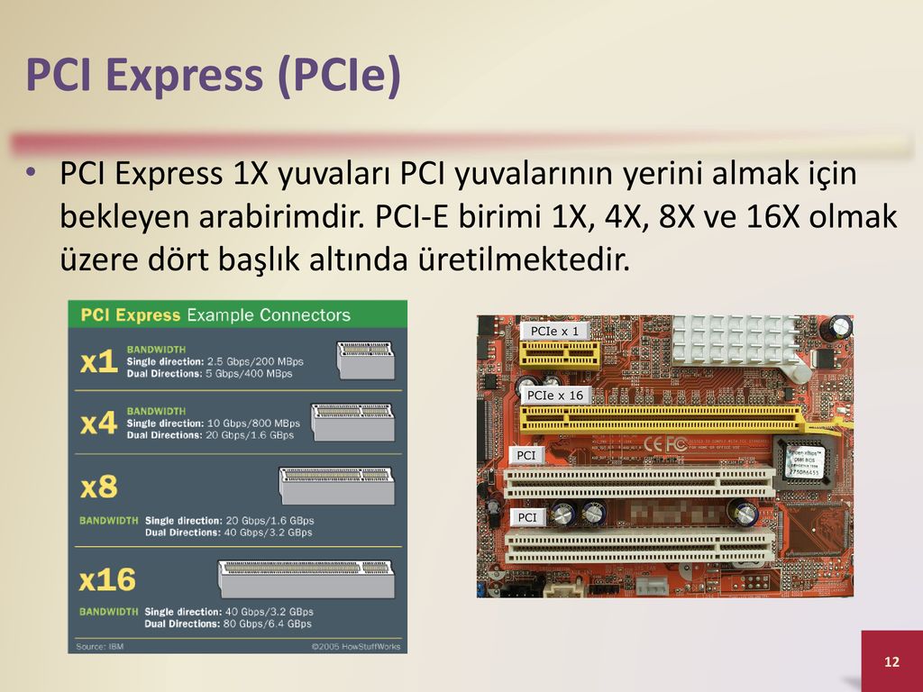
In such cases, modern graphics cards will show significant bottlenecks, with PCIe 2.0 x16 being an exception since it will have a similar performance to PCIe 3.0 x8.
How many PCIe lanes do I need?
The number of PCIe lanes you will need will ultimately depend on the work you plan to do on your PC and the GPU you are using.
We cannot give a universal recommendation as fewer PCIe lanes would throttle your performance, while extra lanes would waste money. We’ve categorized use cases based on the hardware (mainly GPUs and SSDs) required.
Video Editing and Graphic Design
We recommend at least 16 dedicated lanes for the graphics card and four lanes to attach a high-speed NVMe SSD for video editing and graphics design workloads. For additional high-speed storage options and multi-GPU setups, one should consider a HEDT system.
While not demanding in graphics card horsepower, video editing and graphics design can greatly benefit from fast SSDs, networking, and USB connectivity.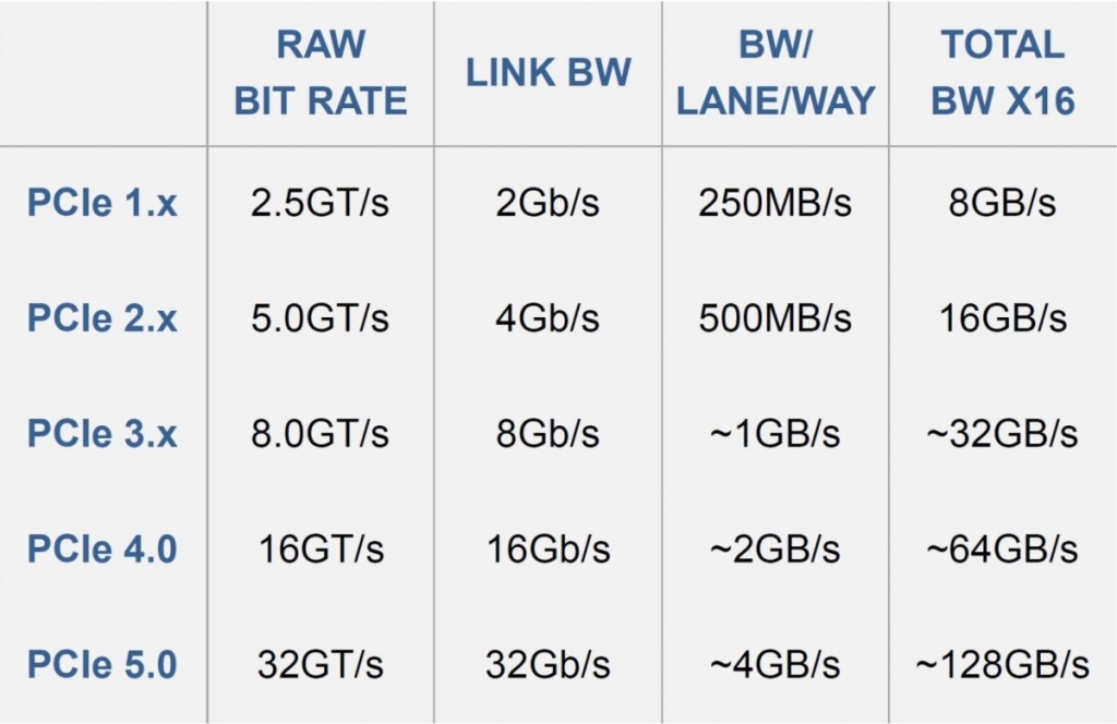
A typical video editing setup would include a single graphics card that takes up a full-sized, mechanical, x16 slot with 16-lanes on the motherboard.
However, as a video editor, access to a large amount of high-speed storage can benefit your workload.
Allocating eight PCIe Gen 3 lanes to an add-on PCIe SSD like the WD Black AN1500 will let you add additional NVMe storage apart from the SSDs that populate the M.2 slots on your motherboard.
Attaching add-on cards could reduce the lanes allocated to your GPU, but the performance impact is minimal, as discussed.
Graphics design would have a similar setup, though you could run SATA SSDs for additional storage to your primary NVMe SSDs.
If you are building a Video Editing PC for Software that can make use of multi-GPU setups, such as Davinci Resolve Studio, or you need more than a single high-performance storage device, consider going with the HEDT Platform such as a Threadripper CPU on a TRX40 Motherboard.
3D Animation and Rendering
We recommend a minimum of 8 PCIe Gen 4 lanes per physical x16 slot on the motherboard for a four-GPU build. You may use fewer GPUs and populate the empty PCIe slots with storage or network cards, depending on your requirements.
3D animation and rendering are some of the most performance-hungry workloads out there, so ensuring you choose the correct amount of PCIe lanes for your 3D Rendering Workstation is essential for maximum performance.
Running multi-GPU setups is often the case here, so providing the support for at least eight lanes of PCIe Gen 3 per GPU will be necessary, though running a Gen 4 setup would be ideal, especially if you do not employ NVLink.
Adding high-speed storage might also require additional lanes depending upon your use case. Apart from populating the M.2 slots on your motherboard, you can employ PCIe slot storage expansion cards for extra high-speed storage if you need it.
Gaming
As a regular gamer, just 16 PCIe Gen 3. 0/4.0 lanes should be enough since most graphics cards will find it difficult to saturate the bandwidth. PCIe 4.0 also beats PCIe 3.0 in latency, so you might see a slight performance gain when gaming with the former.
While gaming might not demand as many PCIe lanes as other, more intensive workloads, features like multi-GPU SLI or Crossfire may require you to invest in a motherboard with more lanes.
Running a stable multi-GPU setup for gaming will need your motherboard to have at least two mechanical PCIe x16 slots, each equipped with a minimum of 16 PCIe 3.0 lanes or 8 PCIe 4.0 lanes each.
Modern cards that support SLI, like the RTX 3090, do not provide enough value to be used in multi-GPU setups for gaming, and with developers leaving out support, the technology almost seems to be dead.
Picking the right amount of PCIe lanes:
Now that you know the required amount of PCIe lanes for your workloads, it is vital to select a capable processor and motherboard.
In this guide, we’ll be taking a brief look at the options available, but you can learn more by visiting our carefully curated guides and reviews below:
- Motherboard Buying Guide for Workstations [How to Buy a Motherboard]
- Intel Core vs. AMD Ryzen CPUs (Benchmarks & Comparison)
- AMD Ryzen Threadripper 3000 Processors (Updated with Launch Details for 3960X and 3970X)
- AMD Ryzen 5000 Series Review for Content Creators – Goodbye Competition
Choosing a processor
We recommend a processor capable of providing at least 16 PCIe 3.0/4.0 lanes for tasks like video editing, graphics design, and general-purpose gaming.
The latest AMD Ryzen 5000-series processors and Intel 11th Gen Core processors can provide a maximum of 16 PCIe 4.0 lanes for graphics cards and storage, making them ideal for such workloads.
For GPU Rendering, the only viable option would be a HEDT (High-End Desktop) processor, like AMD’s Threadripper that comes equipped with up to a total of 62 usable PCIe Gen 4 lanes that attach to GPUs and NVMe storage devices.
Selecting the right motherboard platform
Selecting a suitable processor does not guarantee the availability of the specified number of PCIe lanes. The motherboard is equally essential, especially when taking factors like PCIe 4.0 support and the chipset PCIe link into consideration.
If you plan on using a single graphics card and do not need additional expansion in the future, motherboards like AMD’s B550 and some Intel Z490 boards would be ideal. Keep in mind that although these motherboards have PCIe 4.0 connections to the CPU, the chipset has only a PCIe 3.0 link with the processor.
Some manufacturers will split the 16 PCIe 4.0 lanes between two mechanical x16 connectors for dual GPU support, so if you need to save money, going with these is a great idea.
You can also invest in AMD’s X570 motherboard if you need an extra 4-lane PCIe Gen 4 physical x16 slot. Keep in mind that the lanes would route via the chipset, so using an older graphics card or memory add-on board would be best for this slot.
If you plan on utilizing more than two GPUs, a HEDT processor is the way forward.
HEDT processor supported motherboards like AMD’s TRX40 offer four PCIe 4.0 mechanical x16 slots in the x16/x8/x16/x8 lane configuration and include several high-speed M.2 slots for NVMe storage.
While HEDT platforms offer the required amount of PCIe lanes to run a multi-GPU setup, their high price could put off potential builders on a budget.
In such cases, by choosing consumer motherboards like the Asus WS X570 ACE, which employ a PLX chip, you get access to additional PCIe lanes beyond what the processor can provide.
The PLX chip works by allowing the CPU and RAM to access the address of all connected GPUs. It does this by splitting the processor lanes according to the bandwidth used by each GPU.
So at worse for a dual-GPU setup, it will operate at x8/x8, but when one GPU is actively transferring data, it can allocate the full 16 PCIe lanes to it.
This feature is limited to a few workstation-oriented consumer motherboards but can help cut costs significantly by sticking with a consumer processor and motherboard.
PLX Chips
You’ll find some Motherboards to state they support/offer more PCIe Lanes than should be possible.
The Asus WS X299 Sage for example should only be possible to offer 44 PCIe Lanes, given the CPU has this amount of Lanes available.
In fact, though, that Motherboard offers GPU configs up up to 7x x8 PCIe Lanes (=56), or 4x x16 PCIe Lanes (=64).
This is possible because of a so-called PLX Chip on the Motherboard, which manages PCIe Lanes.
This chip on the one side talks to the CPU and keeps it satisfied telling it there aren’t more PCIe Lanes than the CPU supports being used. The other side though manages a higher amount of PCIe Lanes.
When Using Multi-GPU Setups on a Motherboard with a PLX Switch (ASUS and SuperMicro above), What’s the Performance Loss Exactly?
Well, it depends. A PLX switch limits the simultaneous bandwidth available to GPUs considerably. So, this could mean a good drop in performance if your workload involves throwing things in and out of your graphics cards’ VRAM at a furious pace.
For workloads that can mostly be handled within the GPU VRAM, without too much data movement, you won’t notice that much of a loss of performance.
BIOS settings for optimal operation
Once you finish building your rig, setting up your motherboard for multi-GPU and add-on card support is necessary to ensure a seamless operation.
Sometimes motherboards may not allocate the correct amount of PCIe lanes to your mechanical x16 slot, leading to the GPU not showing up or performing poorly.
Changing the PCIe link speed from automatic to Gen 3 or 4 usually sorts out the issue.
Always make sure to consult your Motherboard Manual if you have problems concerning PCIe Lanes and Slots.
FAQs
Do M.2 drives use PCIe lanes?
Yes, M.2 drives can use up to four PCIe lanes, though the lanes generally route through the chipset. However, it is pretty standard for a single M.2 slot to be connected directly to the processor, and this is the slot where you place your primary NVMe drive.
How many PCIe Lanes does M.2 use?
M.2 Drives typically use x4 PCIe Lanes. This can be 4x PCIe 4.0 Lanes or 4x PCIe 3.0 Lanes, depending on the Motherboard.
What PCIe lanes should I use?
We would recommend going with PCIe lanes connected directly to the processor for your graphics card and primary drive. For other storage drives and add-on cards, using the chipset PCIe lanes is recommended, provided you have fully populated your processor PCIe lanes.
How many PCIe lanes do I have?
First, find out what Motherboard you have. Here’s how you check your Motherboard specs. After you know your Motherboard Model you can check the Motherboard Brand‘s Website for a specs sheet or Manual that’ll let you know how many PCIe lanes you have.
Does it matter which PCIe x16 slot I use?
Yes, choosing the PCIe slot closest to the processor (usually the topmost x16 slot) is recommended as it guarantees a full 16 PCIe lanes are wired to the slot, providing your graphics card with the best bandwidth and lowest latency.
How many PCIe Lanes does a GPU use?
As we discussed in the Article, how many Lanes a GPU uses can differ from how many it needs to run at full performance. Most GPUs use 16 PCIe 3.0 Lanes, while newer GPUs can use 16 PCIe 4.0 Lanes. Most GPUs don’t need that amount though to run without throttling.
What CPU has the most PCIe Lanes?
HEDT and Server-grade CPUs have the highest number of PCIe Lanes. AMD’s Threadripper CPU Series comes with 64 PCIe Lanes, their Threadripper Pro and Epyc CPUs come with 128 PCIe Lanes. With Multi-CPU Systems you can even have access to a multiple of that.
Does RAM use PCIe Lanes?
No, System Memory (RAM) is connected directly to the CPU through its own bus and does not use up any PCIe Lanes.
How many PCIe Slots do you need?
How many PCIe Slots you need depends on the amount of Add-In-Cards you’ll be using. Most need just one for their dedicated Graphics Card. Some require a second slot for a second GPU, a Soundcard, a Wifi Card or for add-in Thunderbolt support. Do note that you most likely won’t need physical x16 PCIe Slots for secondary add-in-cards apart from your GPU.
Over to you
That’s about it from us! Let us know of any questions you might have in the comments or our expert Forum!
CGDirector is Reader-supported. When you buy through our links, we may earn an affiliate commission.
What is PCIe 4.0? PCI Express 4 explained
Back to Blog
by Rambus Press Leave a Comment
PCIe 4.0 is the next evolution of the ubiquitous and general purpose PCI Express I/O specification. It’s also known as PCIe Gen 4 and it is the fourth generation of Peripheral Component Interconnect Express (PCI express) expansion bus specifications, which are developed, published, and maintained by the PCI Special Interest Group (PCI-SIG).
In this blog, you’ll learn all about PCI express 4 performance vs PCIe 3.0. More specifically:
1. PCIe 4.0 bandwidth
2. Market applications: Who needs PCIe 4. 0?
3. PCIe 3.0 vs 4.0: Comparison table
4. Complete PCI express 4 subsystem solutions from Rambus
5. Conclusion
Read our primer? Jump to: PCI Express 5 vs. 4: What’s New?
PCIe 4.0 bandwidth
The interconnect performance bandwidth is double that of the PCIe 3.0 specification achieving 16GT/s and compatibility with software and mechanical interfaces is preserved. PCIe 4.0 architecture is compatible with prior generations of PCIe technology.
PCIe 4 speed chart
To enable this evolution, PCI SIG has been working hard to follow a regular cycle that aims to double PCIe bandwidth every 4 years. PCIe is an Open Standard, directed by PCI SIG, a 22-year old group to allow companies to collaborate on the standard development.
Market applications: Who needs PCIe 4.0?
Big Data needs throughput
According to Gary King, Weatherhead University Professor, “The data flow so fast that the total accumulation of the past two years—a zettabyte—dwarfs the prior record of human civilization”. Internet, ubiquitous smartphone usage and increased marketing accelerated the Big Data revolution and the Internet of Things (IoT) will increase the needs for fast and efficient data management environments. More Throughput and Lower Power are necessary to prevent a bottleneck in the emergence of Big Data.
Networking applications
PCI express 4 lane bandwidth (GB/s)
8-lane and 16-lane PCI Express 3.0 have the bandwidth required to handle a 40Gb Ethernet connection. However, using that many lanes raises cost, packaging, and power issues. A higher speed link requiring fewer lanes would be a much better implementation.
Storage Technologies need more Bandwidth
Data stream provided by PCIe 3.0 (8GT/s) is already sees as a speed limitation for SSD bandwidth. (It can be compared with SAS 12G port that delivers a 12 GT/s data stream). PCIe combined with NVMe will dramatically enhance performance to 16 GT/s per lane.
PCIe 3. 0 vs 4.0: Comparison table
PCI express 4 specifications
There are no encoding changes from 3.0 to 4.0. There were only minor updates in term of protocol. Indeed, evolution to 4.0 is mostly targeted to address the PHY interface. This is expected to be the most challenging issue for designers to solve.
There are also minor changes in terms of link-level management. PCIe 4.0 enables a more robust equalization.
In term of performance, with PCIe 4.0, throughput per lane is 16 GT/s. The link is full duplex, which means the data can be sent and received simultaneously à Total Bandwidth: 32GT/s. No other industry protocol can achieve the bandwidth of the PCIe 4.0 technology (Up to 64 Gbytes/s of total bandwidth for a PCIe 4.0 x16). New emerging interfaces such as: Ethernet 40G/100G, InfiniBand, solid-state drives (SSDs) and flash memory are demanding bigger pipes. These figues make PCIe architecture the only technology solution that achieves this level of performance with minimal new software upgrades.
Complete PCI express 4 subsystem solutions from Rambus
The Rambus PCI Express (PCIe) 4.0 SerDes PHY is designed to maximize interface speed in the difficult system environments found in high-performance computing. It is a low-power, area-optimized, silicon-proven IP designed with a system-oriented approach to maximize flexibility and ease integration for our customers.
In August 2021, Rambus completed the acquisition of PLDA. With this acquisition, Rambus expanded its digital controller offerings with complementary CXL 2.0, PCIe 5.0 and PCIe 6.0 controller and switch IP, and gains critical building blocks for its CXL Memory Interconnect Initiative.
Additionally, with PLDA PCIe 4.0 controller core, we offer a complete PCIe 4.0 SerDes subsystem.
Why choose Rambus’ PCIe 4.0 IP ?
For the reliability:
- Besides our own long-term experience, PLDA’s team has additionally 20+ years of experience in design of IP cores for ASIC with specialization in high-speed interface protocols and technologies,a specific focus on PCIe.
More than 5700 customers, with several hundred ASIC tapeouts.
- PCIe 3.0 architecture is already silicon proven in several projects. Proven PCIe 3.0 architecture is preserved to enable easy migration to PCIe 4.0. No interface change is necessary; existing behavior is preserved for seamless integration.
- PLDA’s PCIe 4 Controller IP’s currently uses the PIE-8 specification, enabling easy integration with PCS layers from multiple PHY vendors. PLDA actively participates in PIE-8 2.0 specification update.
For the Flexibility:
Flexibility of the supported PIPE Configurations for PCIe 4.0:
• PIPE 16-bit is supported in x1, x2, x4, x8 and x16 with 500MHz PIPE clock at 8Gbps (ASIC)
• PIPE 32-bit is supported in x1, x2, x4, x8 with 500MHz PIPE clock at 16Gbps (ASIC)
• PIPE 64-bit will be supported in x1, x2 and x4 with 250MHz PIPE clock at 16Gbps (ASIC/FPGA)
Flexibility of the core configuration to meet spec evolutions
- For the supported features:
Features already proven in 3. 0, optimized for the targeted markets of PCIe 4.0
- Endpoint, root port, switch, dual-mode shared silicon
- Virtualization-ready with SRIOV and ATS/ARI (networking, datacenter)
- Multi-function
- AER and data integrity mechanism
- Complete power management support: legacy, ASPM L0s/L1, OBFF, L1 PM substate with CLKREQ
- End-end TLP prefixes
- Because it is optimized for PCIe 4.0 challenges
Extension Devices:
- Re-timer devices are expected to become widespread in PCIe 4.0 motherboards and backlanes.
PLDA IP Core supports Extension Device ECN
Multiple Packets Per Clock Cycle:
PCIe 4.0 throughput requires larger data paths than previous generations.
Conclusion
PCIe 4.0 is the latest iteration of PCIe to get a commercial release. The two standards are structurally very similar, with the key difference being the higher transfer rate. It offers double the bandwidth than that of its predecessor, PCIe 3. 0 and has double the throughput of PCIe 3.0. Rambus provides fully integrated “Controller + PHY” subsystem solutions for PCIe 4.0 to our customers, targeting various foundry/process combinations. If you have design challenges to solve in your current project, we’re more than happy to help. Reach out our Sales specialists.
Keep on reading:
- The importance of PCI Express 4.0 in the data center
- Complete Interface Solution for PCIe 5.0 Launched
- PCIe 5.0 SerDes PHY (Product page)
Reader Interactions
Bandwidth in IP-networks: calculation and selection of network equipment To the list of rubrics | To the list of authors | To the list of publications
In today’s IP networks, with the emergence of many new network applications, it becomes increasingly difficult to estimate the required bandwidth: as a rule, you need to know which applications you plan to use, what data transfer protocols they use, and how they will communicate
Ilya Nazarov
System engineer of «INTELCOM line» company
After assessing the required bandwidth on each section of the IP network, you need to decide on the choice of OSI network and link layer technologies. In accordance with the selected technologies, the most suitable models of network equipment are determined. This question is also not easy, since throughput directly depends on the performance of the hardware, and performance, in turn, depends on the software and hardware architecture. Let us consider in more detail the criteria and methods for assessing the throughput of channels and equipment in IP networks.
Capacity estimation criteria
Since the advent of teletraffic theory, many methods have been developed to calculate channel capacities. However, unlike the calculation methods applied to circuit-switched networks, the calculation of the required throughput in packet networks is quite complex and is unlikely to provide accurate results. First of all, this is due to a huge number of factors (especially inherent in modern multiservice networks), which are quite difficult to predict. In IP networks, a common infrastructure is typically shared by multiple applications, each of which may use its own distinct traffic model. Moreover, within one session, the traffic transmitted in the forward direction may differ from the traffic passing in the opposite direction. In addition, calculations are complicated by the fact that the speed of traffic between individual network nodes can change. Therefore, in most cases when building networks, the assessment of throughput is actually determined by the general recommendations of manufacturers, statistical studies and the experience of other organizations.
In order to determine more or less exactly how much bandwidth is required for the network being designed, it is first necessary to know which applications will be used. Further, for each application, it is necessary to analyze how the data transfer will take place during the selected periods of time, which protocols are used for this.
For a simple example, consider the applications of a small corporate network.
Capacity calculation example
Suppose there are 300 work computers and the same number of IP phones on the network. It is planned to use the following services: e-mail, IP-telephony, video surveillance (Fig. 1). For video surveillance, 20 cameras are used, from which video streams are transmitted to the server. Let’s try to estimate what maximum bandwidth is required for all services on the channels between the network core switches and at the junctions with each of the servers.
It should be noted right away that all calculations must be carried out for the time of the greatest network activity of users (in the theory of teletraffic — CNN, busy hours), since usually during such periods the network performance is most important and the resulting delays and failures in the operation of applications due to lack of bandwidth are unacceptable. In organizations, the greatest load on the network may occur, for example, at the end of the reporting period or during the seasonal influx of customers, when the most phone calls are made and most mail messages are sent.
E-mail
Going back to our example, consider the email service. It uses protocols that run on top of TCP, that is, the data transfer rate is constantly adjusted, trying to take up all the available bandwidth. Thus, we will start from the maximum value of the delay in sending a message — suppose 1 second will be enough for the user to be comfortable. Next, you need to estimate the average volume of the message sent. Let’s assume that during the peaks of activity, mail messages will often contain various attachments (copies of invoices, reports, etc.), so for our example, we will take the average message size of 500 kb. And finally, the last parameter that we need to choose is the maximum number of employees who simultaneously send messages. Let’s say that half of the employees simultaneously press the «Send» button in the email client during the rush job. The required maximum throughput for email traffic would then be (500 kb x 150 hosts)/1 s = 75,000 kb/s or 600 Mbps. From this we can immediately conclude that to connect the mail server to the network, you must use a Gigabit Ethernet channel.
In the core of the network, this value will be one of the terms that make up the total required bandwidth.
Telephony and video surveillance
Other applications — telephony and video surveillance — are similar in their streaming structure: both types of traffic are transmitted using the UDP protocol and have a more or less fixed bit rate. The main differences are that for telephony the streams are bidirectional and limited by the call time, for video surveillance the streams are transmitted in one direction and, as a rule, are continuous.
To estimate the required bandwidth for telephony traffic, let’s assume that during the peaks of activity the number of simultaneous connections passing through the gateway can reach 100. When using the G.711 codec in Ethernet networks, the rate of one stream, including headers and service packets, is approximately 100 kbps. Thus, during periods of the highest user activity, the required bandwidth in the network core will be 10 Mbps.
Surveillance traffic is calculated quite simply and accurately. Suppose, in our case, video cameras transmit streams of 4 Mbps each. The required bandwidth will be equal to the sum of the speeds of all video streams: 4 Mbps x 20 cameras = 80 Mbps.
Finally, it remains to sum up the obtained peak values for each of the network services: 600 + 10 + 80 = 690 Mbps. This will be the required bandwidth in the network core. The design should also consider the possibility of scaling so that the communication links can serve the traffic of a growing network for as long as possible. In our example, the use of Gigabit Ethernet will be enough to satisfy the requirements of the services and at the same time be able to seamlessly grow the network by connecting more nodes.
Of course, the given example is far from a reference one — each case must be considered separately. In reality, the network topology can be much more complex (Fig. 2), and throughput needs to be estimated for each of the network sections.
Keep in mind that VoIP traffic (IP telephony) is distributed not only from phones to the server, but also between phones directly. In addition, different departments in an organization may have different network activity: the help desk makes more phone calls, the project department uses e-mail more than others, the engineering department consumes Internet traffic more than others, and so on. As a result, some parts of the network may require more bandwidth than others.
Useful and total bandwidth
In our example, when calculating the IP telephony stream rate, we took into account the codec used and the size of the packet header. This is an important detail to keep in mind. Depending on the encoding method (codecs used), the amount of data transmitted in each packet, and the link layer protocols used, the total bandwidth of the stream is formed. It is the total bandwidth that should be taken into account when estimating the required network bandwidth. This is most relevant for IP telephony and other applications that use low-rate real-time streaming, in which the size of the packet headers is a significant fraction of the packet size. For clarity, let’s compare two VoIP streams (see table). These streams use the same compression, but different payload sizes (the actual digital audio stream) and different link layer protocols.
Pure data transfer rate, excluding network protocol headers (in our case, digital audio stream), is a useful bandwidth. As can be seen from the table, with the same useful throughput of streams, their total throughput can vary greatly. Thus, when calculating the required network bandwidth for telephone calls during peak loads, especially for telecom operators, the choice of channel protocols and flow parameters plays a significant role.
Equipment selection
The choice of link layer protocols is usually not a problem (today the question is more often how much bandwidth an Ethernet link should have), but even an experienced engineer can find it difficult to choose the right equipment.
The development of network technologies along with the growing demands of applications for network bandwidth is forcing manufacturers of network equipment to develop new software and hardware architectures. Often, at a single manufacturer, there are at first glance similar models of equipment, but designed to solve different network problems. Take, for example, Ethernet switches: along with the usual switches used in enterprises, most manufacturers have switches for building storage networks, for organizing operator services, etc. Models of the same price category differ in their architecture, «sharpened» for certain tasks.
In addition to overall performance, the choice of hardware should also be driven by the supported technologies. Depending on the type of equipment, a certain set of functions and types of traffic can be processed at the hardware level, without using CPU and memory resources. In this case, the traffic of other applications will be processed at the software level, which greatly reduces the overall performance and, as a result, the maximum throughput. For example, multilayer switches, due to their sophisticated hardware architecture, are capable of transmitting IP packets without performance degradation when all ports are fully loaded. Moreover, if we want to use more complex encapsulation (GRE, MPLS), then such switches (at least inexpensive models) are unlikely to suit us, since their architecture does not support the corresponding protocols, and at best such encapsulation will occur at the expense of the central processor low performance. Therefore, to solve such problems, one can consider, for example, routers whose architecture is based on a high-performance central processor and depends more on software than hardware implementation. In this case, at the expense of maximum throughput, we get a huge set of supported protocols and technologies that are not supported by switches of the same price category.
Overall hardware throughput
Manufacturers often list two maximum throughputs in their hardware documentation, one in packets per second and the other in bits per second. This is due to the fact that most of the performance of network equipment is usually spent on processing packet headers. Roughly speaking, the equipment must accept the packet, find a suitable switching path for it, form a new header (if necessary) and pass it on. Obviously, in this case, it is not the amount of data transmitted per unit of time that plays a role, but the number of packets.
If two streams are compared at the same rate but with different packet sizes, the stream with the smaller packet size will require more performance. This fact should be taken into account if the network is supposed to use, for example, a large number of IP-telephony streams — the maximum throughput in bits per second will be much less than declared here.
It is clear that with mixed traffic, and even taking into account additional services (NAT, VPN), as it happens in the vast majority of cases, it is very difficult to calculate the load on equipment resources. Often, equipment manufacturers or their partners perform load testing of different models under different conditions and publish the results on the Internet in the form of comparative tables. Familiarization with these results greatly simplifies the task of choosing an appropriate model.
Pitfalls of modular equipment
If the selected network equipment is modular, then, in addition to the flexible configuration and scalability promised by the manufacturer, you can get a lot of «pitfalls».
When selecting modules, carefully read their descriptions or consult the manufacturer. It is not enough to be guided only by the type of interfaces and their number — you also need to familiarize yourself with the architecture of the module itself. It is not uncommon for similar modules when, when transmitting traffic, some are able to process packets autonomously, while others simply forward packets to the central processing unit for further processing (accordingly, for the same external modules, the price for them can vary several times). In the first case, the overall performance of the equipment and, as a result, its maximum throughput are higher than in the second, since the central processor shifts part of its work to the module processors.
In addition, modular equipment often has a blocking architecture (when the maximum throughput is less than the total speed of all ports). This is due to the limited bandwidth of the internal bus through which the modules exchange traffic between themselves. For example, if a modular switch has a 20 Gb/s internal bus, then only 20 ports can be used for its line card with 48 Gigabit Ethernet ports when fully loaded. Such details should also be kept in mind and when choosing equipment, carefully read the documentation.
General recommendations
When designing IP networks, bandwidth is a key parameter that will affect the architecture of the network as a whole. For a more accurate estimate of throughput, you can use the following guidelines:
- Study the applications that you plan to use on the network, the technologies they use, and the volumes of transmitted traffic. Use the advice of developers and the experience of colleagues to take into account all the nuances of these applications when building networks.
- Learn in detail the network protocols and technologies used by these applications.
- Read the documentation carefully when choosing equipment. To have some stock of ready-made solutions, check out the product lines of different manufacturers.
As a result, with the right choice of technologies and equipment, you can be sure that the network will fully meet the requirements of all applications and, being flexible and scalable enough, will last for a long time.
Bandwidth of interfaces
Bandwidth of interfaces
Inquiry on products
Inquiry on products
Please fill in and submit the form and AltaStor managers will contact you shortly.
Thank you for your contact.
AltaStor manager will contact you shortly.
Your request is already being processed.
No need to re-apply.
AltaStor manager will contact you shortly.
You can also refresh the page after 10-15 minutes, correct the request and, if necessary, resend it.
Something went wrong.
We are already aware of the issue and are working on a fix.
Please try again after a while or contact us by phone: +7 495 777-90-29.
Organization name:
Contact person:
Contact phone:
Email:
Preferred contact method:
- By phone
- By email mail
Comment:
I agree:
I accept the terms
User Agreement
and I consent to the processing of my personal data,
in accordance with the Federal Law of July 27, 2006
No. 152-FZ «On Personal Data», on the terms and for the purposes,
certain
Privacy Policy.
The transfer rate of a data interface is the maximum rate at which data can be transferred over a given interface. Do not confuse the bandwidth of an interface with the bandwidth of individual devices that are connected to it. Many interfaces are not capable of transferring data as fast as possible due to their inherent overhead. Some adapters have CPU-less hardware processing capabilities that improve the performance, manageability, and reliability of data transfer across the interface. For the interfaces listed in the table, the throughputs are based on a single port transmission in half-duplex mode.
Coding scheme differences in bits and bytes
Bandwidths for storage systems are usually specified in MB/s. Many interfaces use an 8b/10b encoding scheme that maps 8-bit bytes to 10-bit characters for transmission at the physical layer, with the extra bits used for control. Therefore, for such interfaces, the throughput in MB/s is considered as the throughput in Mb/s divided by 10. The overhead for the 8b/10b encoding scheme is 20% (10-8)/10.
Starting with 10Gb Ethernet and 10Gb Fiber Channel (for ISL), a 64b/66b encoding scheme with improved efficiency is used. Circuit 64b/66b was designed for high throughput FC and InfiniBand. By itself, 64b/66b encoding is not compatible with 8b/10b, but sometimes devices at the hardware level may support the implementation of the old scheme.
16Gb Fiber Channel has a line rate of 14.025Gbps, but with 64b/66b encoding scheme has twice the throughput of 8Gb Fiber Channel which has a line rate of 8.5Gbps. 64b/66b encoding incurs 3% overhead (66-64)/66.
Comparative table of interfaces
| The maximum distance (m) | Type of cable | INTERVION Controller | Transmission speed (MB/S) | Intricate of Interface | FC | 16M
All articles ethernet FCoE fiber channel Infiniband iSCSI PCI Express SAS SATA USB Data interfaces Storage Connection Types PCI Express Connector types Development of data interfaces Comparison of fiber optic and copper cables BlogRecommendations for building enterprise-level video surveillance systems How to save money when buying server hardware Special offersNetApp All Flash FAS at special prices Labeled LTO-6 and LTO-7 Ribbon Cartridges Services Storage selection Server selection Selection of switches RAID Calculator About company Blog Technology Contacts Products Storage systems Server equipment Switching equipment Services Selection of storage systems Server selection Switching selection RAID calculator Special offers Network bandwidth for Azure VM
Azure provides several different types and sizes of virtual machines, each with a specific combination of performance characteristics. The network bandwidth allocated to each virtual machine determines the data transfer rate from the virtual machine (outbound traffic). The limit applies to all network traffic leaving the virtual machine, regardless of its destination. For example, if a VM is capped at 1000 Mbps, that quota is consumed for any outbound traffic, either to another VM in the same virtual network or outside of Azure. Incoming traffic is not measured or directly restricted. However, the VM’s ability to process incoming data may be limited by other factors, such as CPU and/or storage limits. The Network Acceleration feature improves network performance in terms of network latency, bandwidth, and CPU usage. Multiple network interfaces can be attached to an Azure VM, and at least one must be present. The bandwidth allocated to a virtual machine is estimated by the sum of the outgoing traffic on all network interfaces attached to it. In other words, bandwidth is allocated to the virtual machine as a whole, regardless of the number of network interfaces attached to it. To find out how many network interfaces Azure VMs of different sizes support, see VM sizes for Windows and Linux. Expected network bandwidth Expected network bandwidth and the number of supported network interfaces for different VM sizes are listed in the size descriptions for Windows and Linux VMs. Select the type you are interested in, such as «General Purpose», and then on the corresponding page, select a series of sizes, such as Dv2. The bandwidth limit applies to the entire virtual machine. Throughput is independent of the following factors.
Network flow limits In addition to bandwidth, network performance can be affected by the number of network connections on a virtual machine at any given time. Transferring data between endpoints requires the creation of multiple streams in addition to those that carry out this transfer. For example, these could be threads created for DNS resolution or load balancer health probes. Also note that network virtual appliances such as gateways, proxies, and firewalls will see flows that are created for connections completed and initiated by the device. Azure Network Stack currently supports 1M threads per VM (500K in and 500K out). The following is the total number of active connections that the virtual machine can handle under various scenarios.
Once this limit is reached, subsequent connections are dropped. The speed at which a connection is established and terminated can also affect network performance, as it uses the CPU in conjunction with packet processing routines. We recommend benchmarking, comparing workloads against expected traffic patterns, and scaling to suit your needs. Metrics are available in Azure Monitor to track the number of network flows and the rate at which they are created on the VM or VMSS instances. Next steps
What should be the bandwidth of the Internet channel for a live broadcast? | Articles «What data rate do I need to stream live?» is a common question that users contact the Epiphan Video Technical Support Department. So how much bandwidth is needed to provide a seamless live stream? The answer is: it depends on many factors! Only taking into account such parameters as the quality of the video stream, encoding settings, as well as a number of other significant conditions, you can make a really high-quality online broadcast. Bandwidth for streaming video To upload streaming video to the Internet, you need to consider network bandwidth. An example of such outbound downloads could be sending a file via e-mail, storing data in the cloud storage, or posting a live broadcast on the air. Bandwidth usually has certain speed parameters (such as «5 Mbps»), which depend on your ISP. The incoming access speed is usually higher than the outgoing one (for example, 15 Mbps — incoming and 5 Mbps — outgoing). It is important to know exactly the outgoing speed of your network, because it is it that affects the quality of the broadcast audio / video signal. Signal encoding also plays a roleStreaming content requires encoding (or compression). Video content (and, to a lesser extent, audio content) that has not been compressed requires too much bandwidth to maintain an acceptable stream quality. Your content is encoded by a small program called a codec, using either software (such as open source programs like OBS Studio) or hardware (like our Pearl Mini All-In-One). The purpose of encoding is to digitize and compress the audio/video signal, which allows you to adjust the content parameters to the network bandwidth with little or no loss of quality. The audio/video data stream processed per unit of time is called the bit rate. The higher the bitrate, the better the quality of the audio/video signal. But if your bitrate is too high in relation to the upstream access speed, then your broadcast will not be available to viewers. For example, a video stream with a bit rate of 6 Mbps will not work with an outgoing access rate of 5 Mbps. If you want to stream at a non-standard resolution, you may find the recommendations from the popular Netflix resource below useful: What do you need to successfully stream?It’s simple math to calculate that with an upstream access speed of 5 Mbps, the bit rate should also not exceed 5 Mbps. But still, what exactly should it be? Bandwidth limits are only part of the story! You also need to take into account some additional factors to ensure the quality of your broadcast. 1. Always need a small margin Make sure you have some margin up to your network bandwidth limits. This reserve will act as a buffer for your broadcast in case of possible changes in your connection parameters. Use a simple formula to calculate your required network bandwidth: That is, we recommend that you always have about 1.5 times your bitrate in reserve in order to avoid possible connection fluctuations. For example, if your streaming bitrate is 5 Mbps, make sure your bandwidth is at least 7.5 Mbps to maintain a stable and high quality video stream. Of course, you can use our formula and calculate the throughput as accurately as possible, but it’s really always better to have a little more on hand! Please note that our «at least 1.5 times» formula applies to most broadcasts — except for broadcasting video in relatively low quality (less than standard definition). If the overall upstream speed is very low, a 1.5x increase will not make much of a difference in improving the video signal throughput. In this case, we recommend laying an additional margin so that the result justifies itself! 2.
There are many different types of Internet connections, such as DSL, cable, satellite, cellular, and so on. Each connection type has its own parameters for incoming and outgoing access speeds and connection reliability indicators. These data must be taken into account when planning a live broadcast. For example, DSL tends to have slower download speeds, which can limit the outgoing video stream speed and broadcast quality, respectively. What if you live in a rural area and use satellite communications? In this case, you should pay attention to the weather conditions — it may depend on them how successful your broadcast will be. 3. What your ISP really offersMany ISPs use maximum upload and download speeds to advertise their service packages. For example, an advertisement may sound like this: “Outgoing access speed — up to 10 Mbps, incoming — up to 30 Mbps!”. The key word here is «up to» because internet speeds can vary. Some ISPs may also charge you for maximum bandwidth, so make sure you don’t incur additional internet charges when hosting live streams. Not sure how to find out exactly what speed your Internet connection is? Now there are many special applications that allow you to test the actual speed online, such as Google Fiber speed test. 4. Providing enough speed for multi-streaming Multi-streaming, which is broadcasting to several platforms at the same time, is gaining popularity among Internet users. Multi-encoding, on the other hand, is a similar technology that allows you to make simultaneous broadcasts with different bitrates. Multi-streaming allows you to reach more viewers, and multi-encoding allows you to make your broadcast available to users with different bandwidth limits. To sum it upAs you can see, the speed required to upload a live video to the Internet depends on various factors. There are no such general bandwidth parameters that would take into account all the requirements and conditions for all online broadcasts, regardless of the type of connection. Just keep in mind the useful formula «at least 1.5 times» and take into account the bitrate of all currently running programs, and this should help you organize a high-quality uninterrupted broadcast on the Internet. CV consumption calculator | SwagelokSend Use this calculator to select a valve with sufficient capacity for your application. Gas pressure units at absolute pressure other than psi. inch man.
Additional information and resources
Calculation type
Medium type
Inlet pressure (P1) This field is required
pounds per sq. Outlet pressure (P2) This field is required pounds per sq. inchPabarmPalb/sq. inch g Consumption (Q) This field is required std. cube feet per minutestdl/minstdm3/hstdml/mingal/minl/hr/ml/cm3/hr Temperature This field is required ºFahrenheitºCelsiusºKelvin System medium AcetoneEthyl alcoholMethyl alcoholBenzeneGasolineKeroseneSea waterWaterAcetyleneAirAmmoniaArgonButaneCarbon dioxideHeliumHydrogenMethaneNitrogen Volume weight This field is required flow units std. CV: Flow: Please enter temperature data. Please enter pressure data. PRTG Bandwidth Monitoring ToolFree Download
Full version of PRTG for 30 days. After 30 days — free version. Bandwidth monitoringGo directly to the topic of your choice
Bandwidth monitoring for professionals In professional environments (enterprises and large organizations), the impact of reduced bandwidth is quite severe. In this case, our bandwidth monitoring tool will help you monitor bandwidth, identify and evaluate significant bandwidth congestion, quickly detect potential outages — and ultimately determine the cause of the problem. Bandwidth measurement: three situations where PRTG comes in handyPRTG allows you to quickly identify potential causes of bandwidth congestion and isolate the causes of failures. Overloading a single network component can quickly result in a significant drop in throughput. Large file transfer problemsAlmost every company sends large files. Transferring such files consumes a significant amount of bandwidth. But the bottlenecks that go undetected on every network slow down file transfers. Applications running slowly Do your colleagues complain that the programs they use internally are too slow? Are your customers unhappy because your website keeps crashing? In these cases, the problem is probably your bandwidth. Backup failuresNo IT department needs backups. In general, backing up or synchronizing databases requires significant bandwidth. Without sufficient bandwidth, your network capacity can be exhausted. “PRTG makes our work much more comfortable knowing that our systems are continuously monitored”Markus Puke, Network Administrator, Schüchtermann Clinic This is what bandwidth monitoring looks like in PRTG
Sensor for bandwidth monitoring Packet analyzer PRTG Sun PRTG makes your life easier! Our monitoring software works for you PRTG saves time By purchasing PRTG, you get a single centralized tool for monitoring the operation of servers and the entire network. Get the ability to monitor your entire infrastructure with our app and dashboard. PRTG saves your nervesInstalling PRTG is very easy. Getting started with PRTG or switching from another monitoring tool is seamless with auto-discovery and ready-made templates for multiple devices. PRTG saves moneyPRTG is worth the money. 80% of our customers report savings in network management. And the costs of PRTG licenses pay off in just a few weeks on average. Free Download
Full version of PRTG for 30 days. After 30 days — free version. Customer example: Austrian rail system uses PRTG
“The continuous and uninterrupted operation of ÖBB Infrastruktur AG’s data network is of paramount importance for the operation of critical applications. To make this a reality, management decided to install PRTG Network Monitor. The PRTG software is used to monitor the throughput of central routers and switches in the data network, allowing administrators to determine the most important key usage and availability parameters. Application example (in German) Free e-mail course: Still new to monitoring and need support?Paessler offers a free multi-part course distributed by email. The course covers 4 main methods of bandwidth monitoring: SNMP, packet sniffing, Flow and WMI. Get to know the individual processes and how they can be used to improve bandwidth usage on your network. Sign up here for our free email course and learn how to optimize your resource usage with a bandwidth meter. Market leading monitoring solution. We are trusted by over 500,000 users.Trustpilot Free Download
Full version of PRTG for 30 days. After 30 days — free version. Throughput testing: use PRTG to test successfully!
PRTG Bandwidth Monitoring MethodsPosted by Kimberly, Evangelist This video provides a quick overview of the methods available in PRTG for bandwidth monitoring. Watch Video (3:04 Min., English) Would you like to know if your ISP is actually delivering the promised bandwidth? Then you, like many administrators, probably run SLA reviews frequently. But how do you test throughput? There are two difficulties here: Complexity 1: To test the maximum bandwidth of the channel, it must be used with maximum load. This means that during the execution of the test, there will be no resources left to transfer other data. In other words, you paralyze your network. Complexity 2: For 100% measurement confidence, you would essentially need two computers directly at the ends of the link you want to test throughput. Otherwise, you will simultaneously test all network devices found in the tested channel. For these reasons, it is not possible to measure throughput directly during the entire test. Instead, the link speed should be tested by generating short-term peaks, such as downloading a small file (a few kilobytes in size) every few minutes and measuring the time it takes to download. Solution: Here’s how to test throughput with PRTG
for example, static websites of your ISP). Let the sensors run for several hours at 5 minute intervals. Sensors have a channel that indicates the throughput values (in KB/s) reached during file downloads. For example, if you have a data link with a given bandwidth of 4 Mbps, then a test using a 500 KB file should take 1000 ms (1 second): 4 megabits per second = 0.5 MB per second = 500 KB per second If the channel is being used by other users during the test, you will see unwanted fluctuations in the curve because the test is not always performed when all available bandwidth is available. If there was no other traffic in the channel, then the curve will look very much like a straight line. Performing throughput tests with PRTG will allow you to monitor network performance and identify potential bottlenecks. Attention! If you upload a 500 KB file every 60 seconds, then 720 MB of data will be transferred in a day! Bandwidth Monitor: What makes PRTG better than the rest?Quick Troubleshooting Troubleshooting without a monitoring tool can be time consuming and costly. Resource Insufficiency DetectionPRTG allows you to track throughput over time and detect peak times. This allows you to plan ahead to allocate more bandwidth at certain times: for example, when a website is accessed by a large number of visitors, when users typically download many applications, or when a system upgrade is in progress. Quick diagnosis of the load in useIs your bandwidth slowly reaching its limit? Using PRTG, you will immediately know that the maximum bandwidth is being used. This will allow you to plan the deployment of new resources in a timely manner. Reduce costs By identifying and eliminating bandwidth eaters, you improve the efficiency of your network. It also achieves significant cost savings. In most cases, these benefits alone will quickly offset the cost of acquiring PRTG. Improve moraleBy using PRTG to test throughput, you’ll ensure consistent throughput, increase the reliability of your network, and simply gain more control over your IT infrastructure. As a result, you will play a major role in both increasing the productivity of your colleagues and improving customer satisfaction. Free Download
Full version of PRTG for 30 days. After 30 days — free version. PRTG: Revolutionary network monitoring softwareTailor PRTG individually and dynamically to your needs and rely on the robust API :
Practical tip: “Listen Matthias, what would you say to administrators who want to monitor bandwidth? » “Instead of measuring throughput by generating additional load, it is better to look for activities that themselves generate such load and track them. Matthias Hengl, PRTG developer at Paessler AG
Are you still in doubt?
|
|---|
|
PRTG | Network Monitoring Software — Version 22. |