How to Control an Arduino from a Raspberry Pi
The “Should I use a Raspberry Pi, or should I use an Arduino?” question always comes up in the first stages of product development. Honestly, who wouldn’t be confused? Both boards are insanely popular, but there are subtle differences in their optimal use cases.
The Raspberry Pi is a computer, so it uses an operating system. This creates multiple layers of abstraction that make real-time signal generation and detection unreliable. On the other hand, the Arduino can read and write electronic signals much faster and more reliably than the Raspberry Pi.
Luckily the Arduino and Raspberry Pi can be used together in the same project to take advantage of features from each board.
In this tutorial we will learn how to control the Arduino’s GPIO pins with a Python program run by the Raspberry Pi. The Arduino can be connected to the Raspberry Pi directly with a USB cable. To do this we will use a protocol called Firmata.
Firmata
Firmata is a communication protocol that connects a microcontroller to software on a host computer. Think of Firmata as a language that the Raspberry Pi and the Arduino both understand.
Setting Up the Arduino
The easiest way to setup Firmata on the Arduino is by using the Raspberry Pi. First, we need to install the required software.
1. Connect the Raspberry Pi to the internet. Open command terminal and enter the following command:
sudo apt-get -y install arduino python-serial mercurial
2. Now, connect the Arduino to the Raspberry Pi with an A to B USB cable.
3. Open the Arduino IDE, and select the correct port for the device.
4. Next, upload the PyFirmata firmware to the Arduino by opening the sketch from File > Examples > Firmata > Standard Firmata.
5. Finally, click the upload button.
Setting Up the Raspberry Pi
To prepare the Raspberry Pi:
1. First, install the pyFirmata files by entering this:
git clone https://github.com/tino/pyFirmata
2. Then, run the following commands:
cd pyFirmata
sudo python setup.py install
Preparing the Hardware
To demonstrate how Firmata works, we will build a project that uses a Python program on the Raspberry Pi to control the Arduino’s GPIO pins. We will connect a button and LED to the Arduino so that the LED lights up when the button is pressed.
To build this project, we need the following components:
- Raspberry Pi
- Arduino Uno
- Jumper wires
- Breadboard
- Tactile push button
- One LED
- One 220 Ohm resistor
- A to B USB cable
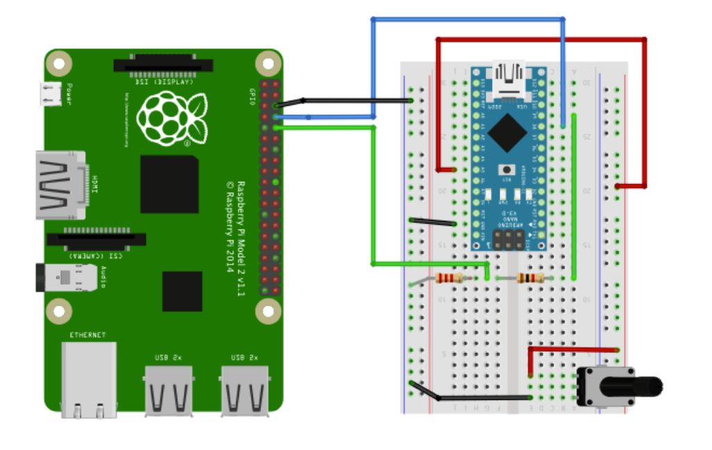
Follow this diagram to connect the LED and push button to the Arduino. The Arduino is connected to the Raspberry Pi with an A to B USB cable:
Figure 1: Hardware connections
To learn more about the Arduino, check out our Ultimate Guide to the Arduino video course. We teach Arduino programming and circuit building techniques that will prepare you to build any project.
Python Code
Copy the code below to your Raspberry Pi and save it as a “.py” file. Run the program by typing python filename.py:
import pyfirmata
led_pin = 7
button_pin = 8
board = pyfirmata.Arduino("/dev/ttyACM0")
while True:
    if board.digital[button_pin].read(1):
        board.digital[led_pin].write(1)
    else:
        board.digital[led_pin].write(0)
Code Explanation
First, we import the pyfirmata library using import pyfirmata. Then we label the LED and button pins by storing them into variables: led_pin and button_pin. To make this program connect to the Arduino, we need to tell it the port where the Arduino is connected. Use pyfirmata.Arduino() and then create the instance by assigning the port in the board variable. In this case it’s /dev/ttyACM0.
The while loop basically acts like void setup(). We use an if statement to monitor the status of the button. If the button sends a HIGH signal, meaning it was pressed, the LED lights up. Both use the
 digital[].read and digital[].write methods to control the GPIO pins on the Arduino.
Now when you press the button the LED should light up. Press CTRL + C to stop the program.
Hope this tutorial has helped you to understand how to control the Arduino with a Raspberry Pi. Leave a comment below if you have any questions!
Programming an Arduino from Raspberry Pi
Problem
You want to run the Arduino IDE on a Raspberry Pi so that you can write and upload programs onto an Arduino.
Solution
The Arduino IDE is available for the Raspberry Pi. It is a little bit slow, but usable. Use these commands to install it:
$ sudo apt-get update
$ sudo apt-get install arduino
At the time of writing, this installs version 1.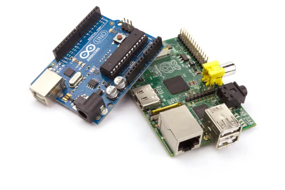 0.1, which is not the latest version but will suit the Arduino Uno; it will not, however, work for newer boards like the Leonardo and Due. They can still be used with the Raspberry Pi, but you will need some other computer to program them before connecting them to the Raspberry Pi.
After installation, you will find an Electronics group in your Programs menu (Figure 10-1).
Figure 10-1. The Arduino IDE running on Raspberry Pi
The Arduino IDE connects to the Raspberry Pi through its USB cable to program it. This connection also requires that the serial console be disabled. You can follow “Freeing the Serial Port” to do this, but a second option is to run a script created by Kevin Osborn that both disables the serial console and configures the serial ports and Arduino profiles necessary to get things running. This has the advantage that it also sets up the aLaMode board to be ready for use (“Getting Started with an aLaMode Board and a Raspberry Pi”).
To download and run this script, follow these steps:
$ wget https://github.com/wyolum/alamode/blob/master/bundles /alamode-setup.tar.gz?raw=true -O alamode-setup.tar.gz $ tar -xvzf alamode-setup.tar.gz $ cd alamode-setup $ sudo ./setup
If you have not previously disabled your serial console and are relying on the preceding script to do it, then you will need to reboot for this change to take effect.
$ sudo reboot
You can now connect your Arduino to your Raspberry Pi. From the Tools menu, select Board and set the board type to Arduino Uno. Then, from the Serial Port option, select /dev/ttyACM0. To upload a test program that will make the LED on the Arduino blink, select the File menu and then click “Examples, Basic,” and finally click Blink. Click on the right-arrow on the toolbar to begin the compile and upload process. If all is well, you should see a “Done Uploading” message in the status area at the bottom of the IDE window.
If you find that the device ttyACM0 is not listed even though your Arduino is plugged in, try restarting the Arduino IDE. If that doesn’t work, then you may have to reboot your Raspberry Pi. Leave the Arduino connected while you reboot and restart the Arduino IDE.
Discussion
To get the most out of using Arduino with Raspberry Pi, you need to learn a little Arduino programming. You may find the book Programming Arduino: Getting Started with Sketches (McGraw-Hill/Tab Books), by yours truly, helpful.
You can, however, make use of an Arduino without needing to write any code on the Arduino side, using a project called PyFirmata. “Setting up PyFirmata to Control an Arduino from a Raspberry Pi” explains how to use PyFirmata.
See Also
The Arduino IDE setup script came from the blog Bald Wisdom.
- Previous
Sampler Contents:
Connecting Raspberry Pi 3 and Arduino UNO R3 — Real Notes Ubuntu & Mikrotik
Read:
4 049
In order to expand the capabilities of my Raspberry Pi 3 Model B minicomputer, I connect a device based on the Atmega328P microcontroller to it. What is remarkable is the Atmega328 microcontroller installed on the Arduino UNO R3 board can be powered from the USB connector, which in the current task will only work for me. nine0003
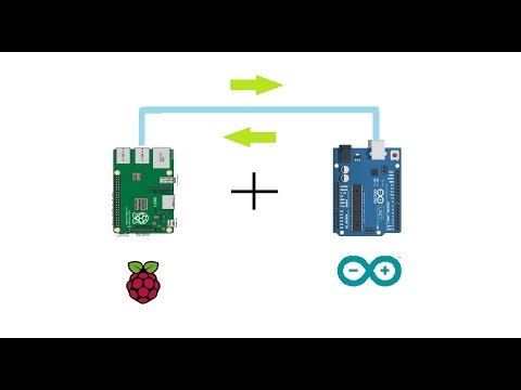
The circuit I want to disassemble:
Raspberry Pi 3 Model B + USB Arduino UNO R3
Steps:
- I burn the image of the operating system Raspbian to MicroSD
- I connect a minicomputer Raspberry Pi 3 to the monitor via an adapter HDMI to VGA , I also need a mouse and keyboard
- Connecting a network cable from my home router RB2011UiAS-2HnD
- Performing the initial setup of the minicomputer
- Enable remote connection via VNC and SSH
- Turn off monitor, mouse and keyboard
- Using a USB cable I connect a minicomputer Raspberry Pi 3 Model B with a Arduino UNO R3 board
- Next, I connect from my home laptop Lenovo E555 system Ubuntu Trusty Dekstop amd64 Gnome Classic via the Remmina client ( VNC connection) to the Raspberry Pi 3 Model B minicomputer.
I follow the command line console ( CTRL + ALT + T ) and set the development environment Arduino UNO R3:
PI@raspberrypi: ~ $ SUDO APT -GET Install ARDUINO --Y pi@raspberrypi:~ $ java -version
java version "1.8.0_65"
Java(TM) SE Runtime Environment (build 1.8.0_65-b17)
Java HotSpot(TM) Client VM (build 25.65-b01, mixed mode)
After I check how my microcontroller sees the board Arduino UNO R3:
pi@raspberrypi:~ $ lsusb | grep Arduino
Bus 001 Device 004: ID 2341:0043 Arduino SA Uno R3 (CDC ACM)
pi@raspberrypi:~ $ ls -l /dev/ttyACM0 3
crw-rw---- 1 root dialout 166, 0 Feb 25 22:02 /dev/ttyACM0
Now I launch the Arduino IDE development environment, through which you can already write sketches of the interaction of the board and connected to it: sensors , devices and everything that is needed, with this I move away from using the connection of the board to the laptop.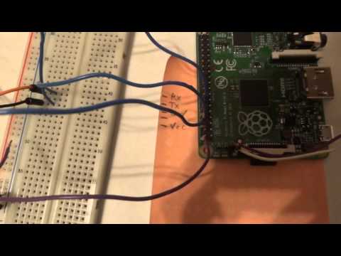
pi@raspberrypi:~ $ arduino or key Win → Electonics - Arduino IDE
0005 File, Edit, Sketch, Service, Help )
The fact is that when connecting via VNC the current resolution is too small to fix it:
pi@raspberrypi:~ $ sudo raspi-config
Advanced Options, Select - Resolution, Select - as I see the default resolution is: Default 720 x 480 , but on me at least use: DMT Mode 16 1024 × 768 60 Hz 4: 3 , I select it and I press Ok , The resolution is set to DMT mode 16 again click Ok and then Finish to complete the R aspberry Pi Software Configuration Tool configuration wizard. Here are just the changes to apply only after a reboot: Would you like to reboot now? I click Yes .
When the minicomputer boots up again, I connect to it via VNC and launch the development environment Arduino IDE everything becomes correct, everything is visible and you can not huddle in a limited space:
key (Windows) Win → Electronics - Arduino IDE
After overcoming the resolution problem, I boldly set about setting up the development environment for work. In the open development environment Arduino UNO:
- Tools - Board - choose Arduino UNO
- Tools - Serial Port - choose /dev/ttyACM0
That's all, now I can interact from the minicomputer through the development environment with board Arduino UNO R3 . But how to check this, and everything is simple, there are many examples in the development environment, and one of them: File - Examples - 01 Basics - Blink , this is a simple blinking of the LED opposite Pin No. 13 on the Arduino UNO R3 board.
So, the sketch is loaded and you need to upload it to the Atmega328P microprocessor:
- Sketch - Verify/Compile (or keyboard shortcut Ctrl + R )
- File - Upload (or keyboard shortcut Ctrl + U )
Everything is ready, then I turn my eyes to the Arduino UNO R3 board and see that the LED starts blinking opposite the digital PIN 13 . I have everything as it was intended, or rather, this is the simplest example of what to be modest here.
Next, you need to clear the microprocessor from this demonstration sketch. I create a new sketch with the following content: I check it and send it to the board
void setup(){}; nine0083
void loop(){};
All the contents of the microprocessor are cleared and ready for your projects or projects that you, like me, want to repeat, that have already been made by the community, and then make your own improvements based on them.
That's all for now, the note is over, and it's time to say goodbye, respectfully Ollo Alexander aka ekzorchik.
Saving ports (connecting buttons via i2c)
As you know, there are not many ports. Therefore, it is a pity to spend them on connecting banal buttons. Especially when there are a lot of buttons. nine0003
Everything has already been invented before us. The I2c bus allows you to connect up to 120 devices with just 2 pins on the RPi.
Moreover, there is a great thing: PCF8574(PCF8575). Remote 8-bit input-output expander of the I2C bus for 8 (16) ports, respectively. Here we will cling buttons to it.
The letter A in the marking defines the base address of the chip.
Letter P - package type (DIP1) Description of the chip for the curious
Pins A0-A2 allow you to change the address of the chip on the bus by driving them high or low. nine0003
Hint: Be sure to apply either 3.3V or ground to them.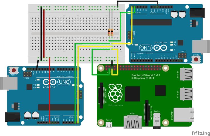 Unconnected outputs are the source of the most amusing glitches. VDD power supply + 3.3VVSS ground. SDA / SCL, respectively, I2C bus. P0-P7 8 additional ports. INT - an extremely useful thing - an interrupt output. Those. we do not have to constantly poll the chip to determine if the state of the ports has changed. It is enough to do this after the arrival of this very interruption 🙂 I hung 2 buttons on it on ports P4 and P5. Buttons short these ports to ground. Finished with iron. Further, everything is clear from the code and comments to it:
#!/usr/bin/python# -*- coding: utf-8 -*-# Chip address PCF8574i2c_addr = 0x20#
import the necessary libraries
import smbus as smbus
import RPIOfrom time
import *from subprocess
import Popen, PIPE
#configure I2C bus for functionsi2c = smbus.SMBus(1)# Configure GPIO port 25 and pull it to ground.
RPIO.setup(25, RPIO.IN, pull_up_down=RPIO.PUD_DOWN)# Here is what we do when the interrupt arrives def gpio_callback(gpio_id, val):
try :
# Read from PCF8574
temp = i2c.read_byte( i2c_addr)
print 'PCF8574 at address 0x{0:2x} READ 0x{1:2x}'.format( i2c_addr, temp )
except IOError : print 'PCF8574 Device not found at I2C address 0x{1:2x}'.format( i2c_addr )
error = 1
# Button pressed on port P4
if (hex(temp)== hex(0xdf)):
# Here I pull the screen, the connection of which I described in the last entry.
#p = Popen('/home/pi/mj/LCD-Char/LCD-Test-mj-v4.py Key=1 1 VAL=Press 2', stdout=PIPE, shell=True)
print("gpio %s: %s" % (gpio_id, val))
# Button pressed on port P5
if (hex(temp)== hex(0xef)):
#p = Popen('/home/pi/mj/LCD-Char/LCD-Test-mj-v4.py Key=2 1 VAL=Press 2', stdout=PIPE, shell=True)
print("gpio %s: %s" % (gpio_id, val))
# Both buttons are pressed at the same time
if (hex(temp)== hex(0xcf)):
#p = Popen('/home/pi/mj/LCD-Char/LCD-Test-mj-v4.py Key=1+2 1 VAL=Press 2', stdout=PIPE, shell=True)
print("gpio %s: %s" % (gpio_id, val))
flag=1
# Set up the port to wait for interrupts and execute the above function
RPIO.add_interrupt_callback(25, gpio_callback, pull_up_down=RPIO.