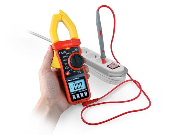
How To Measure DC Amps With a Clamp Meter
{% if result.isEmpty and result.term %}
{% if translation.search.not_found %}{{translation.search.not_found}}{% else %}Sorry, nothing found for{% endif %} {{result.term | escape}}
{% endif %}
{% if false and result.loading %}
{% else %}
{% if result.suggestions or result.collections or result.pages %}
{% if result.suggestions %}
{{keywords_suggestions_title | escape}}
-
{% for suggestion in result.suggestions %}
- {{suggestion.keyword | escape}}{{suggestion.count}}
{% endfor %}
{% endif %}
{% if result. collections %}
{{translation.search.collections | default: «Collections»}}
-
{% for collection in result.collections %}
- {{collection.title | escape}}
{% endfor %}
{% endif %}
{% endif %}
{% if result.products %}
{{products_suggestions_title}}
{% if result.term and result.isEmpty == false %}
{% if translation.search.view_all_products %}{{translation.search.view_all_products}}{% else %}View all products{% endif %}
{% endif %}
{% if product_list_layout == ‘carousel’ %}
{% for product in result.products %}
{% if product.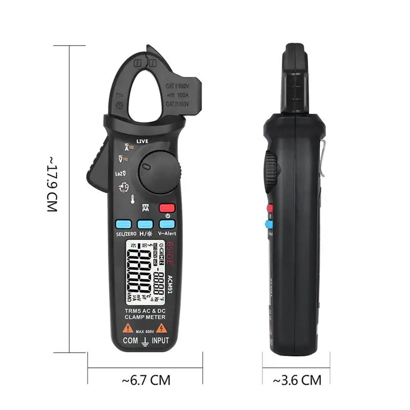 image %}
{% else %}
{% endif %}
{{product.title | escape}}
{{product.first_available_variant.sku}}
{{ product.price | money}}
{% endfor %}
{% else %}
{% for product in result.products %}
{% if product.image %}
{% else %}
{% endif %}
{{product.title | escape}}
{{product.first_available_variant.sku}}
{{ product.price | money}}
{% endfor %}
{% endif %}
{% endif %}
{% endif %}
{% if translation.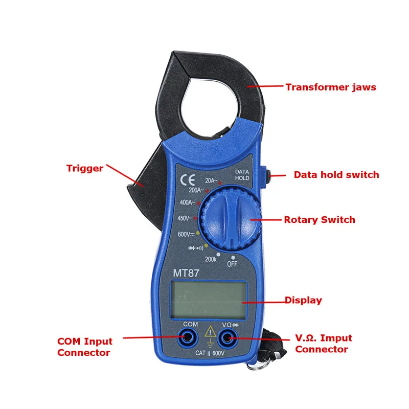 search.not_found %}{{translation.search.not_found }}{% else %}Sorry, nothing found for{% endif %} {{result.term | escape}}
multimeter — How does a DC clamp meter measure current?
Asked
Modified
5 years, 1 month ago
Viewed
25k times
\$\begingroup\$
I understand that for AC clamp meters, a changing magnetic field induces a voltage/current in a wire loop and therefore it is possible to measure AC currents by induction. But how does a DC clamp meter work? In essence a DC current means a static magnetic field, and by Faraday’s Law, no voltage/current is induced.
- multimeter
- amperage
- induction
\$\endgroup\$
\$\begingroup\$
This is one way of doing it.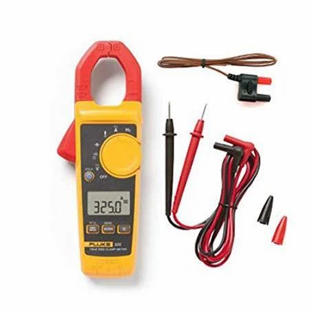 Ref
Ref
A normal transformer can’t deal with DC currents. Therefore the operating principle of DC current probes is rather different from AC probes. Here also is the current carrying conductor the primary winding and is inserted through the core opening. There is also a secondary winding, but now it functions as a compensation coil. The core is provided with an air gap that holds a sensor, e.g. a hall-sensor, which measures the magnetic flux in the core.
The current in the primary wire will magnetize the core. This magnetic field is measured with the sensor and as a result of this, the control circuit runs a current through the compensation winding in a way that the magnetic flux in the core is kept zero. As a result of this the core will never be magnetized. The advantage is that the non-linear properties and hysteresis of both the core and the magnetic sensor have little influence on the measurement results.
Beside the described measurement circuit there is also demagnetization circuit. Before using the current probe the core must be degaussed without wires inserted in the core.
Gain can be increased with compensation turns ratio at the expense of bandwidth.
Side Note
True RMS RF power meters work something like above, except instead of magnetic loop matching, they use a thermal resistor and using a bridge to compare RF heat with a DC heater for accurate measurements and obviously much lower bandwidth from thermal time constant, but very accurate.
\$\endgroup\$
2
\$\begingroup\$
Static magnetic fields can be measured with an Hall effect sensor.
\$\endgroup\$
2
\$\begingroup\$
If an AC clamp is put around a wire with DC current, a DC pulse occurs at the output of the winding of the clamp.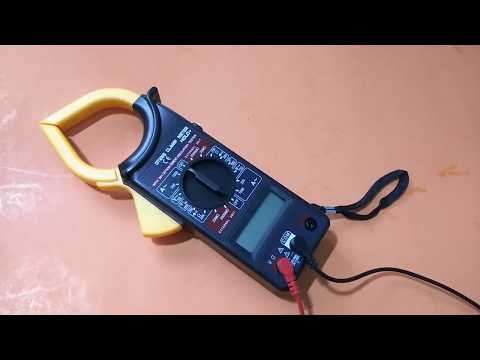 Feeding that pulse to an integrator gives the current because the pulse voltage is equal with the flux growth velocity through the winding and the final flux is proportional to the current.
\$\endgroup\$
Sign up or log in
Sign up using Google
Sign up using Facebook
Sign up using Email and Password
Post as a guest
Required, but never shown
Post as a guest
Required, but never shown
By clicking “Post Your Answer”, you agree to our terms of service, privacy policy and cookie policy
How to measure direct and alternating current with sensors and current clamps
Electric current — directed (ordered) movement of particles or quasi-particles — carriers of electric charge.
To expand the functionality of multimeters, oscilloscopes and other electrical measuring instruments, clamp-shaped current sensors are used — current clamps. To carry out measurements with tongs, they are closed in the girth of a current-carrying conductor, and thus, without breaking the circuit and without the need to cut any shunt into the conductor, measurements are taken. nine0003
It’s simple and convenient. The instrument displays the measurement result on its scale as a voltage or current proportional to the measured current. The advantage of the method lies in the fact that the device may not have a sufficiently wide input range, while the sensor — tongs is quite able to freely accept a conductor even with a very large current.
The conductor carrying the measured current not only remains intact, but is always galvanically isolated from the circuits of the measuring instrument. The device itself can have a very high impedance input circuit and even be grounded. There is no need to somehow regulate or turn on and off the power of the circuit, the parameters of which are measured by clamps, which means that there will be no downtime in the operation of the powered equipment. nine0003
RMS current over the frequency range of the sensor can be measured by using a current sensor with a multimeter capable of measuring RMS values. In this case, the range will be limited by the capabilities (scale) of the multimeter. Best results are achieved with transducers that have a wide frequency response, minimal phase shift and high accuracy.
For measuring AC parameters, sensors are used that work on the principle of a conventional measuring current transformer. Any transformer has primary and secondary windings installed on a common magnetic circuit. The primary voltage is applied to the primary winding, an alternating magnetic flux is created in the core, which induces in the secondary winding the EMF corresponding to the transformation ratio. The currents of the primary and secondary windings are related as the number of turns in the secondary and primary windings. nine0003
This is how an AC current sensor works. The magnetic circuit in the form of pincers closes around the conductor. The conductor is the primary winding, consisting of one single turn, the value of the current in which you need to know.
The current in the secondary winding will be proportional to the current in the conductor and differ from it by a factor equal to the transformation ratio, that is, as many times as there are turns in the secondary winding. The number of turns in the secondary winding of the sensor is usually 1000, 500 or 100.
If the sensor has 1000 turns, then the clamps have the designation 1000:1 or 1mA / A — this means that 1 mA in the instrument readings is identical to 1A in the conductor under study. Or 1A on the device — 1000 A in the conductor.
The ratio can in principle be different: 3000:5 or 2000:2, depending on the purpose of the instrument. However, in most cases, the pliers are paired with a conventional multimeter and the ratio is usually 1000:1.
At a ratio of 1000:1 or 1mA/A, the meter will read as follows. With an input current of 700A, the output reading will be 700mA, at 300A — 300mA, etc. This is because the output of the sensor is connected to a DMM in AC mode with the selected range of values. nine0003
To determine the effective current in the conductor, the multimeter reading is multiplied by the sensor factor. The main thing is that the measuring device has the required input impedance.
If the meter has a voltage-only input (voltmeter or oscilloscope), it can also be used with a current clamp sensor. To do this, the current output of the sensor must be coordinated with the input of the device, using the principle of a measuring current transformer. Then the AC voltage readings will be proportional to the measured AC current. nine0003
There are current clamps that can measure both AC and DC current. In such clamps, the principle of their operation is based on the Hall effect, when the parameters of the current are derived from the parameters of the magnetic field generated by it, which acts on the semiconductor and initiates the Hall effect in it.
A thin piece of semiconductor is placed perpendicular to the magnetic field of the current to be measured. An excitation current is applied to the plate in a certain direction (let’s say along it), which is deflected in an external magnetic field under the action of the Lorentz force in the transverse direction, and then in this direction the EMF (Hall voltage) can be measured at the edges of the plate. nine0003
With a constant excitation current through the plate, the Hall emf, as well as the magnetic field induction of the measured current, will be proportional to the measured current. That is, the Hall voltage corresponds to the current in the conductor, which passes inside the magnetic circuit of the sensor. Such a scheme has great advantages over devices based on a current transformer.
Since Hall EMF generation does not depend on the direction of the magnetic induction vector, but only on its magnitude, the Hall effect sensor measures both AC and DC current. In addition, the sensor absolutely accurately captures the phase of the change (direction) of the magnetic field, and therefore is suitable for observing the current waveform. nine0003
Hall sensor pliers are available with one or two built-in sensors. Various clamp models have a wide dynamic range and frequency response, signal linearity and high accuracy.
The scope of this clamp covers all equipment with direct current up to 1500 A without the need to build in expensive shunts. Alternating current with a frequency of tens of kilohertz can also be measured using clamps based on the Hall effect, and the shape of the current can be very different, the root mean square value will be found. nine0003
A millivolt output signal proportional to the measured current can be easily read by most multimeters, oscilloscopes and recorders.
ElektroVesti wrote earlier that the meeting of the heads of the USA and the USSR in 1985 gave the world one of the most ambitious technological projects: the experimental thermonuclear reactor ITER («way»). In Provence, in the south of France, thousands of scientists and builders are preparing a complex for scientific experiments that can open the way for humanity to the thermonuclear power plants of the future. nine0055
Source: electrik.info.
How to use current clamps »
Working principle of current clamps
The measuring principle is based on the current transformer or the Hall effect.
Clamp meter, working on the principle of a current transformer, measures only alternating current, because The transformer does not pass direct current through itself. The primary winding is a wire wrapped around a current clamp, and the secondary winding is inside a current clamp with a current sensor. Grab several turns of one conductor, then the current on the secondary winding will increase by the same amount. This is convenient for measuring small alternating currents, while dividing the obtained current value by the number of turns. Externally, current clamps operating on a current transformer are distinguished by the absence of notches on the jaws and the DC range. nine0003
Hall effect current clamp measures both DC and AC current. The principle of operation on the Hall effect is based on measuring the voltage on the edges of a semiconductor wafer through which a direct current flows, placed in a magnetic field perpendicular to it. A magnetic field is formed around the conductor, which is wrapped around the current clamp. A change in current in a conductor causes a change in the magnetic field around the conductor, which causes a change in voltage across the Hall sensing element. The voltage of the sensing element is converted and displayed on the screen as a current value. For current clamps operating on the hall effect, it is important to position the conductor perpendicular to the jaws of the current clamp. nine0003
Current measurement
To work on our APPA 133 device, select AC mode A~, grasp one wire. The selection of the measuring range in APPA 133 is automatic, in other devices it may be necessary to select the range. If the conductor is not placed perpendicularly or not according to the risks, then the reading error increases to 3%.
To measure AC inrush current, the «inrush current» mode must be selected, for example when measuring the inrush current of a motor. To measure the max min current, select the appropriate mode. When the stove is on, the maximum current is 8.47 A.
the sum of the currents of two conductors with different polarity is zero. If the meter reading is not zero, then there is a leakage current or the value is within the error of the meter. When measuring several wires at the same time, the current value will be the sum of the currents of all wires. Current leakage may occur, for example, if the water from the tap is electric, you need to check the leakage current of the electric boiler.
Voltage measurement
To measure DC and AC voltage, set the switch to V. Our device has an automatic range selection, and also allows you to measure the frequency. It is necessary to switch between modes with the wires disconnected. APPA 133 has over 1000V high voltage protection.
When the stove is on, we see that the voltage has dropped to 211.1 V, the frequency has not changed. This happened due to the fact that the cross section of the wires is not enough for the power of the stove, which causes overload and heating of the wires. It is necessary to change the wires to a thicker section.
Demand power measurement
Apparent power (VA) equals the square root of the sum of the squares of active and reactive power. Reactive power (Var) is equal to the product of voltage and current multiplied by the sine of the phase angle between them. If there are no consumers with reactive power (motors, transformers), then the total load power will be equal to the active power.