Super Starter Kit V3.0 for Raspberry Pi, Including 123-Page Instructio
Save 0
SunFounderSKU: CZ0125D
filler
Share this product
This is a magical tool kit with various components inside for learning, which will lead you to the world of Raspberry Pi quickly. It includes 17 lessons, each containing the circuit connection, principles, Fritzing images, and code explanations for you to learn Raspberry Pi from scratch.
Access the online tutorial for Super Starter Kit V3.0 for Raspberry Pi.
1. Order processing times
All orders are processed within 24 hours after they are placed. Usually, we are able to ship orders the next day. Weekend orders are shipped on the following Monday. You will receive a shipping confirmation email from our system when the shipping information has been uploaded.
2. Free Shipping on ALL orders
Generally, we will ship the orders with Free Shipping, without the minimum order amount requirement. You may check if the free shipping method is available to your country in the Delivery Area below.
If you don’t find your country in the delivery area, please reach out to [email protected], our sales staff will contact you ASAP.
For distributors, please contact us at [email protected] for more shipment details.
NOTE: All the orders will be shipped from our China warehouse.
3. Delivery Area
Asia
Hong Kong SAR, Japan, Macao SAR, Malaysia, Philippines, Russia, Singapore, South Korea, Thailand, Vietnam, etc.
Europe
Austria, Belgium, Czechia, Denmark, Finland, France, Germany, Greece, Hungary, Italy, Lithuania, Luxembourg, Monaco, Netherlands, Norway, Poland, Portugal, Slovakia, Slovenia, Spain, Sweden, Switzerland, Turkey, Ukraine, United Kingdom, etc.
Oceania
Australia, New Zealand
North America
Canada, Mexico, United States
4. How do I track my order?
GOT A SUNFOUNDER ACCOUNT?
Easy Peasy! Log into your account through the online store, check out the fulfilment status against your recent order. If the order has been fulfilled, click onto the order information & you can find your tracking information here.
I DON’T HAVE AN ACCOUNT YET
As soon as your order is packed and shipped, you’ll receive a shipping confirmation email. You will then be able to track your order through the tracking link on the email. If you haven’t received an email yet, please reach out to us at service@sunfounder.com, our sales staff will contact you ASAP.
5. Shipping Method and Delivery Times
DHL(Orders Over $400)
Delivery Time: 3-7 working days
You can track on http://www.dhl.com/ or https://www.17track.net/en
UPS(Orders Over $400)
Delivery Time: 3-7 working days
You can track on https://www. ups.com/track or https://www.17track.net/en
USPS
Delivery Time: 7-12 working days
You can track on https://www.usps.com/ or https://www.17track.net/en
REGISTERED AIRMAIL
Delivery Time: 12-15 working days
You can track on https://www.17track.net/en
* Delivery Time — These are the delivery estimates provided by our shipping partners and apply from point of dispatch, not from point of sale. Once your parcel leaves our warehouse, we cannot control any delays after that point.
6. Customs & Import fees
Such as the products you buy on our site — can’t simply be shipped freely from country to country. When goods are imported into a different country or customs territory, there is a charge called Customs Duty that must apply. This is charged by the local customs authority where the goods are being imported into.
If Customs Duty is payable to your territory, you’ll be responsible for paying it to the authorities, so SunFounder isn’t involved in this process. Whether Customs Duty is payable, and by how much, depends on a whole lot of different things. For example, many countries have a ‘low value threshold’ below which they do not charge any Customs Duty.
If you do have to pay Customs Duty though, the amount payable is usually calculated based on the value of the goods and the type of goods being imported.
AND IF I DON’T PAY THE CUSTOMS DUTY?
If, for whatever reason, you refuse the customs fee and the parcel is returned back to us. If you’re still unsure on whether you’ll be subject to customs fees, we recommend contacting your local customs office for more info before placing your order!
PayPal
Your payment information is processed securely. We do not store credit card details nor have access to your credit card information.
Super SIM, Raspberry Pi 4, and the Waveshare 4G Hat Getting Started Guide
Twilio Super SIM can empower a huge range of IoT devices. This guide focuses on just one of them: Waveshare’s SIM7600G-H 4G Hat, a development board which equips a low-cost Raspberry Pi computer with a Simcom 7600G-H cellular modem.
In addition to your configured Super SIM, you will need the following hardware to proceed with this guide:
- A Waveshare SIM7600G-H 4G HAT. This is the global version; there are variants that target specific territories.
- A Raspberry Pi. This guide was written using the Pi 4 Model B, but there are other versions of the Pi available — it should work with any of them, but we’ve only tested the 4. The SIM7600G-H 4G Hat works with all but the very first Pi. To run the Pi, you will also need:
- A Micro SD card of 8GB or above.
- A monitor and an HDMI-to-micro-HDMI cable.
- A keyboard and a mouse
- A 5V, 2A (10W) USB-C AC adaptor.
Hardware setup: the Raspberry Pi
The Raspberry Pi has its own setup procedure which involves downloading and installing its Linux operating system, called Raspberry Pi OS, onto the Micro SD card. The Raspberry Pi Foundation has a very good walkthrough of its own that covers this process — you should use this to get your Pi ready before proceeding to the next stage of this guide.
During setup you should connect your Pi 4 to your WiFi network as you will need to download extra software later. We’ll disable WiFi in due course to demonstrate data access over cellular.
Hardware setup: the SIM7600G-H 4G Hat
The SIM7600G-H 4G Hat ships with all you need to fit it onto the Pi. Just follow these steps to set everything up:
- Fit your Super SIM into the SIM7600G-H 4G Hat’s SIM retainer. This takes a full-size SIM, so take care removing your Super SIM from its mount, or use an adapter if you have removed the Super SIM as a 4FF Nano SIM:
Lock the SIM retainer in place to keep the Super SIM secure:
- If it’s powered up, turn off the Pi.
- If you’re at the command line, enter
sudo shutdown -hnow. - If you’re at the desktop, select Shutdown… from the Raspberry menu and then click Shutdown.
- Remove the power cable when the Pi’s activity LED has flashed ten times.
- If you’re at the command line, enter
- Slot the SIM7600G-H 4G Hat onto the Pi’s GPIO header:
- Connect the supplied USB cable to the micro USB port marked just USB on the SIM7600G-H 4G Hat and a USB port on the Pi:
- Assemble and connect the bundled cellular antenna to the SIM7600G-H 4G Hat. Connect it to the LTE connector marked MAIN on the board:
Here’s a close-up:
- Finally, power up the Pi by re-inserting the power cable.
We now need to run through a few steps to get the Pi ready to talk to the SIM7600G-H 4G Hat. Some of these will require you to restart the Pi.
1. Configure Pi serial port access
- If you’re at the Raspberry Pi desktop, select Accessories > Terminal from the Raspberry menu.
- Run
sudo raspi-config. - Use the cursor keys to highlight Interfacing Options, then hit Enter:
- Now highlight Serial Port and hit Enter:
- When you are asked Would you like a login shell to be accessible over serial? select No and hit Enter:
- When you are asked Would you like the serial port hardware to be enabled? select Yes and hit Enter:
- Select Finish.
- The
raspi-configutility will offer to restart the Pi — accept its suggestion.
2. Power up the Hat
When the Pi is back up, you should see that the SIM7600G-H 4G Hat’s PWR LED is lit. Now press the PWRKEY button on the board — after a brief moment, the NET LED should light up.
At the command line or in a desktop Terminal run:
ls /dev/ttyUSB*
You should see a list of items all beginning with ttyUSB and including ttyUSB2, which is the device you’ll use in subsequent steps. If you don’t see a list of TTYs, first check that the SIM7600G-H 4G Hat’s PWR and NET LEDs are lit. Make sure your USB cable is not connected to USB TO UART on the Hat.
3. Attach to a cellular network
The SIM7600G-H 4G Hat can be controlled using AT commands issued through a command-line serial console tool which communicates with the Hat’s cellular module. We’ll use Minicom here, but if you prefer to use an alternative tool, such as Screen, that’s fine. At the command line or in a desktop Terminal run:
sudo apt update
sudo apt install minicom -y
Enter minicom -D /dev/ttyUSB2 to open a connection to the modem. If Minicom posts an error indicating that /dev/ttyUSB2 is inaccessible, please check your SIM7600G-H 4G Hat setup.
The SIM7600G-H may not be set to echo back what you type in, so you won’t be able to see your side of the conversation. Type in ATE1 and hit Enter. You’ll get an OK back, and when you follow the remaining steps you’ll see what you type!
Just hit Enter after keying in each of the following commands. Wait for the modem to respond before moving on to the next command.
AT+CGDCONT=1,"IP","super"
AT+COPS?
You should see something like +COPS: 0,0,"Vodafone UK Twilio",7 which tells you which network you’re connecting through. You should also see the Hat’s NET light flashing.
4. Connect to the Internet
Now you know you have a cellular connection, you can connect to the Internet. You need to install the PPP (Point-to-Point Protocol) software the PI will use to establish the connection, and to configure it. First run the following commands at the command line:
sudo apt install ppp -y
sudo cp /etc/ppp/peers/provider /etc/ppp/peers/provider.bak
sudo nano /etc/ppp/peers/provider
The last of these commands opens the primary configuration file in a text editor so you can make the required changes. Make sure the file contains the following lines. Some may be missing, others may be present depending on the version of ppp you’ve installed:
nocrtscts
debug
nodetach
ipcp-accept-local
ipcp-accept-remote
In the same file, look for lines like these and update them so they match what’s shown here:
connect '/usr/sbin/chat -s -v -f /etc/chatscripts/gprs -T super'
/dev/ttyUSB2
The last line above is the value you determined earlier.
To initiate an Internet connection, at the command line or in a desktop terminal run:
sudo pon
You’ll see a stack of lines displayed at the command line.
Meantime, open a fresh terminal and enter:
sudo route add -net "0.0.0.0" ppp0
When the prompt is back, you’re ready to try out the Internet connection:
- If you’re at the desktop, select Turn off Wireless LAN from the network menu at the top right.
- If you’re at the command line, run
sudo ifconfig wlan0 down. - At the command line or in a desktop terminal, enter
ifconfigand look for theppp0entry — it should have a valid IP address listed underinet: - Open up a browser and navigate to twilio.com/docs/iot:
Well done! You now have a Raspberry Pi computer that’s connected to the Internet via Twilio Super SIM. You can now start experimenting with cellular Internet connectivity, or begin developing your own IoT application proof-of-concept.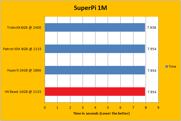
Your Raspberry Pi and Waveshare SIM7600G-H 4G Hat are now able to access the cellular network. Over to you: what are you going to build? We can’t wait to find out.
In the meantime, here are some suggestions for things to try:
- Write some code to get data from a cloud service API via cellular. Here’s a good selection of public APIs.
- Use the Console or Super SIM API to monitor your Super SIM’s data usage.
- Check out our guide Introduction to AT commands and try sending to your modem some of the more useful commands it lists.
Rate this page:
1
2
3
4
5
Need some help?
We all do sometimes; code is hard. Get help now from our support team, or lean on the wisdom of the crowd by visiting Twilio’s Stack Overflow Collective or browsing the Twilio tag on Stack Overflow.
- Terms of Service
- Privacy Policy
- Copyright © 2022 Twilio Inc.
Super Pi Boy
Getting Started!
I had recently bought an original Gameboy DMG from Good Will for a whopping $5. 00, condition unknown. Taking a gamble, I purchased it and took it home to find that it had severe damage caused by a battery that exploded and leaked all over the mainboard.
I had also recently started looking on eBay for the elusive Gameboy Light. It’s a system I have always wanted but could never allow myself to buy since they are pretty expensive on eBay. The Gameboy Light is the Gameboy Pocket with an Indiglo light and was only released overseas in Japan.
I had bought a Raspberry Pi a while back and really didn’t know what I wanted to do with it. At that moment, like a Reese’s Peanut Butter cup, it dawned on me – could the Raspberry Pi be used with a Gameboy?
The Raspberry Pi is a small ARM based computer that fits in the palm of a normal adult hand. The great thing about the Pi is that it has several ways to connect I/O for video, audio, network, USB as well as a direct I/O set of pins called the GPIO pins.
After doing some research, I came to the conclusion that this project might actually be conceivable. Everything I needed was there, it was a matter of getting things together and working out the hardware as well as software side of things. That’s where this guide comes in. It’s my attempt to pass on what I’ve learned as well as taking you through the various steps I took to make it a reality. First off, the parts…
The Parts List
Hardware
- Pi Model B
- 3.5″ LCD Backup Screen
- Controller PCB
- 3 Watt Audio Amplifier
- Rear Buttons
- Power Switch
- Female to Male Micro USB Cable
- Broken Gameboy DMG (please don’t sacrifice a perfectly good working one)
Software
- Retropie (Emulation)
- Retrogame Program (map GPIO to keys)
Tools
- Tri-Wing Screwdriver for Gameboy Case
- Dremel
- Soldering Iron
- Solder
- Wire Cutters
- Electrical Tape
- Hot Glue Gun
- Electrical Wire
- Exacto Knife
- Patience…
The Case
The first thing that had to be done was to see if the Pi would even fit into the case.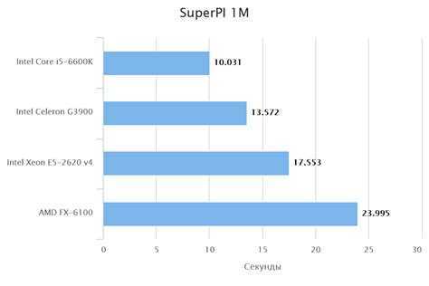 I found that the Pi sits almost perfectly on the back case of the Gameboy. The width of the Pi fits snug down the center of the case, but in order for it to fit, some modifications had to be done to the case itself.
Using a Dremel, I cut out a most of the battery compartment as well as some posts that on the case for the LCD that would no longer be needed. Doing so, the Pi sits flush with the back of the DMG case:
In the picture above, the battery compartment is on the left and the cartridge slot is on the right. I had to cut back the Cartridge slot as well in order to allow the GPIO pins to fit.
I had initially cut a slot on the left thinking I would add a wireless keyboard or network dongle which can still be added. This would use additional power which means more drain on the battery so those were left out.
LESSON LEARNED – given that, I probably should have de-soldered the Network and USB ports to slim up the Pi which would have allowed for more room to work with.
The Screen
The screen was the first challenge. The screen runs off 12V out of the box which wouldn’t work with the USB battery pack. The USB battery pack is rated at 5V, 1000mAH so the goal was go modify the screen to allow it to run at 5V.
Luckily, there is a great thread here: http://www.raspberrypi.org/forums/viewtopic.php?f=41&t=17651 which details how to modify the PCB for the screen to run at 5V instead of 12. The problem with these screens is that there seem to be several versions of the PCB controller boards which require different approaches.
For my particular setup, the board came with the 4 wires (yellow, white, black and red) all soldered onto the PCB. I found a board in the thread above that matched my board, but I still had some difficulties getting the board to run off of 5 volts.
I finally got it to work by removing the power converter chip as well as soldering a jumper between the + power in and the capacitor on the top right as seen below:
The next step was to hook a composite input to the screen PCB board. For this, I took a composite wire I had and stripped off the connector to create a smaller connector that would fit into the Pi’s female composite port. The Pi composite input could have been de-soldered, but I chose this approach to allow it to be unplugged from the Pi if needed.
The Yellow wire from the LCD Controller is soldered into the Composite input. The Black wire (ground) is soldered from the LCD Controller board as well and then wired to the male composite connector. You can see the connector on the left side of the image below
After this was completed, the screen and Pi were plugged into a 5V USB input and tested.
Success!
The next challenge was fitting the LCD and controller board to fin in the case. I initially wanted to keep the size of the original Gameboy window and add on a new screen protector. I tried orienting the screen in a portrait layout, but this proved problematic with Retropie.
Editing the root “config.txt”, you have the ability to rotate the screen as well as adjusting the overscan of the screen. The config.txt file can be edited directly from your SD card with any PC. Here is a handy guide to the various settings that can be tweaked and adjusted in the config.txt: http://elinux.org/RPiconfig
None of the adjustments made yielded a layout that would fit correctly within the Gameboy’s window. I made the decision to go ahead and cut out the window to allow the screen to be displayed.
This also meant that I would have to layout the screen in a landscape orientation. This would not work without some trimming of the LCD Controller board since it’s wider than the width of the Gameboy. The parts outlined in red below are what needed to be cut to get the board to fit.
After multiple cuts and trims, I found that I was able to BARELY fit the Controller Board into the case. It only fits because part of the controller board sits in the position where the original Gameboy Contrast knob used to sit. However, it does fit!
For the LCD, I used black electrical tape to cover up the silver border of the screen. Once this is done, I used some double sided stick padded tape and trimmed it to form a border around the LCD and then mounted it to the case.
The Controls
After getting the screen to work, the next step was to get the controls to work. I decided that I would try to use the Pi’s GPIO inputs instead of getting something like a Teensy board. Adding another board would mean that I would have to find room in the cramped DMG case and the GPIO pins are already there, waiting to be used!
I stumbled on a company that creates Controller boards for DMG Gameboy’s that works perfectly with this setup. Instead of having to take the original Gameboy PCB, cutting it and having to solder in wires, the Kitsch Bent PCB allowed me to solder directly to inputs built right into the PCB.
Below is the Controller PCB. The PCB screws into the existing Gameboy mounting posts so the original buttons and rubber fit right in like the stock board would fit. The arrow points to the solder points with each point clearly marked off with it’s respective control function. This makes it easy to associate a control to a solder point which was tied to a specific GPIO pin.
The other advantage of this was that the Kitsch Bent version uses a common ground. This meant that I only need one ground wire for all of the buttons.
Initially I had bought some wires with female to female connectors that I thought I could just plug into the GPIO pins with. This proved to be a failure since the wires sat too high and could not be bent. I decided to strip the wires and solder them directly to the GPIO pins. This proved to be a mistake that caused me unneeded work and issues when trying to assemble everything together.
LESSON LEARNED – I should have bought a GPIO ribbon cable similar to this: http://www.adafruit.com/products/1337. This would have been a simple plug and go solution instead of the pain of soldering the wires to the pins and having them pull off as I tried to work around things.
Once the pins were all soldered to each of the wires, it was time to setup the Retrogame program that would handle each of the input controls.
I followed this guide https://learn.adafruit.com/retro-gaming-with-raspberry-pi/buttons which details the steps needed to map a GPIO input to a corresponding keyboard key. I mapped out the keys based on the following which worked out great for all of the inputs I needed:
Once the program was updated, I compiled the updated version of the code and added the entry to autostart as the Pi booted. I had to make a couple of adjustments for the ESC key in Retropie and had to double map the A button to on the Gameboy to be an S on the keyboard as well since the PC Engine emulator seemed to want to use the keyboard S key as one of it’s buttons.
I also decided that I needed some extra controls since I intendedto run the Gameboy Advance emulator as well which would need shoulder buttons. I decided to mount to buttons I found at Radio Shack that would work.
The position of the buttons seems to work better than putting them on the side. My middle fingers fall onto these buttons with the natural grip of the DMG case which works great. These buttons also map to the Page Up/Page Down keyboard keys which I use for paging back and forward through the ROM lists.
For these buttons, these each needed their own ground so I used some of the free GPIO ground pins for each. You can see these in the GPIO mapping diagram above.
Audio
The first thing I had to do was figure out a way to connect to the Pi’s audio out port. I considered de-soldering, but utltimately found that I could just take an old pair of earphones and cut the Input Jack’s rubber shielding to expose a pin with 2 solder points that I could wire to. This allowed me to use an Earphone Jack to essentially plug into the Pi’s audio out jack without desoldering anything. Doing this, I wired directly to the speakers at first only to find that the sound was… lacking!
I ended up ordering an Audio Amplifier board from eBay (above) and connected it to the Pi’s Audio out. The Audio Amplifier requires 5 Volts of power to run, so I soldered wires from the LCD Controller Board’s Positve solder point to the +5V/Ground of the Audio Amplifier.
I wired in the wires from the Pi’s Audio out to the RIN/GND (bottom left of the Audio Amplifier board) and then wired the speaker to the R+/R- (top left of Audio Amplifer board). This drastically improves the loudness of the speakers.
I had originally wanted to use the Gameboy’s Sound Control potentiometer, but it was impossible to find a way to mount and I ended up just scrapping that idea.
Retropie includes a Volume adjustment bar in it’s menu so that’s how volume is controlled.
The Emulators
This was somewhat simple and can be summed up with one word – Retropie. You can download bootable image which can be written to an SD card which will provide you with the Raspian operating system as well as it auto booting to Retropie. Check out the Retropie forums for more details on installing, configuring and troubleshooting Retropie.
Wiring the Beast Together
Here is the wiring schematic for how everything was tied together:
The battery is connected to a Female Micro USB port that I hot glued into place. I modified the port where the Headphone jack was located widening it so that the Female Micro USB adapter would fit.
(1) The Female Micro USB Positive (RED) wired is then fed to the On/Off Switch. From the switch, the Positive (RED) wire is soldered to the positive solder point on the LCD Controller Board.
The Ground (BLACK) from he Micro USB port is wired directly to the negative solder point on the LCD Controller board.
(2) The Positive (RED) and Negative (BLACK) wires are then wired from the Positve/Negative points on the LCD Controller board and then wired to the Micro USB Male pin that is plugged into the PI.
The Audio Amplifier is also wired to the Positive/Negative points on the LCD Controller Board. The Positive (RED) wire is connected to the +5V solder point on the Audio Amplifier and the ground (BLACK) is wired to the GND right above the +5V solder point on the Audtio Amplifier. Since the LCD is power in runs through the switch, anytime the switch is flipped, the LCD, PI and Audio Amplifier are all turned on or off at the same time.
(3) For video, the positive Composite wire (YELLOW) is wired to the positive solder point on the Composite connection plug. A Negative (BLACK) wire is also soldered between the LCD Controller board and the solder point on the Composite connection plug.
(4) The audio Amplifier is connected to an Audio input jack by connecting the Positive (LIGHT BLUE) and Negative (BLACK) to the GND and RIN solder points on the Audio Amplifier.
(5) the R+ is wired (ORANGE) to one solder point on the speaker and the R- (GREEN) is wired to the other solder point on the speaker.
Overview Videos
Part 1:
Final Thoughts…
I love my “Super Mega Ultra Pi Boy 64 Thingy”! It was a lot of fun to build and was well worth it. I recommend just taking your time and doing some research before just jumping in. I’ve tried to layout as much as I could above, but if you have any questions, please leave them in the comments below!
Also, if you build your own version of this project, I would love to see it as well!
Thanks for reading…
Helpful Links
- Raspberry Pi Gameboy Pocket Documentation – AMAZING Pi Gameboy Pocket mod with some excellent build details
- The GamePi Gameboy Case Mod
- Game Boy PC
- PiBoy Advance
- RasppiBoy
- Adafruit Soldering Guide
Super PI
About the program.
 History of the Super Pi.
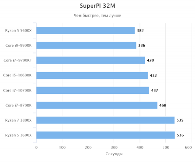
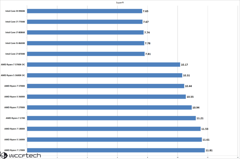
Super PI is a benchmark designed to measure the processing power of a processor and uses the algorithm to calculate the number π . The result is considered the better, the less time the calculation of the given number of decimal places of the number π takes place.
The first to calculate the number π using the computer G.W. Reitwiesner at 1949, the calculation accuracy was 2,037 decimal places. Calculations were made on computer ENIAC . The first calculation to 500,000 decimal places was made by J. Guilloud and M. Dichampt in 1967 on the CDC 6600 computer. After that, in 1973, 1,001,250 decimal places were calculated — J. Guilloud and M. Bouyer on computer CDC 7600 . Another world record was set by the Tokyo University of Information Science, D.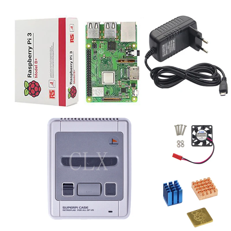 Takahashi and Y. Kanada in 1995, 4,294,960,000 (think about that number!), the computer used is HITAC S-3800/480 (two-processor system).
The program was developed in 1995 at the University of Tokyo «Information Science» (Laboratory research areas: High Performance Computing and Computer Algebra). The development process was led by Associate Professor Yasumasa Kanada and Research Fellow Akira Yoshioka, with active participation of graduate students of this university. The first version was called Super PI 0.1 , the version that was released is Super PI 1.0 . What we call Super PI is a Windows ported version of a Fortran-to-C program. The program first gained popularity among Japanese overclockers, but then it began to be used all over the world.
Algorithm. Getting to know the interface.
Super PI uses the Gauss-Legendre algorithm (also called the Brent-Salamin algorithm). Initial condition:
Iterations are repeated until the difference between A and B does not satisfy the required accuracy:
π is approximated by the following expression:
The first three iterations will give the following results:
- 3.140 …
- 3.14159264
- 3.1415926535897932382…
11
The algorithm has a second order of approximation, so the number of decimal places obtained doubles with each step of the algorithm. Because zero iteration computes 2 digits of 919= 1M decimal places and 24 iterations up to 32M .
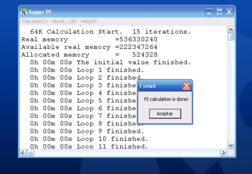
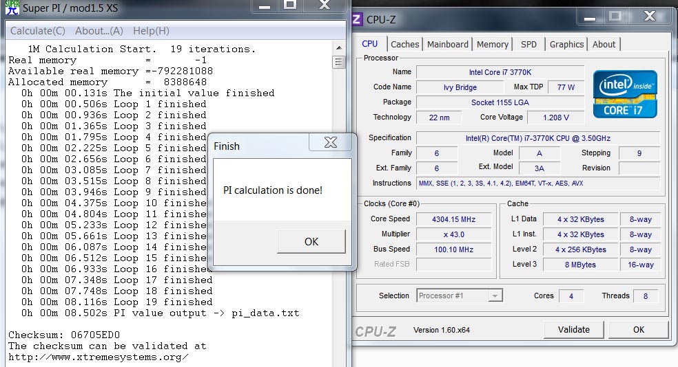
The test itself consists of one file — Super Pi.exe . Running it, we will see the following window:
In the title of the window we see the name of the version, « mod1.5 XS «, followed by three buttons and the results of each subtest.
The « Help » button calls the help file super_pi. hlp , so you shouldn’t be surprised by the reaction of the program if you don’t have it and there are only 9 in the folder0006 Super_Pi.exe . The button « about » brings up a window where the author of the program briefly talks about the history of the test.
When you click on the button » Calculate ( C ) «, or Alt + C in the English layout, we will see a window with a combo box to select the number of decimal places for the calculation. Select the required precision and press « OK «. The choice is usually between accuracy 1M and 32M , since they are accepted by HWBot.org and are the de facto standards in benchmarking.
Next, we get a window where it says that the calculation will now begin with the specified accuracy, with which we agree.
The result with the window about the completion of the calculation (that is, without clicking anything in the test) is saved, usually together with two windows CPU-Z (CPU and memory).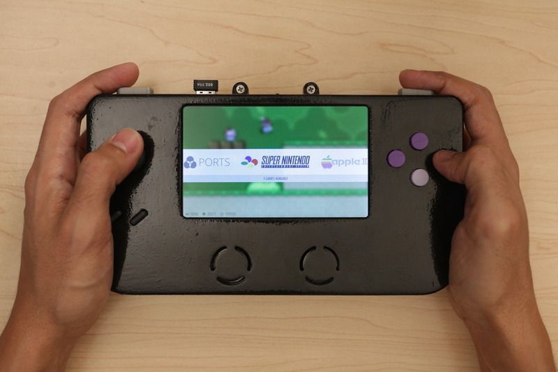
Stability test. Version history.
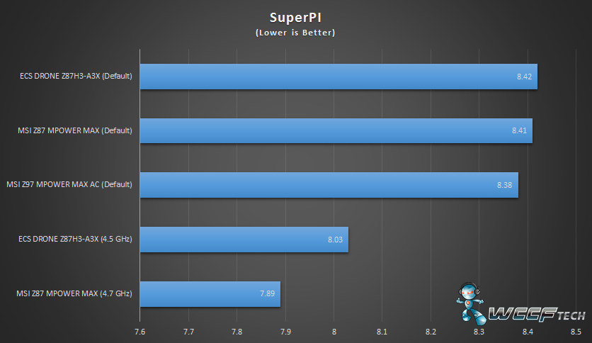
The Super PI test is also used as a tool to measure system stability. For example, distinguish » 1M stable «- the ability to pass the short Super PI test and » 32M stable » — the ability to pass the long Super PI test. The long pi test indicates the relative stability of the memory subsystem overclocking and is used for the initial assessment of frequencies and stability settings. , do not forget that the test is single-threaded, and therefore in the realities of the multi-core era, its relevance as a stress test decreases. better suited for this.0006
Version history
- Super PI 1.1 — the version thanks to which the program became known to everyone. Counted the result only with an accuracy of seconds and was not protected from hacking
- Super PI mod 1.4 — differed from the previous one in that it showed the calculation time with an accuracy of thousandths of a second, which increased its value for measuring the speed of more and more productive hardware
- Super PI mod 1.
 4 + cheksum validator — similar to the previous one, but added the creation of a checksum of the calculation time and the ability to register the result on the site. Also made protection against cheats — when detecting such an attempt, the program «crashes»
 - Super PI mod XS 1.5 — made on the basis of version 1.4 , but the algorithm for calculating the number π has been improved (the sequence of actions has been improved) and registration has been made on the website XS
- Super PI mod 1.6 — made by enthusiasts from site techPowerUp! based on version 1.5 XS . Fixed a bug when working with Windows Vista and changed the address of the validation site
- Super PI SSE2 — based on version 1.1 , but calculation uses stream instructions SSE2
- Super PI SSE3 — similar, but added support for SSE3 instructions
Optimization
Hardware optimization tips
- The most obvious is overclocking the processor, the more the better.
 The test (especially the short π ) is extremely frequency sensitive. At the same time, remember that the test is single-threaded and, if possible, lower the frequency or disable the remaining cores
 - frequency and memory timings. The frequency is more important for the long test π (32M). For short, the balance of frequency and timings is optimal
- multi-channel memory access mode — three channels, for example, for LGA1366 and two for all others
- memory size. An interesting point — for older systems it is important in that a lot of memory is required to calculate 32M — it is desirable to have a volume exceeding 256MB. For new systems, it is important for the operation of the memory bank interleaving mechanism. The more memory banks installed in the system, the higher the speed of the memory. The easiest way to double the number of memory banks is to use double-sided modules, such as 2GB DDR3 instead of 1GB DDR3. This explains the speed difference between 3GB and 6GB LGA1366 systems.
 It is worth noting that a larger amount of memory overclocks worse due to a larger number of chips per memory channel (due to parasitic capacitance), as well as another technology (when using denser chips, for example, 512Mbit DDR2 chips versus 1Gbit chips)
 - Do not update processor microcode. This is done, for example, by flashing a BIOS version that does not support this family of processors, or by turning off the corresponding item in the BIOS (if available)
OS optimization tips
The first thing to consider is that the effect of a particular tweak depends on the specific platform and processor core. Sometimes the effect can even be negative on some systems. Thus, experience is the criterion of truth in this matter. For a short test, they usually prefer to use Windows XP, and for a long test, Windows Server 2003.
- distribution modification with nLite. Here you have to be careful, so that, like a surgeon, do not cut off the excess.
 We need the NTFS file system (since this benchmark is far from being used on the most stable system, the high reliability of the file subsystem is important for us) with the maximum cluster size in the disk partition. After formatting, you will need to create a file with a total volume of 512/1024MB, depending on the amount of RAM, so that later the swap file can be left at the beginning of the disk. After we have installed the operating system, we make the paging file zero and reboot. Next, delete that large file and set a fixed swap size and reboot. And only after that we defragment everything from safe mode or another OS
 - Using an Asian version of Windows (Chinese or Japanese)
- Installing any drivers is not recommended
- There are suggestions to set a lower resolution and a 16-bit color palette
- further we will advise two cult articles: Windows2000/XP/2003 Configuration Guide and Windows2000/XP/2003 Services Configuration. Do not forget that disabling services may not always have a positive effect on the result (especially for the short π ).
 For Superpi 32M usually gives an increase of
 - Defragmentation by third party utilities (helps for Super PI 1M due to swap file defragmentation) such as O&O. It is recommended to defragment after each removal of system files
- Setting maxmem=104. It is done as follows — Start => Run => msconfig. Select the boot.ini tab => Advanced => Select the /MAXMEM= checkbox and set the value to 104 for Super PI 1M. Super PI 32M is usually set to 600MB
- Setting the secondlevelcache and largesystemcache parameters in the registry (see the article about configuring WinXP). The keys » ClearPageFileAtShutdown»=dword:00000001 , » EnableSuperfetch»=dword:00000001 can also help (unlike the previous ones, it is added not to MemoryManagement, but to MemoryManagement\PrefetchParameters)
- stop the explorer.exe and userinit.exe processes (they are killed through the task manager, after the run you can start it in it)
- for 32M you can use Ramdisk, because temporary calculation files and the final number file are written to disk, which can lead to slowdowns
- disable paging file (usually helps on Super PI 32M)
- diagnostic mode — set in msconfig.
 Starting the safe mode leads to a negative effect, and the diagnostic mode usually does not bring any benefit (but you never know)
 - Use of silver color scheme and «Windows XP» style for windows (Luna silver theme).
- Turn off hardware acceleration: «Properties:Display»=>Settings=>Advanced=>Diagnostics=>Hardware acceleration. We expose to the extreme left position
- Switching the keyboard layout to a language other than the OS language
Super PI run optimization tips:
- Real time priority for Superpi.exe process (does not always work)
- Binding a Super PI process to one non-null core. Done by task manager by right clicking on process superpi.exe => match. Due to the fact that all system processes are usually executed on the very first core
- Copywaza (copywaza) — a tweak that consists in copying a large file that exceeds the amount of RAM from one disk to another.
To simplify the use of this tweak, a program was written OCX Spi Tweaker , which we recommend using. Most often, they use a file size of the order of 1.8-2.0GB and copy the file from the second partition to the first, where the OS and Super PI are located. Then wait a couple of seconds, run 16K and then run 32M
- Often, not the first run of the test is faster, but the second or third. It is possible that this procedure simply creates a situation similar to Kopivase, since when using it, the first run of
- Minimizing the window can also help with Super PI result
- Instead of minimizing, you can reduce the size of the window by dragging its lower right corner to the bar in the header. Next, use the alt + C combination to call the launch window
- When the system is overclocked, it often happens that the calculation stops with an error message like “ not exact in round ”, “ non convergent in sqrt ”.
In this case, you need to close the test and run it again — otherwise the error will occur every time you run it. Alternatively, you can simply delete the temporary files with calculations that are in the folder with the program
is usually the best
View world records in the Super PI benchmark at HWBot.org for 1M and 32M respectively.
You can discuss the material here
Ballpoint pen with grip BRAUBERG SUPER, BLUE, body red, knot 0.7 mm, pi line
Ballpoint pen with grip BRAUBERG SUPER, BLUE, body red, knot 0.7 mm, pi line — buy for office and home
Catalog
|
Office supplies
|
Paper
|
Cartridges and toners
|
Household goods
|
Overalls
|
Study and creativity
|
Other products in this category
insecticide and acaricide «LODI Super PB (LODI Super Pee B)» also under the trade names: «PHOBI Super EC (FOBI SUPER KE)», «VESPER C & F Super Concentrate (VESPER C & Ef Super Concentrate)», «DIGRAIN C & F Super Concentrate (DIGRAIN C&Ef Super Concentrate), «INSECTAN C&F Super Concenntrate (INSECTAN C&F Super Concentrate)», «VS INSECTS PLUS (AGAINST INSECTS PLUS)».

Information from the E-DOSIER website (e-ecolog.ru)
Scan to go to the source page
Certificate of state registration (unified form of the Customs Union)
- Issuing authority
- Rospotrebnadzor (Federal Service)
- Typographic number of the form
- 322345
- Products
-
insecticide and acaricide «LODI Super PB (LODI Super Pee Bee)» also under the trade names: «PHOBI Super EC (FOBI SUPER KE)», «VESPER C & F Super Concentrate (VESPER C & Ef Super Concentrate)», «DIGRAIN C & F Super Concentrate (DIGRAIN C & Ef) Super Concentrate), «INSECTAN C&F Super Concenntrate (INSECTAN C&F Super Concentrate)», «VS INSECTS PLUS (AGAINST INSECTS PLUS)».
- Made in accordance with the documents
- specification
- Products comply
- Uniform sanitary-epidemiological and hygienic requirements for goods subject to sanitary-epidemiological supervision (control)
- Manufacturer (manufacturer)
- «LODI S.A.S.», Parc d’Activites des Quatre Routes 35390 LE GRAND FOUGERAY ( France )
- Recipient
-
«LODI S.
 A.S.», Parc d’Activites des Quatre Routes 35390 LE GRAND FOUGERAY ( France )
- Application area
- in accordance with the instructions for use of the product dated July 14, 2015 No. 6/15.
- Research protocols
- expert opinion of the FBUN Research Institute of Disinfectology of Rospotrebnadzor dated 02.06.2015 No. 8/394; formulations; labels; technical passport of the product; instructions for use of the product dated July 14, 2015 No. 6/15.
- Label
-
name and product name; name and address of the manufacturer; product composition; best before date; conditions of transportation and storage; package volume; lot number; purpose and description of products; activity; precautionary measures; area and method of application in accordance with the instructions for use of the product dated July 14, 2015 No.
 6/15.
6/15.
- Hygienic characteristic
-
Synthetic pyreroid permetrin, % 27.