7 Best Tools to Check GPU and CPU Temperature on Windows Computer
Monitoring the CPU temperature is probably one of the best things you can do to take care of your Windows computer. And modern CPU temperature monitor tools can help you with this.
But why do you need it in the first place?
The thing is, all PCs emit heat. However, it can take a limited amount of heat, beyond which hardware can get damaged. The PC has many parts, such as a hard disk, motherboard, and more, and gets heated while working. The heat is normal before a threshold, and it can severely damage the CPU if not regulated.
So, when you experience the temperature rising abnormally, you could encounter an abrupt system shutdown. Its performance may slow down that you or employees may feel while working. Worst case scenario – heat can damage the motherboard, necessary chips, or other devices inside the CPU.
To avoid all these and protect your system and its performance, you must monitor your computer CPU using a CPU temperature monitoring tool.
So, let’s understand a bit about this tool, its significance, who needs it, and then the best CPU temperature monitors to consider.
What is a CPU Temperature Monitoring Tool?
CPU temperature monitors are software tools to check the temperature of your CPU, voltage, fan speed, battery, etc., and offer accurate information. Collecting these metrics from sensors can help you take remedies to prevent your CPU from being damaged.
These tools come with many useful features, such as:
- Enabling high customization levels
- Offering detailed data on the computer hardware
- Providing real-time CPU temperature
- The capability of checking bandwidth and utilization
To use these tools, follow this simple practice:
- Download and install a CPU temperature monitoring software on your Windows desktop or laptop
- Open it on your PC
- See the temperature information
Who Needs a CPU Temperature monitor?
From everyday computer users like busy professionals to gamers, CPU temperature monitors can be a handy tool for everyone. It’s because many factors can raise the CPU temperature, such as:
- Using high-performance apps
- Fan speed
- Dust
- Malware attacks, viruses, Trojans, worms, etc.
CPU temperature monitors are useful, especially for:
Gamers: They use high-end video games that require high-performing computers. So, when they play video games, the temperature can increase. Also, gamers replace some parts to make them more powerful and overclock their computer to make online games run more smoothly. These can further raise the CPU temperature.
Graphic designers: Like gamers, graphic designers also require high-performing computers to carry out their design process without killing time.
Professionals: Professionals who need to access their computers for hours experience heated computers. They may also encounter viruses like file and system infectors and macros; worms from the internet, network, or emails; and Trojans like Rootkit and backdoor. All of these can raise CPU temperature.
What CPU temperature is normal?
There are three categories you can position CPU temperatures into:
- Normal: It can be 45-50 degrees Celsius if your computer is idle.
- Average: The temperature can be 70-80 degrees Celsius if you use the computer for intensive tasks such as playing a video, editing graphics, rendering videos, and other tasks.
- High: The temperature can be 80-100 degrees Celsius if you perform more intensive tasks, increasing the temperature and load. At this temperature, clock speed reduces. So, this temperature is a must to check and reduce.
But what should you do if the temperature exceeds 80 degrees Celsius?
Try this:
- Find out whether or not your PC is dust-free and fan spins under the given load.
- Ensure the computer is placed in a cold environment because excessive room heat and humidity is also dangerous for your computer
- Stop the overclocking or increase the speed of the Windows CPU.
 It’s because overclocking increases computer performance and generates more heat.
 - You can also apply a thermal paste between the CPU and its cooler in a gap of three years.
Benefits of using CPU temperature monitors?
Helps increase computer performance
Due to increased CPU heat, the computer performance affects. You may experience slower speed while working which can kill your productivity. Hence, using a CPU temperature monitor helps you ensure your computer runs at optimal speed.
Prevents the PC from heat damage
Excessive heat can damage your CPU and its parts severely. As a result, it will start malfunctioning and shutting down abruptly. The CPU temperature monitor can detect this temperature and let you take preventive steps in time to avert possible damages.
Increases the longevity of the computer
Suppose you can ensure the CPU is safe from excessive heat, humidity, and other damaging factors by employing the CPU temperature monitor. In that case, you are increasing the lifespan of your computer system.
Ensure the uptime and reliability of the data center
To get optimal uptime and reliability in a data center, favorable environmental conditions for the computer are necessary. It includes recommended levels of temperature, power, humidity, etc. Hence, you must monitor your server rooms using both internal and external sensors.
So, let’s look at some of the best CPU temperature monitors to help you regulate your computer CPU’s heat to ensure its peak performance, longevity, and reliability.
Core Temp
If you are concerned about your computer’s CPU temperature, try Core Temp’s latest version, to check the temperature. It is a compact, robust, small footprint, and no-fuss program to monitor CPU temperature and other information.
It displays the temperature of every individual core of the processor in the system. You will see fluctuations in temperature with the varying workloads in real time. It is motherboard agnostic, and every central processor has a Digital Thermal Sensor inside all its products.
The DTS gives higher and more accurate resolution temp readings as compared to conventional thermal sensors. You will find DTS in recent x86 processors by AMD, VIA, and Intel. Core Temp is simple and easy to use, allowing you to perform high-level expandability and customization.
Core Temp has a platform for add-ons and plugins that extend functionality by adding new features. If you wish to check the temperature of the CPU from the outside, it is possible on both Windows and Android phone devices. The latest version has a graph view, memory utilization, and listing processor load/temperature.
Download CoreTempMC and Core Temp Gadget to improve color, size, and information text. You can see support for AMD Zen 2 and Zen 3 APU, Intel Rocket Lake, Preliminary Alder Lake, Meteor Lake in the new version.
Download the tool and see a lot of vital information on the go.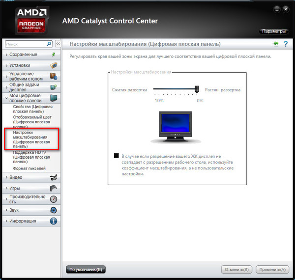 It supports Windows 10, 8, 7, Vista, XP, 2016 server, 2012 server, 2008 server, and 2003 server. The processors it supports are Intel, AMD, and VIA x86.
NZXT CAM
NZXT CAM is best for monitoring your gaming PC CPU temperature. It can manage temperature, devices, and performance from a single app. It is an efficient, easy-to-use, and fast application that gives you access to control everything on the computer.
NZXT CAM allows you to see what is going on inside your computer, from the processor’s load to bandwidth consumption. You can also see the work of applications on every machine and quickly track the issues to enhance the performance of your computer.
When you are in a game, track temperatures, bandwidth, FPS, and more with a super stable and low-impact in-game overlay. NZXT CAM supports time played, current FPS, GPU/CPU temperature, battery level, GPU/CPU load, and many more.
It offers a beautiful and intuitive interface from which you can control fan speeds, PSU voltages, case lights, and more.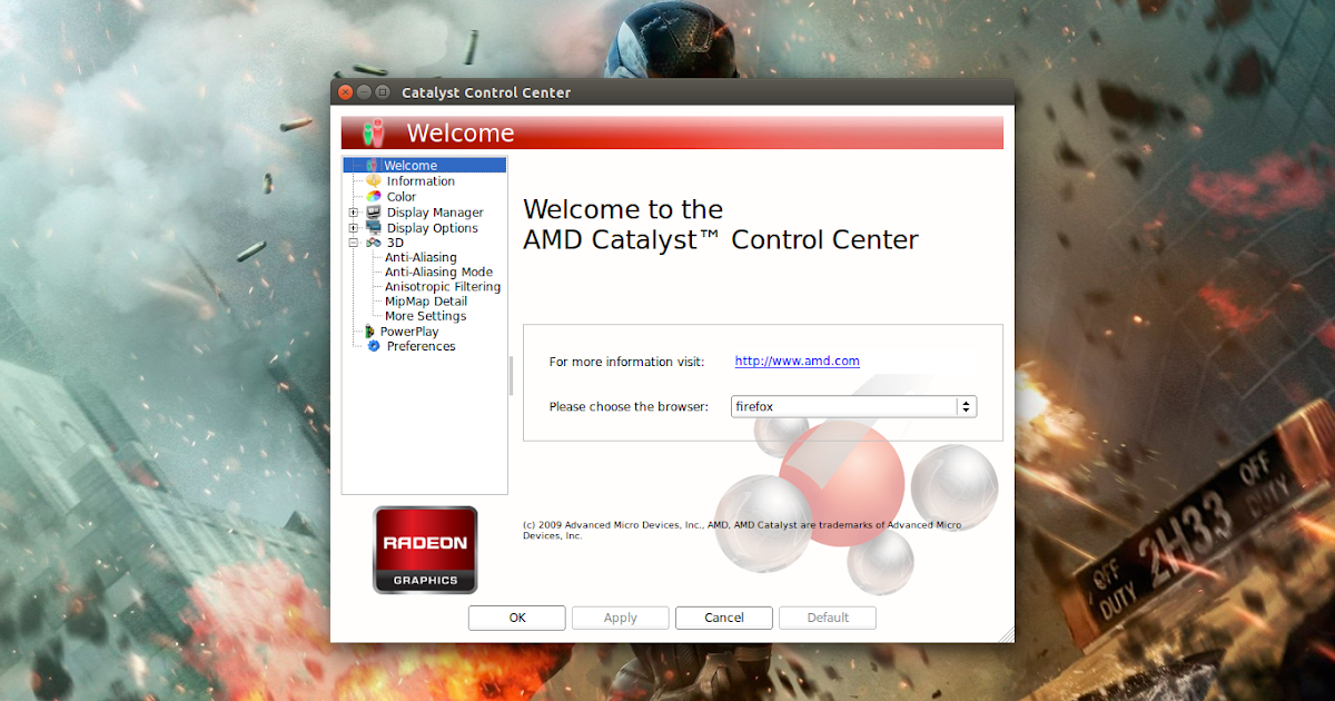 Download the next-gen CAM software and start checking the CPU temperature.
Speccy
Need to find out why your computer is so hot?
Speccy has the information you want to know. It is a lightweight, advanced system, and fast information tool for the computer. Speccy is a place where you can get a quick summary of the result, or you can dive deeper into your PC’s hardware to make purchasing and upgrading decisions.
In a single interface, you will find every detail so that you can save your time getting stats like motherboard, CPU, graphics cards, RAM, and more. Become a pro in solving problems before they happen by seeing the temperatures of the critical components.
It gives you access to save your results as an XML, text file, or snapshot to share them easily. Check the specs of your computer and see whether it needs diagnosis for any issues. The tool helps you boost the performance of PCs without upgrading their hardware. Download the free version to get advanced PC insights or buy the tool to get more features.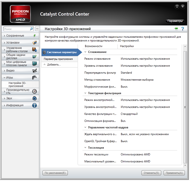
Open Hardware Monitor
Open Hardware Monitor is open-source software that monitors the fan speeds, load, clock speeds, voltages, and temperature sensors of a computer. It supports many hardware monitoring chips that are found on mainboards.
The tool reads the core temperature sensors of AMD and Intel processors to check the CPU temperature. It also displays sensors of Nvidia and ATI video cards along with SMART, hard drive temperature.
You can see the values on the main window in the system tray and on a customizable desktop gadget. Open Hardware Monitor runs on 64-bit and 32-bit Microsoft Windows XP, Vista, 7, 8, 8.1, 10, and x86-based Linux OS without installation.
In addition, it comes up with new features and bug fixes. It can now detect ITE IT8655E, IT8686E, and IT8665E super I/O chips and improves its AMD GPU support, AMD GPU, and CPU labels. It also enhances the Nuvoton NCT679XD super I/O RPM calculation for fans.
The tool runs Microsoft Windows along with the . NET framework of version 4.5. Download the Zip file of the software, unzip it to install, and start monitoring.
HWMonitor
Do you need to monitor the temperatures, fan speed, and voltages of your computer?
Try HWMonitor – a hardware monitoring program that allows it to read PC system’s health sensors. It handles standard sensor chips like Winbond ICs, ITE IT87 series, and others. It can read video card GPU temperature, CPUs on the die core thermal sensors, and hard drive temperature through SMART.
HWMonitor supports Intel Alder Lake, DDR5 memory, and the Z6xx platform and uses the latest version 1.44 for Windows with AMD Ryzen 5300G, 5300G, and 5600G APUs. It also supports AMD Radeon RX 6700 XT and 6900 XT GPUs.
In the new release, it adds GDDR6 and hotspot temperatures on the NVIDIA GPUs. It works on both 32-bit and 64-bit versions. You can download a .exe file for setup or a .zip file to unzip and install it on your computer.
HWiNFO is a diagnostic and professional system information software system for operations like hardware analysis, reporting, and monitoring for DOS and Windows.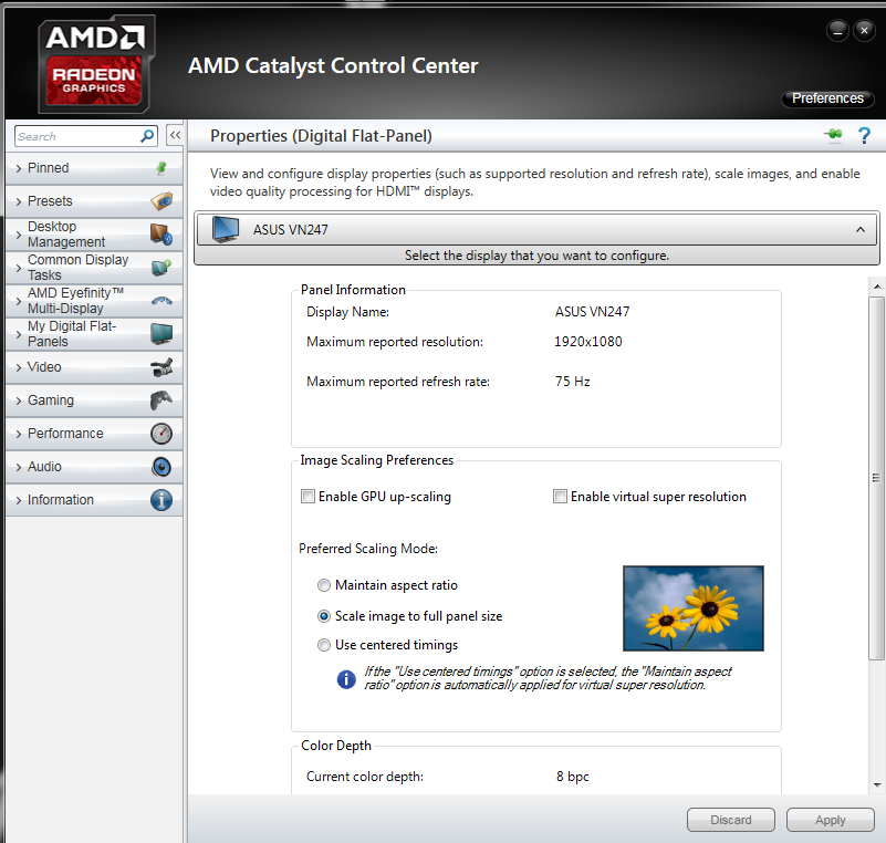
Always get in-depth information on the hardware with the latest standards and technologies. Also, monitor the system components accurately for failure prediction and actual status and customize the interface using various options.
Access extensive reporting through multiple reports, interfacing with different add-ons and tools, and status logging. It supports the AMD and Intel family of processors, graphics cards, and chipsets. In addition, it helps find overload, performance loss, and overheating.
The tool also monitors various hardware and system parameters covering GPUs, CPUs, peripherals, drives, motherboards, etc. You can export the result into CSV, HTML, and XML reports. Moreover, it will also show various shapes like tables, OSD, tray icons, etc., to display the result. Download the software and start analyzing what is happening inside your PC.
AIDA64
Are you searching for an industry-leading diagnostic, benchmarking, and system information solution for engineers and corporate IT technicians?
Go for AIDA64. It has a hardware detection engine that provides in-detail information about the software and offers diagnostic support and functions for overclocking. It also monitors the sensors to gather accurate temperature, fan speed, and voltage readings, while the diagnostic function helps detect and prevent hardware issues.
The tool offers benchmarks for measuring each hardware performance and the whole system. Also, AIDA64 Engineer is compatible with 32-bit and 64-bit Windows editions, including Windows Server 2019 and Windows 10.
You will get more than fifty pages of information on the hardware configuration, installed programs, security applications, Windows settings, and software licenses. It performs system stability tests by using a multi-threaded stress module. It also includes a hard disk, OpenCL GPGPU, and SSD video adapter stress testing and gives accurate results all the time.
SensorPanel helps build the custom panel that perfectly suits the design to monitor all the sensors, utilization, cooling system, and many more.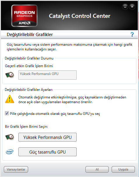 The latest release supports VFD and LCD screens and monitors sensor values remotely on tablets and laptops.
AIDA64 displays the measured values on the OSD panel, Desktop gadget, Razer SwitchBlade LCD, Logitech G15/G19 Gaming Keyboard LCD, and System Tray icons. For this, you require Intel Pentium or later processors, 80 MB of free space, and Windows operating system.
The software is available for $199.90.
Bonus tips to keep CPU healthy
- Clean your computer system frequently, including its fans and the room where it is placed, to make sure there is no dust inside to increase the CPU temperature
- Keep the computer away from windows or vents that can attract dust particles.
- Perform regular malware scans so that no build happens in your computer in terms of malware, viruses, worms, Trojan horses, etc.
- Keeping drivers up-to-date is essential to keep them running at optimal performance.
- Remove obstacles restricting the airflow from your computer
- Be cautious when overclocking the CPU
- Add more cooling fans if possible
- Upgrade CPU fans if the one in use malfunctions
- Apply liquid cooling if you use your computer for video gaming or other intensive uses.
Conclusion
Excessive temperature can do severe harm to your computer. It may be due to dust, viruses, using high-end video games, or other intensive tasks. Whatever the case, take care of your computer and prevent its CPU from getting heated with the help of the best CPU temperature monitoring tool and improve its performance, lifespan, and reliability.
11 Best CPU Temperature Monitors For 2022 (Paid & Free Software)
We are funded by our readers and may receive a commission when you buy using links on our site.
How hot is your computer? If your employees are noticing machines slowing down or failing then overheating could be the reason why. We show you the best CPU load & temperature monitors to help you stay on top of failing hardware on your network.
Tim Keary
Network administration expert
UPDATED: January 28, 2022
All PCs and servers on your network emit heat but there is a limit to the amount of heat a computer can withstand before damage is done to hardware.
CPU temperature monitors enable you to monitor CPU temperature from one location. Monitoring the temperature allows you to identify when hardware devices are overheating and gives you a chance to fix the problem before any damage is done to the device – which is vitally important for network troubleshooting.
Here is our list of the eleven Best CPU Load & Temperature Monitor tools:
- SolarWinds CPU Load Monitor EDITOR’S CHOICE Part of the Engineer’s Toolset, this monitoring tool spots when a server is being overused. Excessive use can lead to high CPU temperatures and alerts in the monitor trigger alarms when activity gets too intense. Start a 14-day free trial.
- Paessler CPU Monitoring with PRTG (FREE TRIAL) This all-in-one infrastructure monitor includes several sensors that accurately measure server temperature, either through SNMP or through WMI.
- Site24x7 Infrastructure This package of monitoring systems covers servers, networks, cloud services, and logs.
 It is a SaaS platform that will give you a constant CPU load readout for each of your servers.
 - HWMonitor A hardware monitoring tool with temperature and fan speed monitoring. It is compatible with sensor chips including the ITE IT87 series and Winbond ICs.
- Open Hardware Monitor An open-source hardware monitoring platform. It monitors temperature sensors, fan speeds, voltages, load, and clock speeds.
- Core Temp Temperature mentor that takes system information from the Digital Thermal Sensor (DTS) of computer processors. It has a Core Temp Monitor app for Windows and Android phones.
- HWiNFO Free hardware and temperature monitoring tool. The tool comes with real-time monitoring capabilities and a customizable alert system.
- Atera A cloud-based remote monitoring and management platform that includes device and server monitoring for a range of metrics, such as CPU metrics.
- SpeedFan A piece of software that monitors the voltage, fan speed, and temperature of computers.
 It also allows the user to control fan speeds and reduce noise.
 - AIDA64 Extreme Hardware monitor with support for over 250 different types of sensors that can monitor temperature, voltage, fan speed, and power. It is available for all 32-bit and 64-bit versions of Windows.
- Rainmeter Top CPU temperature monitor for Windows devices that monitors core temperatures, CPU, disk usage, and RAM. It includes customizable skins that you can use to build a unique monitoring environment.
The Best CPU Temperature Monitor Software
Our methodology for selecting a CPU temperature monitor
In this section we review the best CPU load & temperature monitors to help you stay on top of failing hardware on your network. We analyzed the following features of each tool:
- Includes temperature read-outs per core
- Identifies motherboard temperature
- Includes thresholds on CPU temperature and a connected alert mechanism
- Can also monitor fan speed and status
- Additionally monitors processor activity
- Shows the CPU clock speed
- Allows a free period for assessment
- Offers good value for money with respect to the number of functions the software provides
1.
 SolarWinds CPU Load Monitor EDITOR’S CHOICE
The SolarWinds CPU Load Monitor is part of the Engineer’s Toolset, which is a bundle of more than 60 monitoring and entire system management utilities. The CPU Load Monitor can track the performance of network devices and watch to make sure their hardware doesn’t get overloaded.
Key Features:
- Autodiscovery
- Spots capacity issues
- Live reports
- Alerts
- Notifications by email or SMS
Network devices rarely include mechanisms to measure temperature. So, there just isn’t a temperature metric to pick up from switches or routers. However, heat is usually only generated by these devices when they get overworked and the electronic elements that will create heat when overloaded are the CPU and the interfaces. The CPU Load Monitor measures these components and tracks their activity live in the Engineer’s Toolset’s dashboard.
The CPU Load Monitor starts its service by searching the network for all connected devices and lists them in an inventory.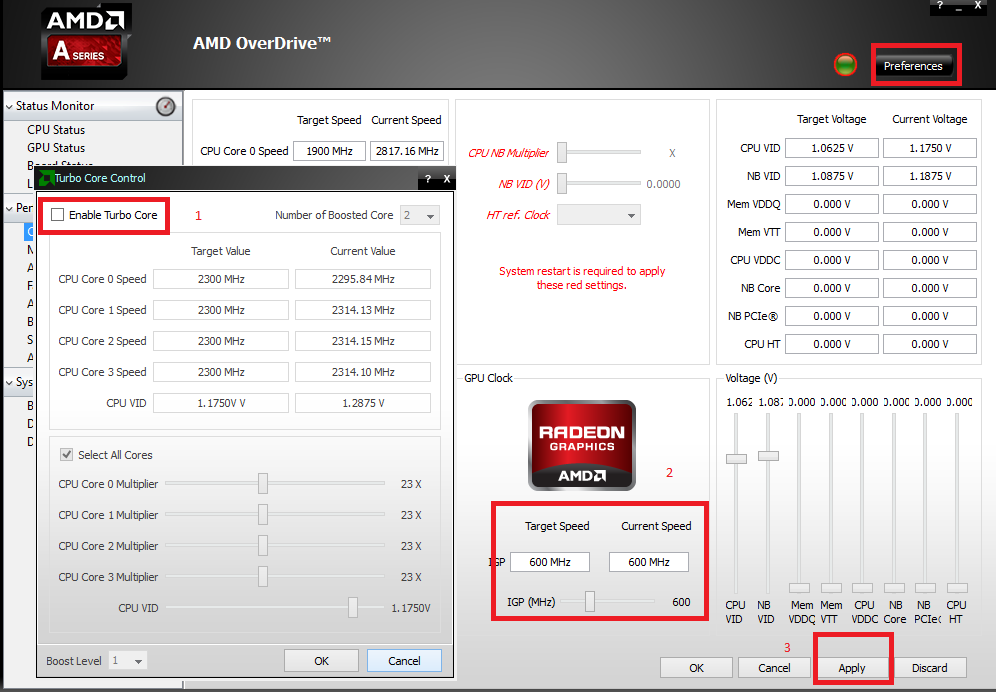 Once that autodiscovery phase has been completed, each listed device will automatically be monitored and one of the tracked factors in the CPU load. The CPU load monitor also records interface statistics and memory utilization, so all of the elements inside a network device that could overheat are watched by the CPU Load Monitor.
The monitor automatically sets threshold levels on all of the performance statuses that it tracks. These can be adjusted manually. When a threshold is crossed, the CPU Load Monitor generates an alert. This alert is shown on the dashboard and is also sent out to key personnel as an email or SMS message. This facility means that technicians don’t have to sit watching the panel always for signs of overheating. The threshold levels should be set so that the warning gives staff enough time to take preventative measures before any physical damage or performance impairment occurs.
Pros:
- Utilizes simple yet effective alarms for long term proactive CPU temperature monitoring
- Part of a larger toolset specifically designed network admins and IT technicians that contains tons of additional troubleshooting tools
- Alerts can be set to email, SMS, or webhook to fit into virtually any alerting platform
- Uses autodiscovery to find new devices on a network automatically
- Can accurately measure the temperature of PC, server, or server host
Cons:
- Would like to see a longer trial period to test all of the tools
The Engineer’s Toolset, including the CPU Load Monitor, is available from SolarWinds on a 14-day free trial.
EDITOR’S CHOICE
The CPU Load Monitor is part of the Engineer’s Toolset, a one-stop-shop for all network troubleshooting needs. You can monitor multiple routers concurrently and set warnings and alarm thresholds with ease. One of the best options available today..
Download: Get 14-day Free Trial
solarwinds.com/engineers-toolset/use-cases/cpu-monitor: solarwinds.com/engineers-toolset/
OS: Windows
2. Paessler CPU Monitoring with PRTG (FREE TRIAL)
Paessler PRTG is an all-in-one infrastructure monitor that covers networks, servers, and applications. When looking for a temperature monitor, there are several different systems that you could choose. The PRTG service is a bundle of sensors and every customer gets shipped the full set. When starting up the software, the systems device manager has to decide which sensors to turn on and so is able to tailor the system to adjust the necessary monitors.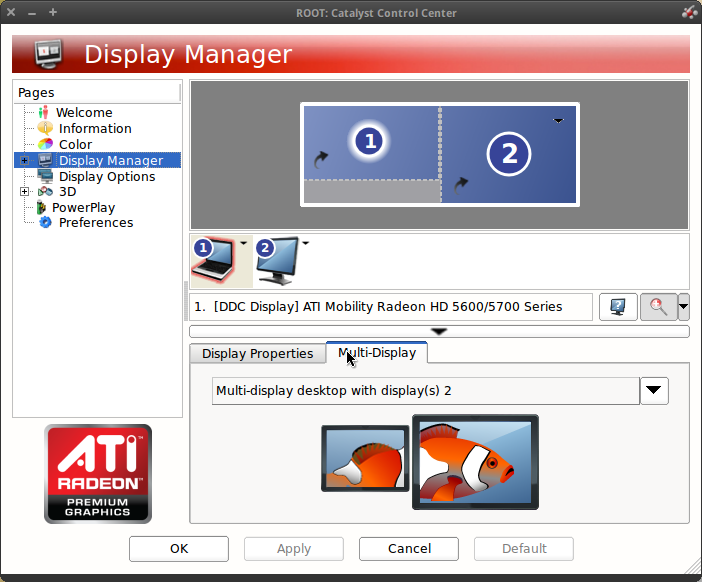
Key Features:
- SNMP manager
- Reports on device conditions
- Uses WMI
- Live device load tracking
The PRTG package of sensors includes several monitors that can pick up temperature information either from servers or network devices. Temperature performance is one of the factors that can be reported through SNMP and PRTG has a sensor for that. However, not every hardware provider implements procedures to report on temperature by that method.
PRTG includes monitors that pick up CPU performance data on Windows servers through WMI. A sensor for Linux servers also monitors CPU performance managed by that operating system. PRTG has a total of nine different sensors that are capable of looking for temperature information gathered on servers and network devices. If none of your equipment has an actual thermometer inside, there is no way for any system monitor to collect temperature information. However, in those cases, monitoring CPU load on all devices acts as a proxy statistic for temperature statuses.
Pros:
- Allows admins to scale their monitoring efforts easily using the PRTG ecosystem
- Can be configured to measure only temperature, and then easily modified to expand that scope
- Pricing is based on the number of sensors, giving it scalability and flexibility for any size network
- Features a number of pre-configured sensors that are ready to use out-of-box
- Allows users to build their own sensors based on their individual needs
- Uses CPU load monitoring for devices without thermometers
Cons:
- Is a feature-rich platform so be prepared for a learning curve
Paessler makes PRTG available on a 30-day free trial. This is the full version of the monitoring system and you can activate all of the sensors you want during the trial period
Paessler CPU Monitoring with PRTG
Download 30-day FREE Trial
Read More: Best Hardware Monitoring Tools
3.
 Site24x7
Site24x7 is a cloud platform that offers bundles of monitoring services for both on-premises and cloud resources. The Infrastructure package includes network, server, cloud resources, and log monitoring. One of the key metrics that the server monitoring section of this tool tracks is CPU utilization.
Key Features:
- Delivered from the cloud
- Monitors physical and virtual systems
- Centralizes supervision of multiple sites
This package is able to monitor servers running Windows, Windows Server, or Linux (SUSE, Debian, and CentOS). The service can also monitor the CPU load for Docker, Kubernetes, Hyper-V, and VMWare implementations.
A great benefit of this package is that it enables you to monitor all of your resources with one subscription.
Pros:
- Bundles together a range of system monitors
- A great option for small businesses
- No need to run any software on your premises to get this monitoring service
Cons:
- The low teaser rate doesn’t offer much capacity – large businesses will pay much more
The bundling of a range of monitoring services into one package is a great deal for small businesses because this ends up costing a lot less than buying separate monitoring systems for networks, logs, and servers..png) These are industry-leading tools that big businesses use. The Server monitor shows CPU utilization as standard but all dashboards can be customized. Access a 30-day free trial of Site24x7 Infrastructure.
These are industry-leading tools that big businesses use. The Server monitor shows CPU utilization as standard but all dashboards can be customized. Access a 30-day free trial of Site24x7 Infrastructure.
4. HWMonitor
HWMonitor is a hardware monitoring tool for Windows that monitors computer temperatures, voltages, and fans. The software monitors the hard drive and video card GPU temperature. These metrics give you a strong indication of the overall health of a device.
Key Features:
- Temperature, fan, and voltage monitors
- Free version
- Low CPU usage
There is also an extended version of HWMonitor called HWMonitor PRO, which costs $22.10 (£17.08) for 10 remote connections or $38.71 (£29.92) for up to 20 remote connections. HWMonitor Pro adds remote monitoring, graph generation, and an improved user interface.
Pros:
- Freeware, with paid options for remote monitoring
- A great option for home labs and smaller networks
- Available for both Linux and Windows
Cons:
- Interface isn’t customizable making it difficult to track only the metrics you want
- Could use better visualization features when reporting over longer periods of time
When using the PRO version you can monitor multiple PCs in a list view. Next to each device you can view the Value, Min, and Max temperatures of hardware components. The list perspective makes it easier to monitor multiple devices at once. You can download the program for free.
5. Open Hardware Monitor
Open Hardware Monitor is an open-source hardware monitoring solution that monitors the temperature, fan speed, load, voltage, and clock speed of computers. The tool supports common hardware chips meaning it can be deployed in a range of environments. The user interface displays the data pulled from temperature sensors in a list format – making it easy to find mission-critical devices and maintain them.
Key Features:
- Free to use
- Monitors temperature, voltage, clock speed, and fan speed
- Runs on Windows and Linux
Open Hardware Monitor is recommended for those users who want to use a low-cost, open-source temperature monitoring platform. Open Hardware Monitor is available for Windows XP, Vista, 7, 8, 8.1, 10, and Linux. You can download the program for free.
Pros:
- Is a free open-source transparent project
- Can measure other metrics like fan speed, clock speed, and voltage alongside temperature readings
- Better suited for home PCs and enthusiasts
Cons:
- Only available for Windows
- No management console, cannot monitor multiple machines at the same
- Not ideal for a business environment
6.
 Core Temp
Core Temp is a temperature monitoring tool that can monitor Intel processors, AMD, and VIAprocessors in real-time. The program uses data taken from the Digital Thermal Sensor(DTS) of each processing core. The software collects the data and then displays it on the screen so the user can take an accurate temperature reading.
Key Features:
- Focused on temperature
- Reports metrics measured by the core
- Extensible
There are multiple add-ons available for Core Temp so the user can add additional capabilities. For example, the Core Temp Monitor app allows users to monitor devices on Windows and Android phones. The Core Temp Grapher plug-in creates a visual display that creates a graph for each processor core showing load percentage and core temperature.
Pros:
- Supports an Android and iPhone app for remote monitoring
- Is completely free for personal use
- Barebones interface makes the tool very lightweight and resource conservative
Cons:
- Relies on a plugin for additional functionality for visuals, would like to see this built into the product itself
- Great for home use, but not detailed enough to support a large network
- Lack alerting features
Core Temp is available for Windows XP, Vista, 7, 8,10, 2003 Server, 2008 Server, 2012 Server, and 2016 Server. For commercial use, you have to purchase a commercial license. You can request a quote from the company directly. Download Core Temp for free.
7. HWiNFO
HWiNFO is a real-time system and temperature monitoring solution for Windows. With HWiNFO you can monitor hardware elements like CPUs, GPUs, drives, mainboards, and more to discover performance issues. The user interface is easy to navigate and you can view in-depth performance data by clicking through the infrastructure hierarchy.
Key Features:
- Free to use
- Always on
- Provides a Desktop sidebar
Customizable alerts help to keep track of overheating and performance degradation. There are also add-ons you can use to augment the monitoring experience. For instance, the HWiNFOMonitor plugin adds a customizable sidebar which displays CPU performance with bars and graphs.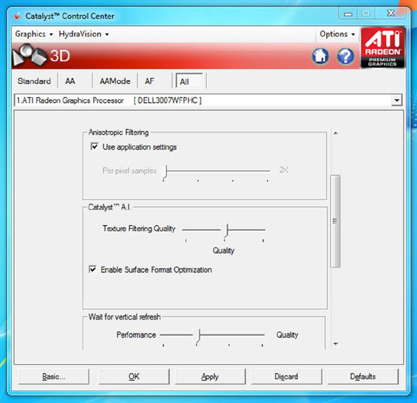
Pros:
- Extremely detailed, includes metrics not found in other tools like cache sizes, ratio, clocks speed per core, and timing information
- Can track other metrics such as GPU and disk utilization
- Is fully customizable
- Offers built-in visualizations
Cons:
- Cluttered interface makes it difficult to track metrics on devices with many parts like servers or hosts
- Only available for Windows
- Not for non-technical users
- Lack proactive features like robust alerting options and inventory management\
HWiNFO is ideal for enterprises that require a free CPU monitoring solution. The tool is available HWiNFO32 for Windows 32-bit and HWiNFO64 for Windows 64-bit. You can download the program for free.
Read more: Step-By-Step CPU Benchmark Test
8. Atera
Atera is a cloud-based platform that includes all of the software that a managed service provider (MSP) needs to run its business.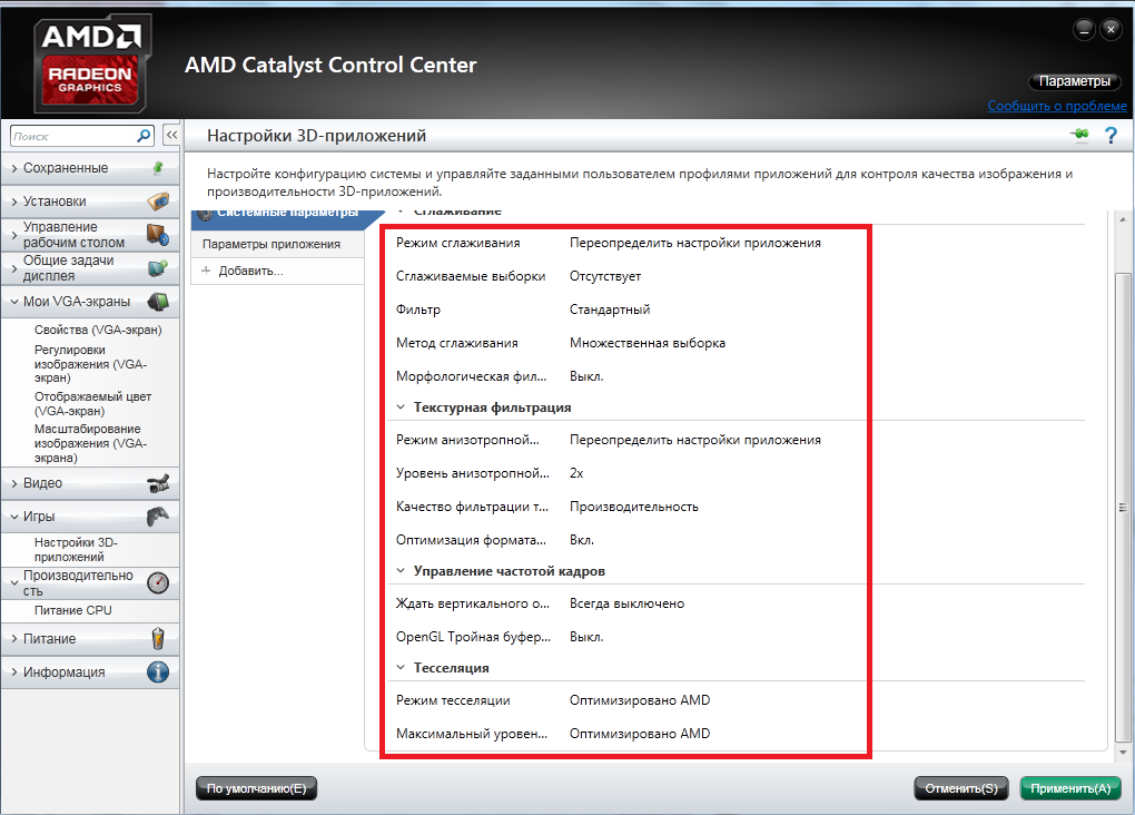 The remote monitoring and management (RMM) module of the system includes monitoring screens for networks, servers, endpoints, and applications.
Key Features:
- Designed for MSPs
- Monitors multiple sites
- Tracks device capacity utilization
The home screen of the monitoring dashboard gives a system overview. Atera employs an alert-based system that notifies an administrator if there is anything wrong on the monitored system. So, it is easy to spot problems at a glance. From the summary screen, the operator can click through to see details of individual pieces of equipment.
The device, endpoint, or server monitoring screens include a range of statuses, including CPU performance data. These categories of feedback are all live and they include CPU temperature, utilization, and capacity. Other factors shown in the screen include fan performance, memory usage, disk activity, and I/O throughput rates.
Pros:
- Lightweight cloud-based monitoring application
- MSP/reseller focused, making this a great option to provide temperature readouts as a part of your service offering
- Offers some of the best visual dashboards and reporting capabilities compared to its competitors
- Can also list disk I/O, memory usage, fan speeds, disk capacity, ect, making this a more holistic tool for device health monitoring
- Product is a subscription service, making it affordable for any size network
Cons:
- Atera is an in-depth all-in-one product, it could take time to learn all of its feature and options
Atera is a subscription service with a rate per technician per month.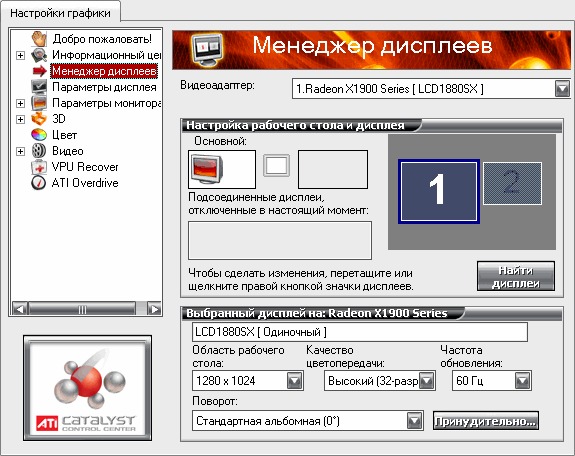 The cloud-based dashboard is accessed through any standard browser, so you don’t need to host the Atera software on-premises. You can get a free trial to experience the platform for yourself.
9. SpeedFan
SpeedFan is a hardware monitor that monitors: temperature, fan speed, voltage, and hard disk temperatures. The software can also display S.M.A.R.T data from hard disks. With SpeedFan you can configure the program to change fan speeds remotely according to the system temperatures. For example, you can choose a minimum and maximum fan speed.
Key Features:
- Temperatures, voltage, and fan speed
- CPU and disk monitoring
- Free to use
The user interface is simple to use, and the platform automatically detects temperature sensors so you don’t need to waste time creating extensive configurations. However, if you want to engage with more complex configurations you can do so on the Advanced page. Here you can offset inaccurate temperature readings and control fan speed.
Similarly, if you want to view visual displays then you can do so through the Charts window. The Charts window displays performance charts that allow you to choose what metrics you want to monitor. Simply enter the start and end time of your reading, what elements you want to monitor, and the values you want to see.
Pros:
- Simple installation that begins pulling metrics immediately
- Built for individual machine monitoring with a simple interface
- Collects S.M.A.R.T data as well as detailed metrics about the status of your machine’s fans
- Helps users correlate fans speed with temperature
Cons:
- Not for larger networks
- Lacks long term monitoring features
- Reporting features could use improvement
SpeedFan is available for Windows 9x, ME, NT, 2000, 2003, XP, Vista, Windows 7, 2008, Windows 8, Windows 10, and 2012.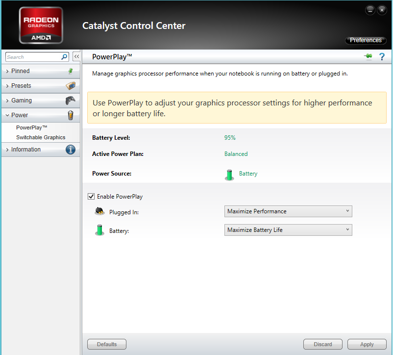 You can download the tool for free.
10. AIDA64 Extreme
AIDA64 Extreme is a device monitor that monitors temperature, voltage, fan speeds, and power. AIDA64 supports over 250 different types of sensors meaning it works with most IT assets. The user interface is simple with a SensorPanel where you can build a custom panel to monitor temperature data and other information.
Key Features:
- Customizable dashboard
- Extensive device monitoring capabilities
- Version available for 32-bit systems
One feature that is particularly useful for enterprise users is external display support. You can view hardware data on over 50 external LCD/VFD screens, including smartphones and tablets. Display support makes sure that you can see all of the information that you need.
Pros:
- Monitors temperature as well as virtually all aspects of a devices performance and hardware specifications
- Designed for technicians, outputs very detailed measurements and incredibly detailed with over 250 sensors
- Supports external displays, ideal for network operation centers, or smartphone apps
Cons:
- Only available for Windows
- Licensing is marketed towards smaller networks, not enterprise companies
- Interface can feel overwhelming without customization
- Would like to see better alerting features with more options
AIDA64 Extreme is available for all 32-bit and 64-bit versions of Windows.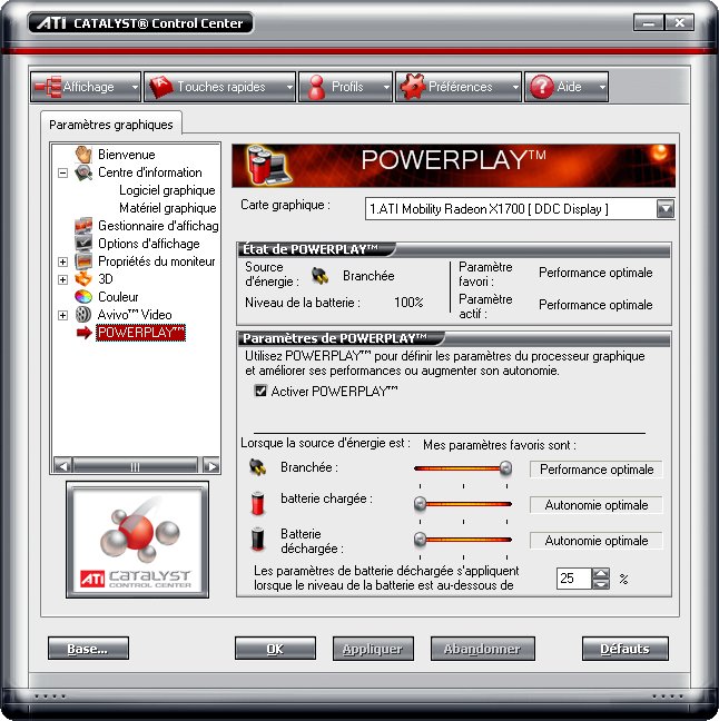 The tool is useful for users who want a low maintenance temperature monitor. You can purchase AIDA64 Extreme for home users from $39.95 (£30.87) for three PCs. You can download the 30-day free trial.
11. Rainmeter
Rainmeter is a free, open-source CPU temp monitor for Windows. Rainmeter can monitor data on temperature, CPU, RAM, disk usage, and more. There is a range of skins that make this possible. Skins are essentially small tools that you can customize the layout of. The user can create monitoring skins, use one of the starter packs or install a plugin.
Key Features:
- Attractive interface
- Free to use
- Reports on resource utilization and temperature
For example, the CoreTemp plugin allows the user to pull information from the CoreTemp application. The advantage of doing this is that you can use skins to control how you see information on the screen.
Skins are drag-and-drop so you can create a custom monitoring panel for better visibility. You can also use one of the starter skins so you don’t have to create any if you don’t want to.
Pros:
- Sleek minimalist design is both lightweight and nice to look at
- Completely free, open-source, and transparent
- Track temperature, CPU, RAM, and disk metrics
- Can apply custom skins via plugin or pre-made start pack
- Uses drag and drop menus to customize your dashboard
Cons:
- Marketed towards hobbyist and home users, not the best option for larger networks
- Great for non-technical users, but lacks detailed metrics
- Lacks a robust reporting feature for long term monitoring
- Lacks device management capabilities for bigger networks
If you’re looking for a customizable tool that’s accessible for non-technical users then Rainmeter is an excellent choice.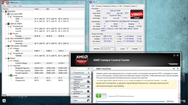 Rainmeter is available from Windows 7 to Windows 10. It’s available as a free download.
Which CPU monitoring software works on Windows?
| Name | Platform | Price |
|---|---|---|
| SolarWinds CPU Load Monitor | Windows | Free trial |
| HWMonitor | Windows | Free version available |
| Open Hardware Monitor | Windows, Linux | Free |
| Core Temp | Windows | Free |
| Paessler CPU Monitoring with PRTG | Windows, Linux, Mac | Free trial |
| HWiNFO | Windows | Free |
| SpeedFan | Windows | Free |
| AIDA64 Extreme | Windows | Free trial |
| Rainmeter | Windows | Free |
CPU Load & Temperature Monitors: Stop Your Devices from Overheating
CPU temperature monitors make it easier to monitor the heat of an entire network of devices. SolarWinds CPU Load Monitor (with ETS), Atera, PRTG, HWMonitor, and Open Hardware Monitor are all reliable solutions for monitoring CPU performance. Implementing regular hardware monitoring with CPU monitors will make sure your devices stay available year-round.
CPU Temperature Monitors FAQs
How do I see CPU temp on my desktop?
There isn’t a CPU temperature monitor in your operating system. In order to get information about CPU temperature, you would have to go down to the BIOS. It is much easier to install a monitoring tool. We recommend the SolarWinds CPU Load Monitor to check on heat-generating activities or the HWMonitor, which interprets BIOS data in a GUI interface.
Why is my CPU temperature 70 degrees on an idle laptop?
A CPU temperature of 70 degrees Celsius is normal when the computer is very active. However, when idle, the CPU’s temperature should be around 45 degrees. A high temperature implies that the CPU is not really idle, but has a heavy workload put on it by background tasks and services. If the CPU monitor shows that this is not the case, then the high temperature could be a sign of a broken fan.
How do I check my CPU usage?
In Windows, CPU usage is displayed as a live metric in the Task Manager.
- Right-click on the Task Bar at the bottom of the screen and select Task Manager from the pop-up menu.
- Wait for the Task Manager to open and then click con the Performance tab.
- Click on CPU at the top of the left-hand options list to see a live graph of CPU performance.
How do I monitor my GPU temperature?
If you have a graphics processing unit in your computer, you can see its temperature in the Task Manager of Windows 10.
- Right-click on the taskbar and click on Task Manager in the popup menu.
- When the Task Manager opens, click on the Performance tab.
- Scroll down the left-hand menu to find GPU.
 The mini display there includes the GPU temperature in Celsius.
What CPU temperature is too high?
There are many factors to be taken into account when working out what is an acceptable CPU temperature. However, as a rule of thumb, for an Intel processor, a temperature of more than 40 degrees Celsius when it is inactive is worrying and a temperature of more than 85 degrees Celsius when it is under full load is a cause for concern.
What is a normal CPU temperature at full load?
For Intel processors, generally, the normal CPU temperature at full load is between 50 and 60 degrees Celsius. Intel Celeron processors run hotter at about 65 to 80 degrees Celsius under full load. AMD processors don’t have as much variability per model as Intel processors. They shouldn’t go above 70 degrees Celsius under full load.
What do I do if I don’t get a CPU temperature reading?
If you are using a temperature monitor and it doesn’t give you a reading, the chances are that the program you chose is not compatible with the status output mechanism of your CPU temperature gauge.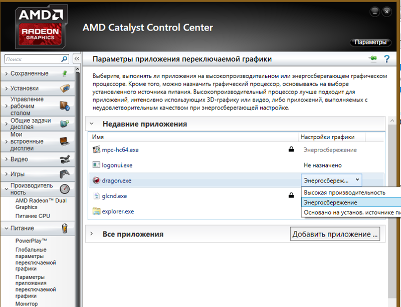 Picking a different temperature monitoring package might solve the problem.
Can CPU temperature be wrong?
There are a number of factors in the chain of activity that goes into temperature reporting and if one of them is faulty, you will get an incorrect report, so CPU temperature monitoring can go wrong. To work out whether the temperature monitor is giving incorrect reports, look for illogical results. For example, if your CPU registers no activity and the fan is working properly but the monitor says that the temperature is high, the monitor is probably wrong.
Related post: CPU Monitoring Guide & Tools
How To Monitor Your GPU Temperature [2022 Guide]
Your GPU temperature getting too high can signify more serious problems developing under the hood.
Therefore, it’s crucial to keep that in check, especially when your GPU is under a lot of strain, for example, when running resource-heavy games. Here’s how to monitor your GPU temperature.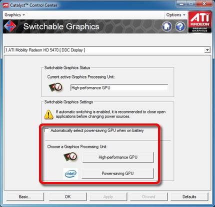
Table of ContentsShow
Why Is It Important To Monitor Your GPU Temperature?
There are different reasons why you might need to monitor your GPU temperature, but they all boil down to the same old goal: getting the best performance.
Overclocking
If you have tried overclocking your GPU, you will need to keep a close eye on the temperature that your graphics card’s slightly increased clock is producing. Keeping the temperature of the GPU in that sweet spot is necessary when overclocking.
Today, graphics card manufacturers are well aware of the overclocking community among gamers. This has led to them carefully designing their graphics cards to accommodate overclocking while keeping their product’s integrity intact.
A key thing you will need to consider when overclocking your GPU is the possible need for additional cooling.
This is the key to keeping your GPU running at an optimal temperature.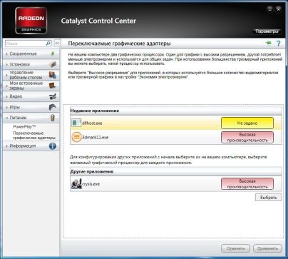 If you’re experiencing overheating, this is probably the first thing you should consider to fix the problem.
Playing Resource-Heavy Games
Even if you’re playing a game with higher-quality graphics for a longer period of time, it could place a strain on the GPU. This, in turn, can lead to more severe problems.
The key here is knowing how well your graphics card can handle the load. In many situations, your GPU will fulfill the minimum system requirements or even recommended system requirements but might still have trouble running the game at higher graphical settings for a few hours.
Depending on how long you ignore the obvious problems while playing (such as stuttering or beeping from inside the PC case), you could end up with different levels of damage. Fortunately, most modern GPUs are built in a way that prevents the graphics card from suffering physical damage by turning it off before things get too heated.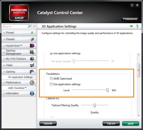
On the other hand, that doesn’t stop other related hardware from malfunctioning. Also, the GPU shutting off when hitting dangerous temperatures doesn’t completely prevent it from being damaged. Ignoring the problem and having the GPU shut off multiple times can eventually wreck the card and leave you looking for a replacement.
Best Ways To Monitor Your GPU Temperature
As mentioned earlier, an overheating GPU can cause some serious issues. Fortunately, there are multiple ways to keep an eye on the GPU temperature and ensure that it doesn’t cross that dangerous threshold.
Each of these options has its pros and cons, and we hope to teach you these well enough to make an informed decision.
Manufacturer-Specific Software
Both AMD and NVIDIA have companion software for their graphics cards. This is mostly used for tasks such as keeping your drivers up to date and enabling additional performance-enhancing features specific to the respective brand.
Both NVIDIA and AMD have bundled an overclocking tool together with the drivers (you will need GeForce Experience for NVIDIA GPUs).
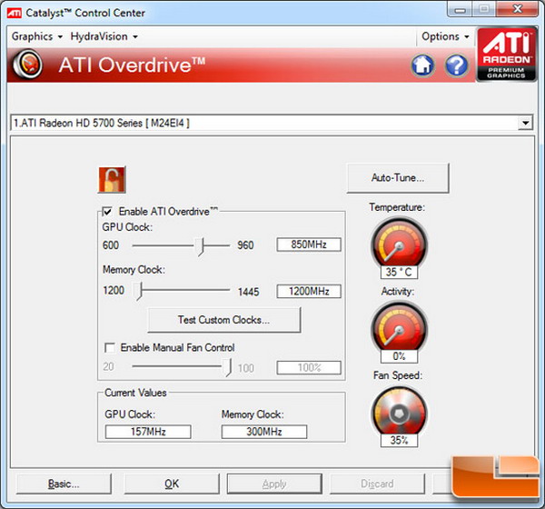
AMD’s solution allows the user to adjust the fan speeds, clock speeds, and power delivery. There is also the option for automatic overclocking.
NVIDIA was a bit late to the party, and their OC tool still isn’t as good as AMD’s. There is an “Automatic Tuning” option to overclock the GPU clock speeds automatically, but there’s no option to do it yourself.
As both companies have delivered some kind of overclocking tool with their drivers, they have also added a feature for performance monitoring.
Performance Monitoring on AMD cards
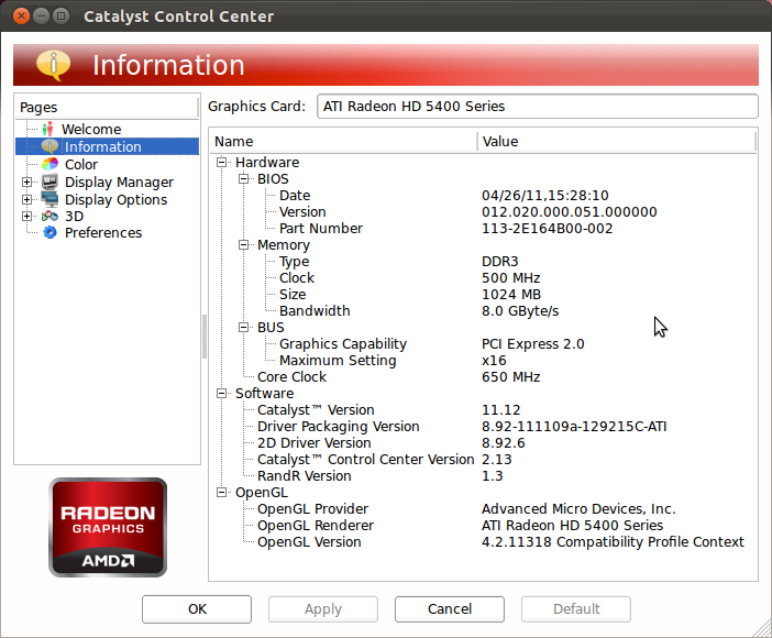
Both monitoring tools deliver plenty of information, including fan RPM, memory clock, GPU clock, temperature, etc. If you need even more data, you should consider third-party software.
Third-Party Solutions
With technological developments, there were unsurprisingly many enthusiastic people willing to learn all the ins and outs of how a PC works. Thanks to those people, we first saw component monitoring software, some of which are still in use today.
Disclaimer: Most of these tools will include other functions, enabling you to monitor other parts of your PC, which is always a plus.
HWiNFO
HWiNFO has to be the best of the bunch, considering you can get temperature readings on almost every component in your computer. This includes everything from your GPU to your drives.
Additionally, there is an option to oversee clock speeds, voltage, and even your RAM timings. It is also customizable, so you can easily remove the sensors you aren’t interested in.
That’s not all. Add-ons are also available for HWiNFO, for example, an add-on to use Riva Tuner’s, MSI Afterburner’s, or EVGA Precision’s On-Screen Display tool. There are many more add-ons for extra information and features.
Download HWinfo
Open Hardware Monitor
This tool is another old-school-looking piece of software but is just as reliable as the first one.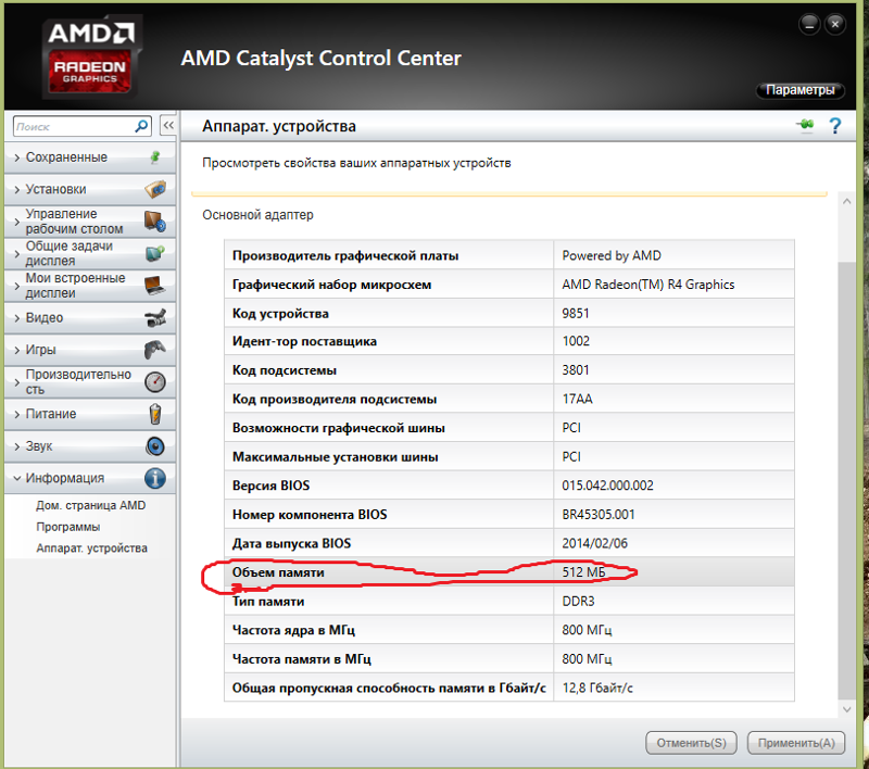 Like HWMonitor, it can also keep your RAM in check but, most importantly, in today’s context, it allows you to adjust the fan speed manually.
This is quite useful as the fan speed isn’t always automatically adjusted when the card is placed under more strain. At the cost of extra electricity, you can crank up those RPMs and enjoy a smooth gaming experience.
Download open hardware monitor
SpeedFan
Continuing the theme of old-school software, SpeedFan is another reliable solution. In addition to the standard monitoring of voltage, fan speed, and temperature, it can adjust the RPM of fans as well as help to reduce the noise.
Download SpeedFan
MSI Afterburner
It’s impossible to discuss hardware monitoring software without mentioning MSI Afterburner.
This tool is the perfect solution for measuring the performance of your GPU while you’re playing a game, as it features a nifty overlay that tells you exactly how hot your GPU temperature is.
You obviously won’t want to run every game constantly with this overlay, but it’s a great solution for a stress test that can help you either adjust your in-game settings or fan speed, something MSI Afterburner can also help with.
download msi afterburner
HWMonitor
HWMonitor is a relatively old tool but is still incredibly reliable. In addition to monitoring your GPU temperature, HWMonitor can also help you keep an eye on voltage and fan speed of other PC hardware such as the CPU, hard drive, and motherboard.
download Hwmonitor
How to Check Your CPU Temperature
How hot is your PC running, and why is this important? You can find the answers in one of two ways. You can take the liberty of downloading a tool that will tell you precisely what you want to know, or you can use a hardware monitor.
Contents
- Windows apps
- Hardware monitors
- On a Mac? Try TG Pro
Keeping your PC cool is as important as keeping water in a radiator. When they fry, it could mean a whole new machine is needed. Let’s avoid this problem together.
Windows apps
You don’t need to get into the nitty-gritty of UEFI/BIOS to measure your CPU’s temperature. Monitoring applications use the same physical temperature sensors in your system as your UEFI/BIOS, but make it accessible right through Windows. That means you can check it without a restart and you can also force your CPU to do something difficult so you can see how warm it gets when it’s working hard.
There are a number of first- and third-party apps out there that you can use to get quick and easy access to your CPU’s temperature, as well as a lot more information. Some of them can be a little overwhelming, but if you’re just looking to find out how to check your CPU temperature, our favorites listed below will see you right.
Intel XTU
If you have an Intel Core processor, then Intel’s Extreme Tuning Utility (XTU) is arguably the best way to check how hot your processor is running.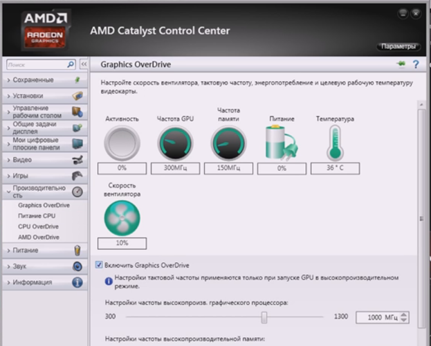 Although designed primarily as an overclocking tool, Intel XTU comes with a number of built-in monitoring functions as well.
Step 1: To find out how hot your CPU is when running it, download the program from Intel’s download center and install it like you would any application.
Step 2: While booting it up, you’ll be presented with a lot of information, but in the lower panel of the main screen, you’ll see a few pieces of key information about your CPU. Most important for this particular guide is the package temperature and associated graph. That’s your CPU temperature.
Step 3: You can also see how hard your CPU is working by its CPU Utilization percentage. The higher that is, the more your CPU is having to do. If you want to see how it does under stress, you can use XTU’s built-in CPU benchmark under the relevant left-hand tab.
AMD Ryzen Master
Step 1: If you’re running one of AMD’s new Ryzen processors, you can make use of AMD’s own Ryzen Master tool.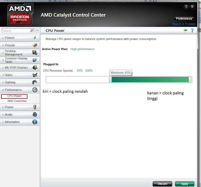 It works in much the same way as Intel’s XTU, but for Ryzen chips instead. Head on over to its download center to install the program.
Step 2: Alongside its core clock-tweaking abilities, it also has a CPU temperature monitor you can view on the left-hand side. Like the XTU, there’s also a graph that can plot your CPU’s temperature over time, even breaking it down by the core, so you can see if individual cores are getting warmer than others.
Step 3: The Ryzen Master tool can also give you average and peak readings, so you can see how hot your CPU gets over a long period, which is great for those concerned about time of day or outside forces affecting CPU temperature.
HWMonitor
A classic PC-monitoring solution, HWMonitor can tell you everything about the various components in your system, from the voltages they require to the temperatures they run. It doesn’t feature any sort of overclocking tools, and its interface is bare-bones, but it’s clean, lightweight, and easy to parse at a glance. Download it here.
The HWMmonitor Pro version, which is available for free with ads, has expanded capabilities and allows you to monitor up to 10 devices, including Android devices. That makes it an ideal pick if you want to monitor temperatures on everything you use (and avoid accidentally damaging your smartphone battery with too much heat).
Hardware monitors
If none of the above methods are quite what you’re looking for when it comes to checking your CPU temperature, you could always opt for a hardware monitor. These typically come as part of fan controllers that slot into one of the optical drive ports on desktop systems. They sometimes use your onboard temperature sensors, but many come with their own wired thermometers to give you additional information about how hot your CPU is getting.
Note: These hardware monitors do require installation to some degree, so be prepared to open up your PC to fit them, or pay to have it done by a professional. For tips on DIY PC building, check out our guide to building your first PC.
Here are some hardware monitors worth considering:
Buy at Amazon Thermaltake Commander FT ($40): The Thermaltake Commander FT is a touchscreen fan controller that provides you with temperature readouts for multiple channels on a 5.5-inch display screen. You can control multiple fans to keep your system from overheating and lets you monitor your CPU closely.
Buy at Amazon Kingwin Performance FPX-007 ($35): Although we price this controller at $35, you can usually get it cheaper. The Kingwin fan controller lets you monitor up to five temperatures, including CPU, simultaneously and control five different fans. We especially like the feature that sounds an alarm so you know if your CPU is getting too hot. This alert gives you time to power down your computer before it overheats.
Aerocool Fan V12XT Fan and Temperature Controller ($37): Aerocool’s monitor lets you control as many as four sets of temperature readings and fans with its LCD touchscreen. You’re able to keep the CPU’s temperature displayed on your screen so you can monitor it and easily control the settings for the fans. You can set the alarm to alert you of dangerously high internal temperatures as well.
On a Mac? Try TG Pro
TG Pro is our top pick for Mac users. This is an app that lets you monitor the internal temperature of your computer while controlling the fan.
Apple has verified the TG Pro app and confirms that all macOS updates will support it. You can learn more and download it here.
Editors’ Recommendations
-
Best HP Envy deals for October 2022
-
New phishing method looks just like the real thing, but it steals your passwords
-
The best Chromebooks for 2022: great choices at every price point
-
The best external hard drives for 2022
-
Best Microsoft Surface Laptop deals: Prices from $490
11 BEST CPU Temperature Monitor Software for Windows [2022]
ByMatthew Martin
Hours
Updated
Monitoring the temperature of the processor is essential because it can affect the performance of your PC. The processor houses many computer parts like motherboard, hard disk, etc. Heat can damage these components.
CPU temperature monitors tools help you to overcome this situation. These applications check computer system sensors like temperature, fan speed, voltage, and give you precise information. You can effortlessly detect problems with this data.
Following is a handpicked list of Top CPU Temperature Monitors tools, with their popular features and website links. The list contains both open source(free) and commercial(paid) software.
CPU Temp Monitoring Software to Check Windows PC Temperature
| Name | Platforms | Link |
|---|---|---|
| ? Paessler CPU Temperature-Monitoring | Linux, Mac, and Windows | Learn More |
| ? SolarWinds Hardware Monitoring Software | Windows, Linux, Solaris, UNIX | Learn More |
| CPU Load Monitor | Windows | Learn More |
| Speccy | Windows | Learn More |
1) Paessler CPU Temperature Monitoring
Paessler is a tool that enables you to monitor the temperature of CPU with ease. This application can be used to check the performance of routers, servers and switches.
Features:
- It helps you to ensure the stability of CPU.
- Provides maps and dashboards.
- It is flexible and customizable.
- You can get quick notification when the usage of CPU exceeds.
- Helps you to reduce the CPU overload.
Visit Paessler CPU >>
2) SolarWinds Hardware Monitoring Software
SolarWinds Hardware Monitoring Software is application that enables you to check the health of your computer hardware with ease. It helps you to manage different IT infrastructure from single customizable screen.
Features:
- It enables you to prevent performance issues that are caused by hardware failure.
- This application can prevent outages with hardware monitor.
- It can diagnose hardware and server downtime.
- You can identify and track changes to software and hardware configuration to solve issues.
- It can collect a wide range of information including CPU temperature and fan speed.
Visit Hardware Monitor
3) CPU Load Monitor
Engineer’s Toolset is a CPU temperature monitoring tool that enables you to configure and manage logs with ease. This tool helps you to monitor network stress with ease.
Features:
- Offers real time monitoring and alerting.
- Helps you to monitor the load on the CPU.
- It can scan the IP address to locate the range of IP addresses.
- This app can analyze memory utilization.
- It helps you to enhance network security.
- Integrate with SolarWinds NPM (Network Performance Monitor) solution.
Visit CPU Load Monitor
4) Speccy
Speccy is a CPU temperature monitoring software that runs on windows operating system. This tool shows user information related to the hardware and software of the PC. You can use this software to know the type and amount of RAM in your computer system.
Features:
- Provides a quick summary of hardware installed in your system.
- It offers detailed information about the hardware.
- You can see the real-time temperature of the CPU.
- It allows you to save your result as a snapshot, text file, or XML for easy sharing.
- This software updates automatically.
- It enables you to find the problem that occurs in your system.
Visit Speccy >>
5) HWMonitor
HWMonitor is a program that reads PC systems sensors like temperature, fan speed, voltages, etc. It is one of the best CPU monitoring software which can be used on the Windows and Android operating systems. This tool can monitor PC or mobile using a TCP/IP connection.
Features:
- You can manually edit sensor labels.
- This CPU temperature monitor software has a firewall that can detect non declared port access.
- Generate the logging graph as a bitmap file.

- This PC temp monitoring tool has improved interface with editable sensor labels.
- You can check CPU utilization and bandwidth.
Link: https://www.cpuid.com/softwares/hwmonitor-pro.html
6) Core Temp
Core Temp is a simple tool to check the CPU temp of an x86 based processor. It is one of the best CPU temp monitor that supports all manufactures like AMD (Advanced Micro Devices, and Intel,etc.).
Features:
- Core Temp is easy to use.
- This tool to check CPU temperature Windows 10 accurately read directly from DTS (Digital Thermal Sensor).
- This PC temperature monitor enables a high level of customization.
- This CPU temperature monitor Windows 10 provides a platform for plugins that allow developers to add new features.
Link: https://www.alcpu.com/CoreTemp/
7) SIW
SIW is a downloadable Windows-based software that offers functional and advanced system information for PC. It is one of the best CPU temperature monitor that can gather details about the system and display it in easy to understand format.
Features:
- It is one of the best PC temperature programs that allows you to create a report file in HTML, TXT, XML, or CSV format.
- Supported client platforms are Windows 10, Windows 8.1, Windows 7, etc.
- You can use it for computer hardware and software, network information, software licensee management, security audit, etc.
- It does not require any installation to check computer temperature.
- You can run this software from a network drive, flash drive, domain login script, etc.
- This tool supports server platforms like Windows 2019, Windows 2016, Windows 2012, etc.
- Software updates periodically so that you can get an accurate result.
Link: https://www.gtopala.com/
8) Real Temp
Real Temp is a temperature monitoring software specially designed for all Intel processors. It is one of the best computer temperature monitor tool which can individually adjust the temperature for each core of the CPU.
Features:
- The program depends on temperature data, which is gathered using a Fluke 62 IR Thermometer.
- Test sensors that check your DTS (Data Transformation Services) sensors for any sign of problems.
- You can keep track of the minimum and maximum temperatures.
- Quick, very accurate, and repeatable programs that are running.
- You do not require to install this CPU temperature monitor software or to modify the registry.
Link: https://www.techpowerup.com/realtemp/
9) HWiNFO
HWiNFO is a free software for windows. It is one of the best CPU temp monitor that gives you a quick overview as well as detailed information on hardware components. You can use this PC monitoring software and save custom or full reports on a portable device.
Features:
- This CPU temperature monitor software is easy to read and navigate.
- You can export a report on select devices.
- This PC temperature check tool allows you to copy specific results out of this software.
- It also includes the DOS version as well as a portable version.
- HWiNFO releases program updates regularly.
Link: https://www.hwinfo.com/
10) SpeedFan
SpeedFan is a hardware monitoring tool that can monitors fan speeds, voltages, and temperatures in PC. This tool can change PC fan speed depends on the temperature of hardware components.
Features:
- It is one of the best computer temp monitoring software that supports the SCSI (Small Computer System Interface).
- It can change FSB (Frontside Bus) on some hardware.
- SpeedFan can help you to reduce noise.
- This CPU heat monitor software works with Windows.
- It can access temperature sensors and can even change the fan speed.
Link: http://www.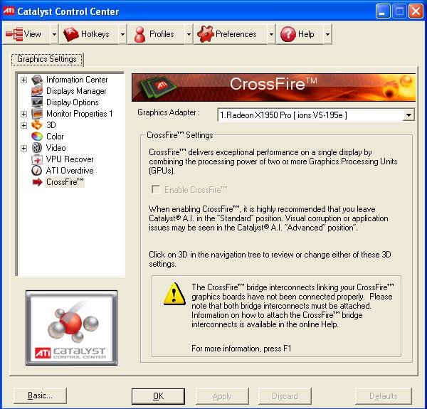 almico.com/speedfan.php
11) Open Hardware Monitor
The Open Hardware Monitor is a free tool that monitors CPU temperature, fan, and clock speeds voltages of a PC. It is one of the best PC temp monitoring software that checks CPU temperature by reading sensors of AMD and Intel.
Features:
- This laptop temperature monitor tool can display the temperature of a hard drive.
- You do not need any installation to use this GPU temp monitor software.
- This PC temp monitoring software runs on 32 bits, and 64-bit Windows operating systems.
- You can quickly view monitored values from the main window, in a customizable desktop, or in the system tray (the area which is located in the Windows taskbar).
Link: https://openhardwaremonitor.org/
FAQ
❓ Why monitoring the temperature of the processor is essential?
Monitoring the temperature of the processor is essential because it can affect the performance of your PC. The processor houses many computer parts like motherboard, hard disk, etc. Heat can damage these components.
? What are the Best CPU temperature monitoring tools?
Below are some of the best CPU temperature monitoring tools:
- Paessler CPU Temperature Monitoring
- SolarWinds Hardware Monitoring Software
- CPU Load Monitor
- Speccy
- HWMonitor
- Core Temp
⚡ What are CPU temperature monitoring tools?
CPU temperature monitoring tools check sensors like temperature, fan speed, voltage, and give you precise information. These applications help you to detect problems with this data effortlessly.
? Mention the general features of CPU temperature monitoring tools?
The general features of CPU temperature monitoring tools are:
- It enables a high level of customization.
- You can check CPU utilization and bandwidth.
- It offers detailed information about the hardware.
- You can see the real-time temperature of the CPU.
❓ How to check CPU temperature?
Below is a step by step process to check the CPU temperature on your PC or laptop:
- Step 1) Download any of the above-listed software
- Step 2) Install the software on your PC or laptop
- Step 3) Open the software
- Step 4) Find the temperatures of your processors in the software dashboard
? How to Reduce CPU Temperature?
You can follow the below steps to reduce the CPU temperature:
- Keep your computer away from vents or windows
- Clean the fans of your computer
- Remove any obstacles which restrict airflow from the computer
- Upgrade the CPU fan if the stock cooling fan does not work properly
- Try to add additional cooling fans if there is a space available in your case
- Try water cooling or liquid cooling if you are using your PC intensively like gaming purpose
- Take extra precautions while overclocking your CPU
MSI Afterburner VS Catalyst Control Center
Software Alternatives & Reviews
Register
|
Login
MSI Afterburner
-
Guru3D
-
Open Hardware Monitor
-
Geforce Experience
-
NZXT CAM
-
OBS Studio
-
EVGA Precision
-
ASUS GPU Tweak
Tool to manage video cards.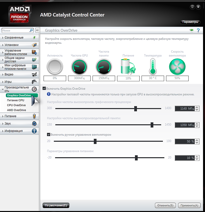 Shows video card stats (temp, GPU usage, etc.).
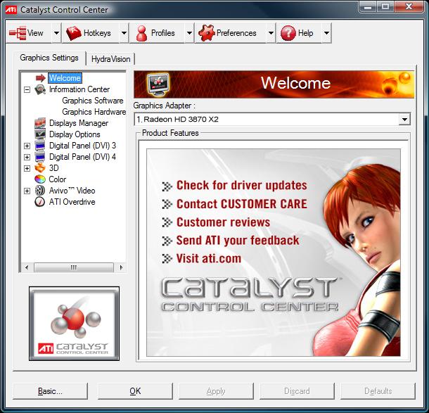
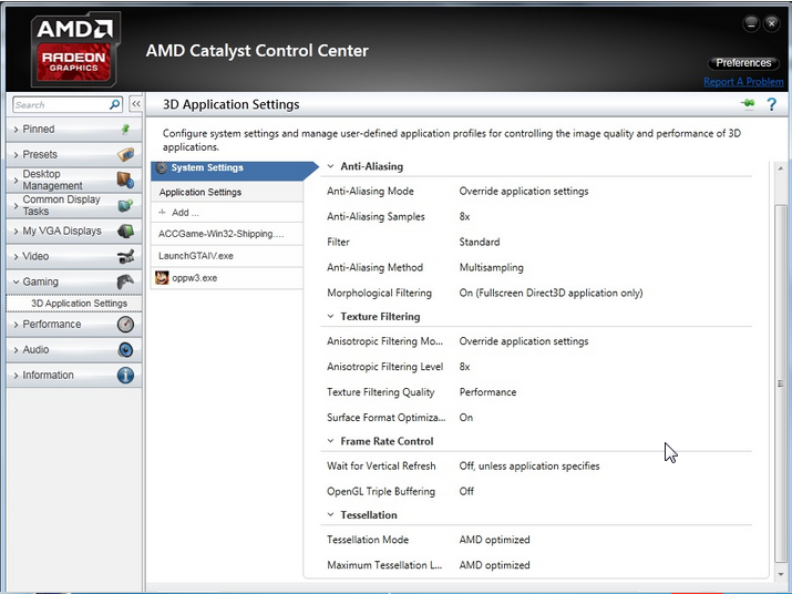
Catalyst Control Center
-
Guru3D
-
ATI Tray Tools
-
ASUS GPU Tweak
-
PowerStrip
-
EVGA Precision
-
Geforce Experience
-
GMABooster
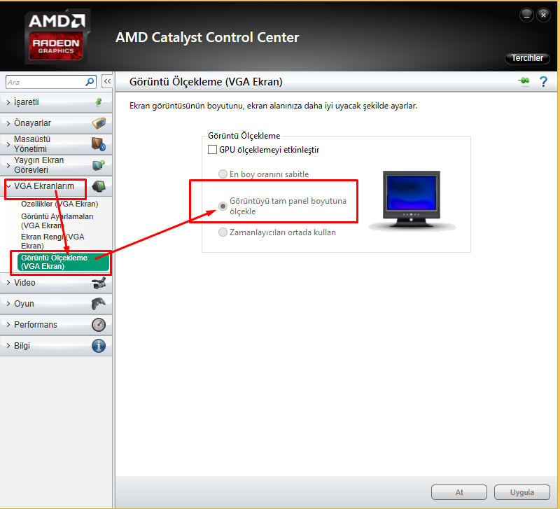
The AMD Catalyst Control Center allows you to control every aspect of your ATI graphics card…
MSI Afterburner Landing PageCatalyst Control Center Landing Page
MSI Afterburner details
| Categories |
Gaming |
|---|---|
| Website |
msi. com com |
Suggest changes
Catalyst Control Center details
| Categories |
Gaming |
|---|---|
| Website |
amd.com |
Suggest changes
MSI Afterburner videos
+ Add
MSI Afterburner — How to setup On-Screen Display
More videos:
-
Tutorial
—
MSI Afterburner Complete Guide & Tutorial 2019 -
Review
—
MSI Afterburner! GPU Overclocking for Beginners.
Catalyst Control Center videos
+ Add
Review: My PC Peripherals; Components; ATI Catalyst Control Center
More videos:
-
Review
—
New Catalyst Control Center 2011 — overview
Category Popularity
0-100% (relative to MSI Afterburner and Catalyst Control Center)
MSI Afterburner
Catalyst Control Center
Gaming
Note Taking
100%
100
100
100%
Monitoring Tools
100
100%
Video Recording
Reviews
These are some of the external sources and on-site user reviews we’ve used to compare MSI Afterburner and Catalyst Control Center
MSI Afterburner Reviews
11 Best CPU Temperature Monitor For Windows PC To Check Accurate CPU Temp Readings
MSI Afterburner is the world’s most famous graphics card overclocking software that is used by millions of users even in 2021. If you want to overclock your CPU or GPU then you can download MSI Afterburner. You can also check CPU temp and GPU temp, monitor CPU fan speed, CPU frequency, load.
Source:
www.softlay.com
Top 10 Best Game Booster Software Windows 2020
Last yet not the least in the rundown of best Game Booster programming for Windows, MSI Afterburner is an incredible sponsor for Windows 10. This is one of only a handful couple of programming like GameBoost which offers overclocking alternatives. Aside from the typical capacities, it gives the client a chance to tweak the fan speed, benchmark video record, and screen. It…
Source:
techigem.com
11 Best Game Optimizers and Boosters for Windows PC
Meet the best game booster software, MSI Afterburner for your Windows 10 machine. This is one of the few solutions which offer overclocking options.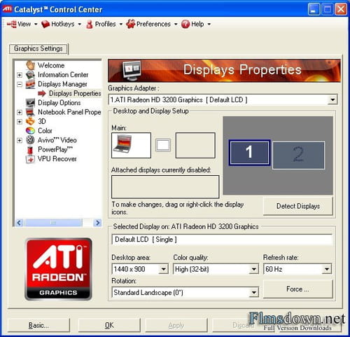 Apart from the usual functions that every top game speed boosting tool provides, it lets the user customize the fan speed, benchmark video record, and monitor. It offers full control over the GPU voltage and frequency. You can…
Source:
blogs.systweak.com
Catalyst Control Center Reviews
We have no reviews of Catalyst Control Center yet.
Be the first one to post
What are some alternatives?
When comparing MSI Afterburner and Catalyst Control Center, you can also consider the following products
Guru3D
— Guru of 3D: PC Hardware Reviews and tests
Open Hardware Monitor
— Monitors temperature sensors, fan speeds, voltages, load and clock speeds, with optional graph.
ATI Tray Tools
— This tool is developed by Ray Adams.
Geforce Experience
— GeForce Experience is a new application from NVIDIA that optimizes your PC in two key ways.
ASUS GPU Tweak
— ASUS GPU Tweak fully implements TechPowerUp’s GPU-Z analysis and monitoring features.
NZXT CAM
— CAM is a piece of software that was designed by NZXT, one of the industry leaders in the world of gaming PC production.
MSI Afterburner vs Guru3D
MSI Afterburner vs Open Hardware Monitor
MSI Afterburner vs ATI Tray Tools
MSI Afterburner vs Geforce Experience
MSI Afterburner vs ASUS GPU Tweak
MSI Afterburner vs NZXT CAM
Catalyst Control Center vs Guru3D
Catalyst Control Center vs Open Hardware Monitor
Catalyst Control Center vs ATI Tray Tools
Catalyst Control Center vs Geforce Experience
Catalyst Control Center vs ASUS GPU Tweak
Catalyst Control Center vs NZXT CAM
User reviews
Share your experience with using MSI Afterburner and Catalyst Control Center.
For example, how are they different and which one is better?
Do not miss the top trending startups with our weekly report!
P0425 — Catalytic converter temperature sensor, bank 1
OBD-II DTC Datasheet
1, sensor 1)
What does this mean?
This Diagnostic Trouble Code (DTC) is a generic transmission code that means it applies to OBD-II vehicles equipped with a catalyst temperature sensor (Subaru, Ford, Chevy, Jeep, Nissan, Mercedes-Benz, Toyota, Dodge etc. ). ). Although general, the exact repair steps may vary by make/model.
The catalytic converter is one of the most important exhaust equipment in a car. Exhaust gases pass through a catalytic converter where a chemical reaction takes place. This reaction converts carbon monoxide (CO), hydrocarbons (HO) and nitrogen oxides (NOx) into harmless water (h4O) and carbon dioxide (CO2).
Converter efficiency monitored by two oxygen sensors; one installed upstream of the converter and one installed downstream. By comparing the oxygen (O2) sensor signals, the powertrain control module (PCM) can determine if the catalytic converter is working properly. A standard O2 sensor with zirconium pre-catalyst will quickly switch its output between approximately 0.1 and 0.9Volt. A reading of 0.1 volts indicates a lean air/fuel mixture, while 0.9 volts indicates a rich mixture. If the converter is working properly, the output sensor should be constantly operating at about 0.45 volts.
Catalytic converter efficiency and temperature go hand in hand.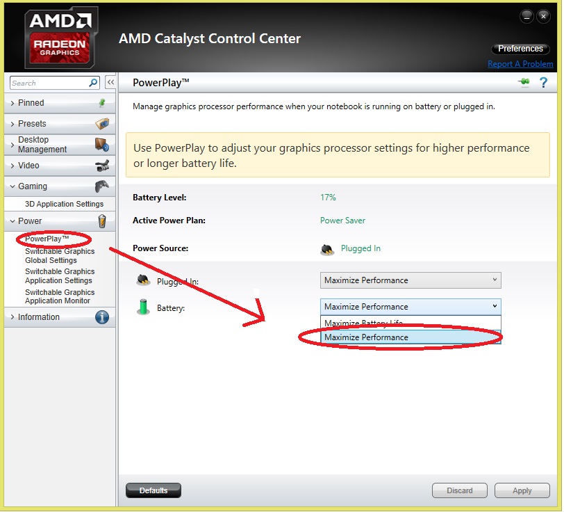 If the converter is working properly, the outlet temperature should be slightly higher than the inlet temperature. The old rule was a difference of 100 degrees Fahrenheit. However, many modern vehicles may not show such a large discrepancy.
There is no true «catalyst temperature sensor». The codes indicated in this article are an oxygen sensor. The «bank 1» part of the code indicates a problem with the first bank of the engine. That is, the bank that cylinder number 1 is in. «Sensor 1» refers to the sensor installed before the catalytic converter.
DTC P0425 is set when the PCM detects a malfunction in Catalyst 1 Temperature Sensor Circuit Bank 1.
Associated DTCs include:
- P0426 Catalyst Temperature Sensor Circuit Range/Performance (Bank 1 Sensor 1)
- P0427 Catalyst Temperature Sensor Circuit Low (Bank 1 Sensor 1)
- P0428 Catalyst Temperature Sensor Circuit High Temperature (Bank 1 Sensor 1)
Code severity and symptoms
The severity of this code is moderate. Symptoms of a P0425 engine code may include:
- Illuminated engine light
- Bad operation of the engine
- Fuel consumption decrease
- Extensions of
Reasons
Possible reasons for this P0425 code include:
- Oxygen Blessed Sensor Sensor Problems with
- EXPRISE OF AIRS and OUTSE AIRS
- Faulty PCM/PCM programming
Diagnostic and repair procedures
Start by visually inspecting the upstream oxygen sensor and related wiring. Check for loose connections, damaged wiring, etc. Also, check for exhaust leaks both visually and audibly. An exhaust leak can cause a false oxygen sensor code. If corruption is found, repair as needed, clear the code and see if it comes back.
Then check the Technical Service Bulletins (TSB) for this issue. If nothing is found, you will need to proceed to a step by step system diagnostic. The following is a generalized procedure as testing for this code varies by vehicle.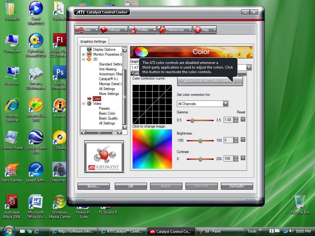 In order to accurately test the system, you will need to refer to the diagnostic flowchart for the specific vehicle make/model.
Check for other DTCs
Oxygen sensor codes can often be set due to engine performance problems that result in an air/fuel mixture imbalance. If other DTCs are stored, you should refer to them first before proceeding to diagnose the oxygen sensor.
Check sensor operation
The best way to do this is with a diagnostic tool or better yet an oscilloscope. Since most people don’t have access to a scope, we’ll look at diagnosing the oxygen sensor with a scan tool. Connect the diagnostic tool to the ODB port under the dashboard. Turn on the scan tool and select the bank 1 sensor 2 voltage parameter from the data list. Bring the engine to operating temperature and view sensor activity on the scan tool in graphical mode. The sensor should quickly switch between saturated and lean (0.1 volts and 0.9volt). If the sensor response is sluggish, it is probably defective and should be replaced.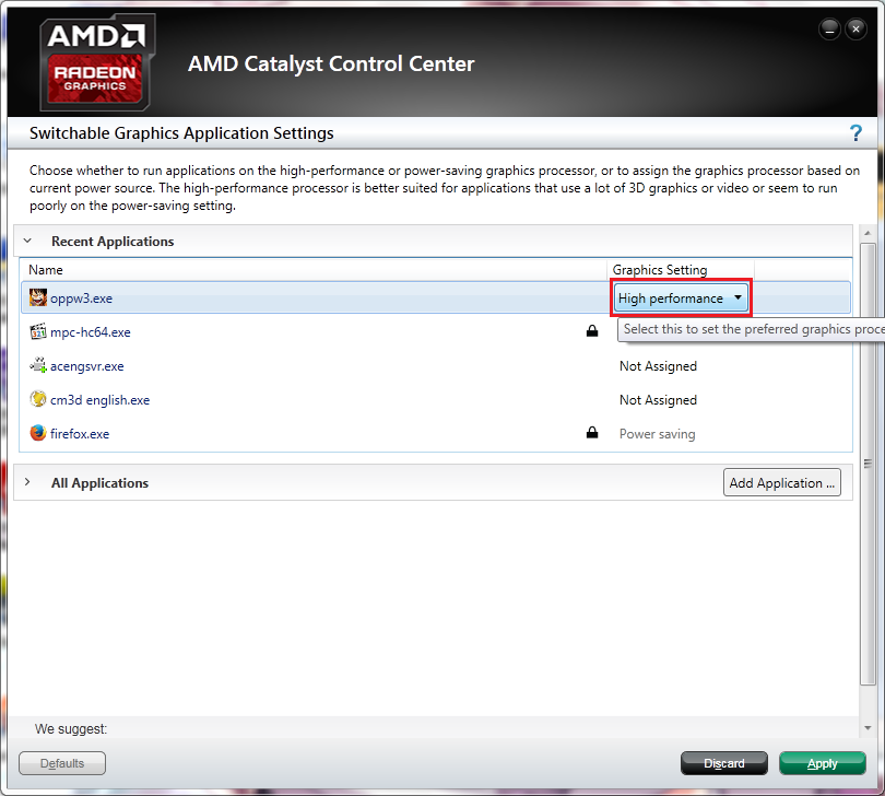
If the sensor reading is consistently higher than 0.55 V, or if the sensor has failed, the air/fuel mixture is too rich, or there is an open in the sensor signal circuit. If the sensor reading is consistently above 0.35 volts, or the sensor has failed, the air/fuel mixture is too lean, or there is a high resistance or short circuit in the signal wire to the PCM.
Check diagram
The oxygen sensors produce their own voltage signal, which is sent back to the PCM. Before proceeding, you can refer to the factory wiring diagrams to determine which wires are which. Autozone offers free online repair manuals for many vehicles and ALLDATADIY offers a single vehicle subscription. To test for continuity between the sensor and the PCM, turn the ignition key to the off position and disconnect the O2 sensor connector. Connect a digital multimeter with ohms (ignition OFF) between the O2 sensor signal terminal on the PCM and the signal wire. If the meter reading is out of range (OL), an open circuit exists between the PCM and the sensor, which must be found and repaired.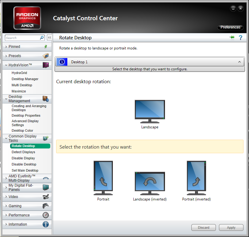 If the counter reads a numeric value, there is continuity.
Next you need to check the grounded circuit. To do this, turn the ignition key to the off position and disconnect the O2 sensor connector. Connect a DMM with resistance (ignition OFF) between the ground terminal of the O2 sensor connector (wiring harness side) and chassis ground. If the meter reading is out of range (OL), there is an open circuit on the ground side of the circuit that needs to be located and repaired. If the meter reads a numeric value, there is ground continuity.
Finally, you need to make sure the PCM is processing the O2 sensor signal correctly. To do this, leave all connectors connected and insert the rear probe test lead into the signal terminal on the PCM. Set the DMM to DC voltage. With the engine warm, compare the voltage reading on the meter with the reading on the scan tool. If the two do not match, the PCM is probably faulty or needs to be reprogrammed.
Catalyst Regeneration Temperature Limits — Chemist’s Handbook 21
The dehydrogenation of butenes to butadiene is carried out in a system of two reactors with a fixed catalyst bed. One apparatus operates in the dehydrogenation mode, the second in the catalyst regeneration mode (Fig. 5.7) [5]. The regeneration of the catalyst is carried out with a steam-air mixture at a temperature of 620-650 C. The oxygen concentration in the gas mixture is in the range of 1-2% (vol.). The duration of the entire cycle (dehydrogenation + regeneration) is approximately 30 minutes. The operation of transition from the dehydrogenation phase to the regeneration phase consists in replacing butene in the gas-vapor mixture with a certain amount of air [c.108]
In each particular case, a number of limitations may arise in the regeneration of the catalyst associated with the design of the reactor pressure vessel. So, when using lined reactors, restrictions are imposed on the rate of rise, (decrease) in temperature and pressure of the process. For the grades of shotcrete used, it is possible to recommend a rate of temperature rise in the range of 10–12, and a decrease of 8–10 °C/h. In the case of bimetallic cases unprotected from the inside with a lining, the temperature in the apparatus should not exceed 500 °C.
[c.129]
The instrumentation of the process is largely similar to the schemes of modern catalytic reforming units. The general scheme is close to that used in hydrocracking units of the initial period. The temperature is within. 260–400°C, pressure 52–133 atm, depending on the nature of the raw material and the purity of the available hydrogen. Usually the process is carried out in two stages, although in some conditions it is more appropriate to use a single stage option. Long periods of operation are achieved between catalyst regenerations or until the catalyst needs to be replaced. In industrial installations under design conditions, the catalyst life is usually more than 1-2 years. [c.64]
One of the most interesting and industrially important heterogeneous catalytic processes developed 5a in the last fifteen years is the catalytic reforming of straight-run and cracked naphthas to produce high-octane gasolines and individual aromatic hydrocarbons.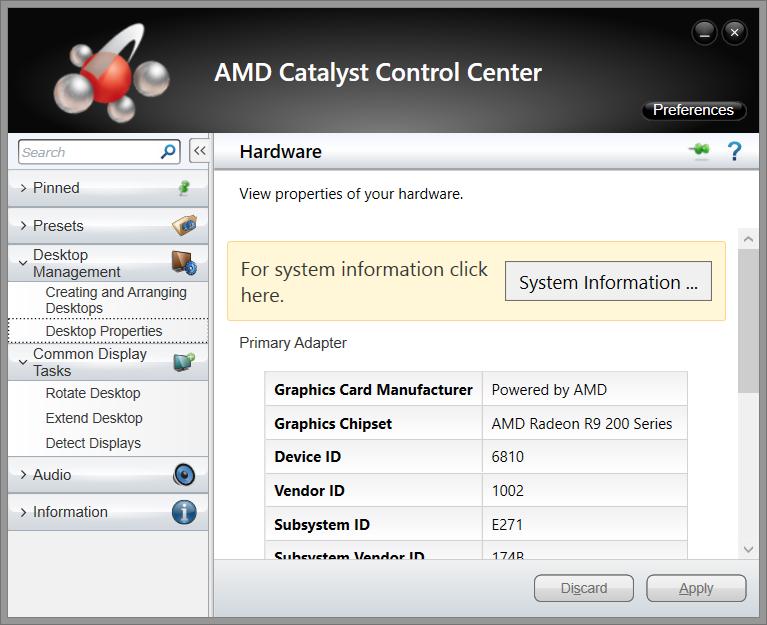 In this area, hydrogenation-dehydrogenation catalysts (molybdenum and chromium oxides) were used. Studies carried out at atmospheric pressure have shown that these catalysts have sufficient activity and selectivity in the reactions of reforming hydrocarbons with boiling points lying within the boiling points of naphthas. Although these catalysts lose their activity as a result of coke deposition, it can be almost completely restored by air regeneration. [c.464]
Temperature limits. Excess temperature during regeneration is the most common cause of irreversible destruction of the catalyst, and sometimes even the reactor. Here are some examples [c.121]
Temperature increase during regeneration became possible with the use of zeolite-containing catalysts. The trend of increasing the temperature has been outlined recently with the aim of afterburning carbon monoxide in the regenerator itself. This is also necessary to reduce the coke content in the regenerated catalyst, especially in a zeolite-containing catalyst, where the coke content is limited within the range of 0. 15–0.05 wt.%. The pressure in the settling zone of the regenerator is usually maintained within 0.03-0.27 MPa. The frequency of circulation of the catalyst to the raw material depends on the type of system and ranges from 3 1 to 10 1. [c.68]
C. The middle zone in the form of a lift reactor connects the lower and upper regeneration zones. The device of the middle regeneration zone in the form of a transport line facilitates the exchange of heat between the catalyst and regeneration gases. The temperature in this zone is in the range of 482-760 °C. After the middle regeneration zone, the catalyst passes through cyclone separators and enters the upper regeneration zone. The temperature in this zone can be in the range of 538-871 C. Then part of the regenerated catalyst enters the lower regeneration zone to maintain the required temperature there. A feature of the process is the partial regeneration of the catalyst in one of the zones of the reactor. [c.132]
After heating in the F02 furnace to a temperature of 255 °C, process gases enter the B04 converter in three streams. The B04 converter is filled with 80 tons of R-type catalyst, laid on a layer of ceramic balls. The process gases pass from top to bottom of the catalyst bed, on the surface of which the Claus reaction and the hydrolysis of OS and S2 take place. Since these reactions proceed with the release of heat, process gases at the outlet of the converter have a temperature 60-100 °C higher than at the inlet. The temperature of the gases at the outlet of the converter must be within the range of up to 355 °C in normal mode and up to 400 °C during catalyst regeneration. To condense sulfur vapor and release it in liquid form, process gases are cooled to a temperature of 173 ° C in the E02 condenser tube bundle and B05 coagulator, from where they enter the ROZ preheating furnace. Liquid sulfur from the B05 coagulator is discharged through hydraulic seals into the TOI sulfur pit.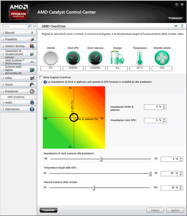 [c.109]
Obviously for catalytic processes on the surface of solid catalysts is the heating of raw materials (gasoline, diesel, vacuum distillates, fuel oils) to the appropriate temperatures and under a certain pressure, contact with the catalyst surface (usually in reactors), separation of reaction products and catalyst regeneration (in regenerators). When oil feedstock is heated in furnace coils, CCEs of varying degrees of polydispersity and life expectancy are formed. The lifespan of CCE is understood as the period from the onset of CCE in the initial phase to its destruction with the formation of a new phase. The lifetime depends on the nature and size of the nucleus (g) and the thickness and nature of the adsorption-solvation layer (/g) of the CCE, on external influences on the system, and can vary within wide limits. Life expectancy during the phase transition is the smallest for gasoline fractions and increases with the transition to raw materials with high values of s. t of intermolecular interaction (for example, to fuel oil). [c.202]
This process has the following advantages compared to sulfuric acid 1) full and simple regeneration of the catalyst is carried out within the plant itself, since the release of spent hydrofluoric acid from tar compounds and water is achieved by distillation 2) no refrigeration is required machines for cooling the reactor, since due to the higher temperature of the process, heat removal is achieved by water cooling. The ease of catalyst regeneration makes it possible to profitably involve propene and pentenes in the process (in the case of the sulfuric acid process, this would be associated with an increased consumption of acid) .
[c.283]
The possibilities of carrying out processes on catalysts with rapidly decreasing activity in capacitive apparatuses are limited, since in the absence of heat exchange devices, the heat released in the highly exothermic regeneration process can lead to catalyst sintering and loss of activity.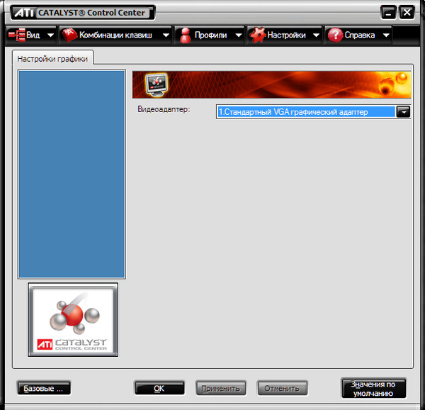 If the adiabatic heating temperature during regeneration exceeds the thermal stability limit of the catalyst, it can be reduced by diluting the regenerating agent (air) with nitrogen or water vapor. [c.160]
9 [40, 47, 48]. The preheated raw material at a temperature of 200–220 °C is fed into the tube furnace L, where it is still heated to 500 °C, and then enters the reactor 2. The temperature in the reactor is maintained within 480–500 °C, pressure, 7–2.2 kgf/cm. The vaporous reaction products are removed from the reactor and sent to distillation column 9, where they are separated into gas-gasoline and gas-oil fractions. From hopper 3, catalyst with a temperature of 520–540°C continuously flows by gravity into the upper part of reactor 2. The spent catalyst from the bottom of the reactor enters apparatus 4 for stripping liquid cracking products. Further, the catalyst is sent by the lifter 5 to the regenerator 6, where coke is burned off the catalyst surface. The regenerated catalyst is returned to the reactor using a lifter 5 of the same type. The exhaust gases of regeneration for purification from catalyst dust are sent to the apparatus 7 and to the cyclone separator 8, after which they are removed from the system. [c.38]
The temperature of catalyst regeneration with a mixture of air and inert gas is in the range of 550-600°. At higher temperatures, the strength of the catalyst decreases. [c.259]
The process conditions are determined by the task, which specifies the raw material, the process temperature, the volumetric (or mass) feed rate of the raw material, the duration of the process without catalyst regeneration, etc. The feed rate of the raw material is determined based on the volume of the loaded catalyst and set in the range from 0.5 to 2.0 volumes of raw materials per 1 volume of catalyst per hour (at 0°C). The duration of the experiment is determined by the need to have a sufficient amount of liquid product for subsequent determinations of the yield of gasoline, naphtha and gas oil [c.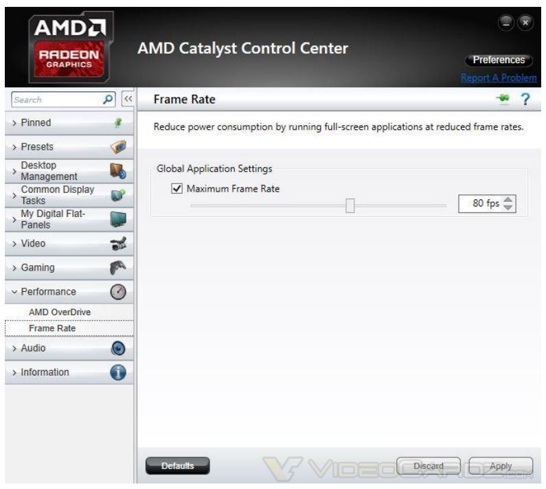 129]
129]
, from where it is transferred to the reactor 4. Here, from the hopper 5, a hot ball catalyst with a diameter of up to 5 mm is continuously fed through the riser pipe 6. The coke-enriched catalyst moves downstream, where it is treated with superheated steam before exiting the reactor to separate volatile hydrocarbons. The hoist 10 feeds the catalyst through the hopper 13 to the regenerator 12. The regenerated catalyst with the addition of fresh hoist 11 is again transferred to the hopper 5. The temperature in the reactor is maintained in the range from 480 to 500°C and the pressure is from 0.7 to 1.1 atm. The catalyst is regenerated at a temperature of about 600°C. The mixture of vapors of cracking products and water vapor leaving the catalyst bed is sent to a distillation column 7, from the top of which gas, gasoline and water vapors enter the condenser 8 and then to the gas separator 9. [c.251]
In periodic regenerations of the catalyst, the fraction of oil boiling away in the range of 140–200°C was introduced into the upper part of the reactor, in which the temperature was maintained at 100°C. The extraction was continued for 12-15 hours until the paraffin content in the catalyst was reduced to 1-2%. Usually, 2-2.5 tons of paraffin was extracted from one reactor. This method of solvent treatment has usually proved to be sufficient for catalyst regeneration, since in subsequent synthesis the contraction of 55-60% is established at a lower operating temperature. If treatment by this method did not lead to the restoration of activity, then the catalyst was treated with hydrogen passed through the reactor at a rate of 1000 mHac at a temperature of about 200°C for 7-10 hours. at [c.293]
These units are designed to remove acid components (sulphurous anhydride, hydrogen sulfide, etc.) and at the same time to cool the circulating flue gases during the catalyst regeneration cycle. The temperature of the flue gases at the inlet, depending on the intensity of heat exchange in the raw heat exchangers, ranges from 75 to 200 ° C. The scrubbers of the reforming plants are irrigated with water, and in the hydrotreatment of diesel fuels — with an alkali solution. [c.134]
The possibilities of carrying out processes on catalysts with rapidly decreasing activity in capacitive apparatuses are limited, since in the absence of heat exchange devices, the heat released in a highly exothermic regeneration process can lead to catalyst sintering and loss of activity. If the heating temperature during regeneration exceeds the thermal stability limit of the catalyst, [c.264]
The temperature of the catalyst in the B06 converter must be within the range of up to 264 C in normal operating conditions and up to 400 °C during catalyst regeneration. Process gases with temperatures up to 264 °C enter the pipe space of the EOS condenser from the VB converter. Since the reactions occurring on the catalyst are exothermic, the temperature of the gases at the outlet of the converter is 20–40 °C higher than at the inlet. Process gases are cooled in the condenser to condense sulfur vapor. [c.111]
Fluidized bed cracker operates under the following conditions: temperature in the range of 471-527 ° C, overpressure 0.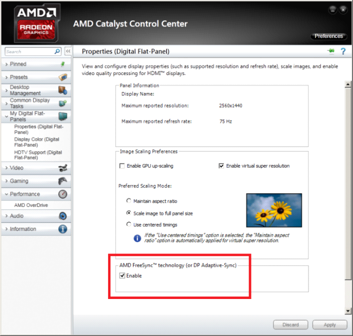 70-1.12 atm, load from 1 to 3 kg-h -kg of catalyst , the ratio of the mass flow rates of the catalyst and raw materials is from 8 to 12. This last indicator characterizes the duration of the use of the catalyst before it becomes necessary to regenerate it. Regeneration mode temperature 566-593 °C, overpressure 0.56-0.7 atm, residence time of the catalyst in the reaction zone of the regenerator from 20 to 40 sec. In a moving bed plant, the process conditions are as follows: temperature from 450 to 493 °, overpressure [c.335]
MPa, gas circulation 600-1100 mVm of raw material, volumetric feed rate of raw material 1-3 h», H1 content in circulating gas 75-95% (vol.). Catalyst 123 1 1 (promoted by rhenium) Catalyst operating time between regeneration is 5–40 days The amount of feedstock processed over the catalyst is up to 180 mVkg of catalyst Temperature during catalyst regeneration is maintained within 427–566°C, pressure 0.7–1.4 MPa, the oxygen content in the inert gas is not more than 2% (vol. ). [c.32]
The ideal displacement model (4.18) is a rather rough simplification of the real picture of coke burning in the catalyst bed. However, with its help, qualitatively correct estimates are obtained. For example, the fact is confirmed that with an increase in the initial coking of the catalyst, the oxygen concentration decreases faster along the bed, and the time required for the complete regeneration of the catalyst increases [147]. An increase in temperature during regeneration can affect the activity of the catalyst [149]. The temperature rises sharply at the beginning, when only a small part of the coke has burned out. In this case, the oxygen concentration and the coke content on the catalyst are quite high, and the reaction rate is the highest. Increasing, the temperature in the reactor tends to a certain asymptotic limit, which depends on qb, Co, and To. made of ferrosilicon or stainless steel. Each shelf of the bubbling hydration column is closer to the mixing mode than to the displacement mode in terms of the degree of gas and liquid mixing.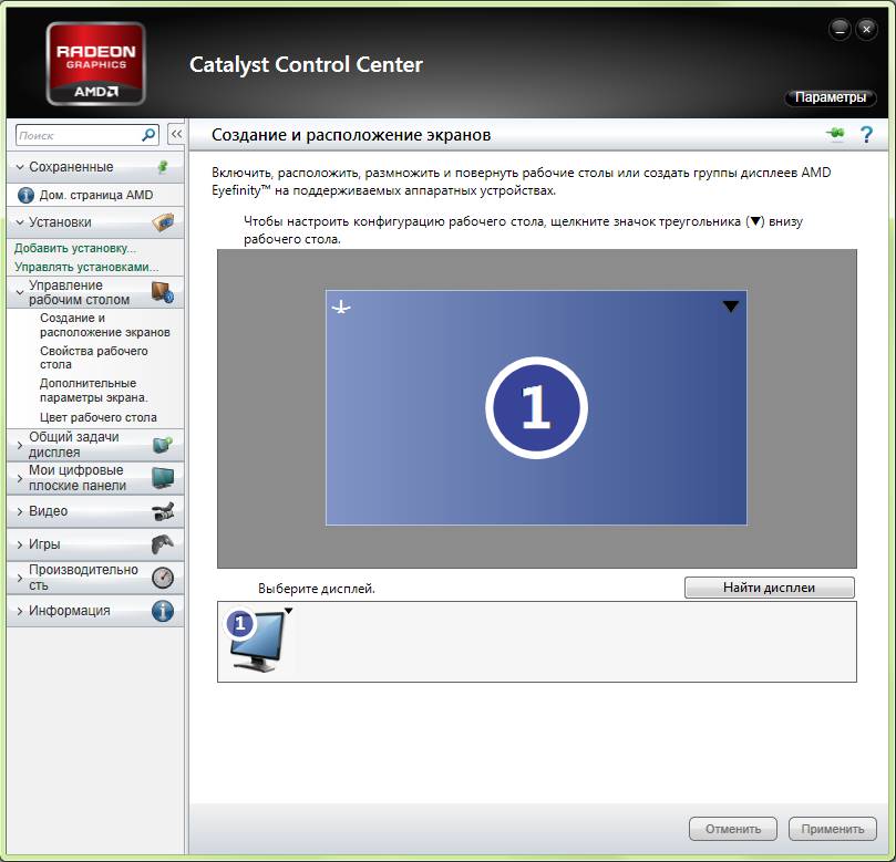 However, due to a significant number of shelves, the process can be calculated according to the displacement model with countercurrent phase movement. The temperature in the hydrator with the help of live steam is maintained within 90–100°. Gases coming out of the top of the hydrator and containing acetaldehyde, unreacted acetylene, water vapour. and other impurities enter the refrigerators. In the first, water vapor is condensed, returned to the hydrator, and in the second, acetaldehyde and water are sent to the collector. Neskondeisirovannyh gases are fed into the absorber, where alde [ide is removed by water cooled to 10 ° C, and unreacted acetylene is returned back to the process. At the same time, about 10% of the gas is continuously taken to remove nitrogen and carbon dioxide, which prevents their excessive accumulation in the circulating gas. Acetaldehyde is further subjected to rectification. The catalyst liquid leaving the hydrator is sent to a sump (to capture mercury) and then to regeneration.
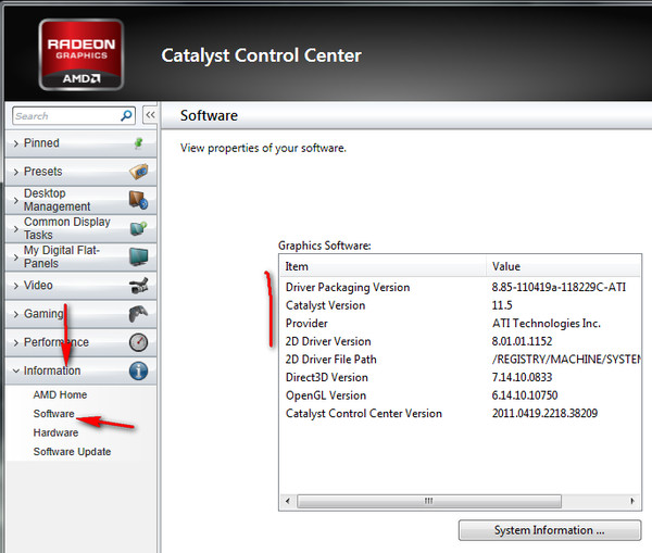 The catalyst liquid contains approximately 200 g/l sulfuric acid, 0.5– [c.183]
The combined use of a two-component zeolite-containing catalyst for the alkylation of isoparaffins with olefins and catalytic cracking is envisaged in the scheme described in [19]. Hydrocarbons boiling within gas oil boiling points are cracked on a regenerated two-way catalyst consisting of a conventional zeolite-containing catalyst and synthetic ZSM-5 zeolite. The process conditions are selected in such a way as to ensure the maximum yield of gasoline and low-boiling hydrocarbon gases containing olefins and paraffins. The gas portion is separated from the gasoline and sent to contact fresh catalyst. The zeolite ZSM-5 contained in it promotes alkylation, cyclization and aromatization. The products of the second stage are mixed with the products of cracking before their fractionation. Coked catalysts from stages I and II of cracking are combined and subjected to regeneration. The regenerated mixture is used for gas oil cracking. [c.270]
Regeneration of the catalyst Hz) is carried out every 3-4 months. in the case of a significant decrease in the activity of the catalyst, which cannot be compensated by a rise in temperature within the limits allowed by the technological regulations. The purpose of regeneration is to burn off the coke deposited on the catalyst during the reaction. [c.36]
In the first layer of the vanadium catalyst at a temperature of 420 C and the volume concentration of SOg indicated above, almost all the amount of SOg is converted into sulfuric anhydride SO3. If the inlet temperature drops to 400°C, the SOg conversion decreases. At the same time, the temperature should not exceed 450°C, as this causes an increase in the temperature at the bed exit to 620°C and a decrease in conversion. Due to the exothermicity of the oxidation reaction of SOg to SO3, the optimum temperature at the outlet of the first catalyst layer is maintained at 580-600°C.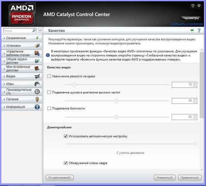 Before entering the second layer, process air is supplied to the flow and the layer is cooled to 440°C. After passing through the second catalyst bed, the outlet temperature of the gas mixture stream is about 460° C. and substantially all of the SOg residue is oxidized to SO3. The completion of the reaction is carried out in the third catalyst layer, where the increase in outlet temperature due to the small amount of SOg in the stream is negligible. To optimize the conversion, the catalyst in the converter is poured evenly so that the gas passes through the entire cross section of the catalyst. After the third conversion stage, the gas flow enters the E-2114 heat exchanger, where it is cooled to 220 C with air from BW-2101A/B blowers. The heat of the air heated to 185-240 C is used to regenerate silica gel and molecular sieves in air dryers. The pre-cooled gas stream then enters the E-2115 refrigerator for final cooling to a temperature of 40°C. Prior to the cooler, process dried air is introduced into the gas stream to dilute SO3 to a concentration of 3.
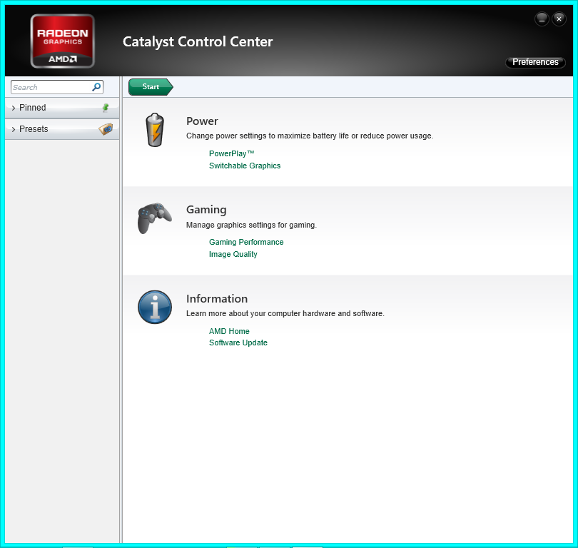 5% vol. Maintaining the temperature of the gas mixture within the optimal range is carried out by automatic control of the temperature and flow rate of the cooling water. When the gas flow passes through the refrigerator, a small amount of oleum may form, which accumulates in its lower [c.303]
Catalyst regeneration is a highly exothermic process. Therefore, during its implementation, measures must be taken to prevent an excessive rise in temperature in the catalyst layer, otherwise thermal deactivation of the latter (sintering), the associated blockage of the converter, and even, as experience has shown, melting and ignition of the steel walls of the apparatus may occur. Accordingly, the permissible upper limit of the regeneration temperature is primarily determined by the heat resistance of the catalyst. Thus, for aluminosilicate cracking catalysts, aromatization catalysts (CrO3 or MoO3 on Al2O3), the regeneration temperature should not exceed 560–590°C [2, 3]. Reducing the heating temperature of the catalyst during regeneration can be achieved both by diluting the regenerating agent (air) with an inert component and by cooling the reaction zone. The regeneration start temperature is apparently determined not only by the structure of the catalyst grains, but also by its composition, since oxides can have some catalytic effect on carbon burnout [4]. Typically, the initial regeneration temperatures lie around 500°C. [c.168]
The duration of catalyst regeneration can vary widely depending on the coke content, the amount of coolant supplied and the process temperature. The amount of coke formed on the catalyst depends on the characteristics of the feedstock being processed and is in the range from 5 to 20% by weight. To remove excess heat, water vapor is used in the amount of 350-900 nm / h per 1 m of catalyst. An increase in the amount of coolant contributes to the acceleration of the process as a whole, however, the coolant flow rate is limited by the hydraulic resistance of the system. The temperature of the process, depending on the characteristics of the catalyst, the design of the reactor and other factors, is maintained no higher than 550 ° C. The pressure during steam-air regeneration is not higher than 3 at. [c.66]
The results obtained by the hydroforming of naphthas were published by G. N. Maslyansky, E. I. Mezhebovskaya, and V. S. Kholyavko. On the one hand, from the point of view of preventing the process of coke formation, the hydroforming process should be carried out at the highest possible hydrogen pressures; however, since aromatization reactions are dehydrogenation reactions, with an increase in hydrogen pressure, the equilibrium will shift towards an increase in the concentration of the initial hydrocarbons. Thus, during hydroforming, the hydrogen pressure should be limited to such limits under which, under the conditions of the chosen temperatures, it would not prevent deep aromatization of the processed raw material. Since hydroforming was carried out with periodic regeneration of the catalyst, for technological reasons it was difficult to work at pressures above 20–30 at.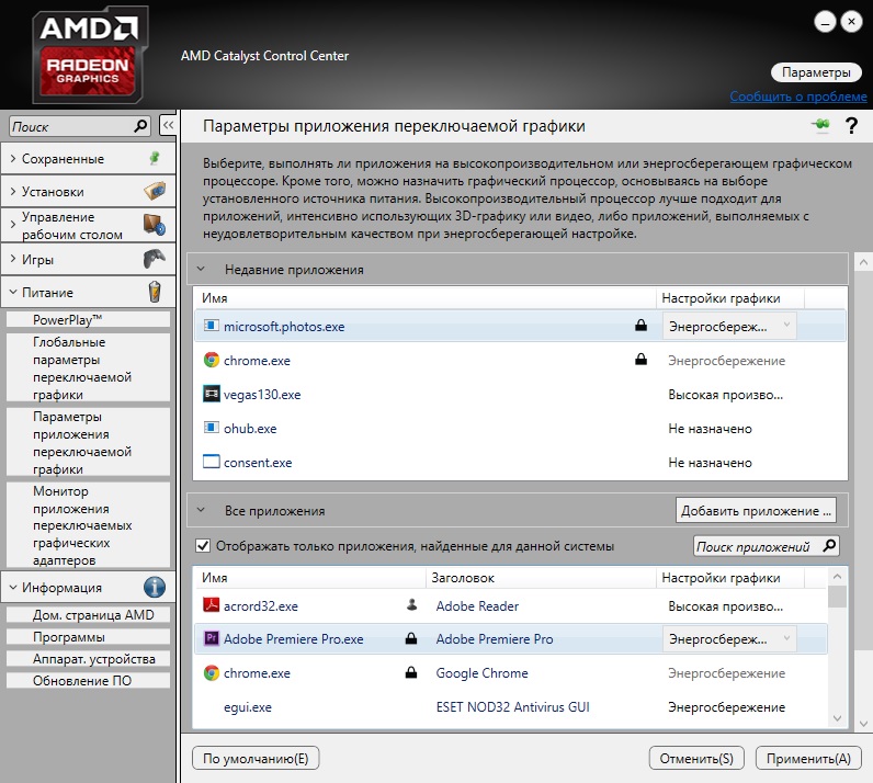 On the basis of thermodynamic considerations, taking into account the equilibrium ratios that develop depending on the temperature and pressure of hydrogen during the aromatization of certain paraffinic and cyclohexane hydrocarbons, the authors0090 [c.256]
With a gradual decrease in the productivity of the plant for raw materials by 20-25%, the process temperature rises due to the relatively greater heat influx into the reactor with the regenerated catalyst. In this case, the space velocity decreases, and the catalyst circulation rate increases. The absolute yield of coke in the process changes insignificantly, which makes it possible to regenerate the catalyst without stress and maintain the residual coke content on the catalyst within 0, -0.26% by weight. [c.48]
Doe’s catalyst is a complex calcium nickel phosphate whose composition is approximated by the formula agNi true density is about 2.5 g/ml Fresh catalyst is subjected to activation before feeding the raw material First the sample is heated at 200-300°C in nitrogen or Og atmosphere Then the temperature is increased at a rate of 25-50°C/h and brought to 600° C with simultaneous supply of steam (steam consumption is not less than 800 m / (m catalyst h). After reaching 600 ° C, air is added to the steam at first at a rate of 5, and at the end 100-150 m / (m catalyst h), and the temperature the catalyst layer should not exceed 650 ° C. In an industrial plant, this operation lasts about 30 hours [68]. The dehydrogenation process alternates with oxidative regeneration of the catalyst, and the duration of each cycle is not more than 30 minutes. rya (m-butylenes) was 20-45% with a selectivity of 93-97%. The recommended indicators for an industrial installation are 35% and 86-88%, respectively. Contacting is started at 525°C and then the temperature is gradually increased to provide the required conversion depth. The process is carried out by dilution with water vapor, and the minimum volumetric (molar) ratio of raw material pairs is 18. The optimum volumetric rate of hydrocarbon iodation lies in the range of 90-150 (for the indicated duration of contacting and regeneration cycles). The regeneration process is similar to the stage of the initial activation of the catalyst; the temperature in the bed can rise to 675°C.
 Recommended for dehydrogenation of amylene [c.122]
In accordance with the pressure regime during regeneration, the purging and filling of the circulation system after depressurization is carried out sequentially, first under its own pressure of inert gas (8 ama), and then by compressors for air supply. The circulation rate of the regeneration gases is limited by the supply of a circulation compressor and amounts to 750-800 catalyst per hour for burning out at a regeneration pressure and approximately 350-400 nm/m at a reduced calcination pressure. The regulation of the burning process with a constant supply of regeneration gases is carried out by changing the heating temperature in the furnace and the oxygen concentration in the gas-air mixture, which is recommended to be maintained within the range of 0.2% vol. at the beginning to 1.2% vol. at the end of burning and it is allowed to increase up to 2.0% vol. when calcined. The duration of the benefit depends on the content of coke and sulfur on the catalyst and the regime of the regeneration process and is approximately 2–days with a total time spent on regeneration, taking into account auxiliary operations, about 4–6 days. [c.44]
Short description. Modern requirements for resource conservation dictate the need for the rational use of all types of waste and by-products of production. This problem is of particular importance for gas processing industries operating on sulfurous raw materials, the solid waste of which contains toxic tars, carbon and sulfur compounds. The essence of modern technology for the neutralization and regeneration of used sorbents and catalysts is the thermal regeneration of used sorbents. The process temperature can vary over a wide range from 350 to 1200 °C. The composition of the gas medium is regulated — from oxidizing to reducing. It is possible to supply water vapor, inert gases and other active agents that promote reactivation. The residence time of the sorbent in the active zone is regulated. Fraction-I ionization of regenerated sorbents is provided. The spent activated carbon that has been processed at this plant completely restores its primary properties and can be reused in cleaning processes [c. 51]
51]
Catalyst flash point — Chemist’s Handbook 21
The temperature that is usually required to start a catalytic reaction depends on the hydrocarbons present in the gas. Thus, hydrogen is oxidized at room temperature, benzene at 227°C, while methane is only partially oxidized at 404°C. For paint drying ovens, for example, typically the catalyst inlet temperature is maintained at 330°C at the start of the reaction and then lowered to 204°C during the process as the concentration of combustible impurities approaches a quarter of the lower flammable limit. More detailed information about the ignition temperature of the catalysts is given in table. P1-8. [c.189]
On the unreduced catalyst, the reaction of methane with oxygen begins at temperatures of 390–530°C (Table 10) [b8]. With an increase in pressure, the temperature of the onset of the reaction somewhat decreases, but the ignition induction period also decreases.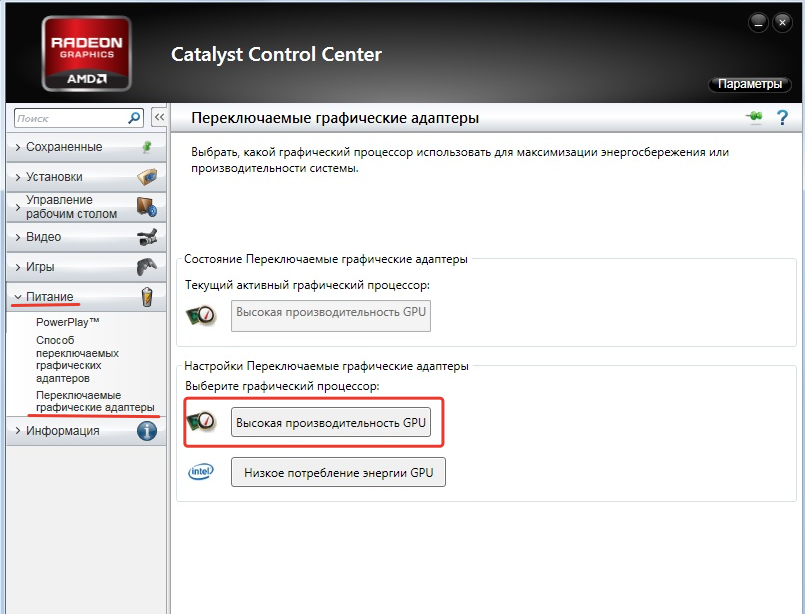 On alumina, the reaction starts at temperatures of 470-500°C, and when the contact contains 7.6 HbO, the temperature of the start of the reaction decreases by 70-100°C, which indicates a certain catalytic effect of the unreduced catalyst. The ignition temperature largely depends on the composition and method of preparation of the catalyst. [c.104]
The lowest temperature of a mixture of gas and air, at which the release of heat due to the combustion reaction of the gas somewhat exceeds the heat transfer, is called the ignition temperature. In this case, the excess of the released heat should not only cover the heat loss to the environment, but also be sufficient to activate the neighboring particles of gas and air and to heat them up to the ignition temperature. Only under these conditions is stable combustion of the gas possible. However, the ignition temperature of a fuel is a well-defined value characteristic of a given type of fuel. In practical conditions, it depends not only on the chemical composition and physical properties of the fuel, but also on a number of other conditions for the concentration of gas and oxygen, the degree of mixing of gas and air, the shape and size of the furnace space, the speed and methods of heating the mixture, gas and air pressure, as well as the presence of catalysts that accelerate or slow down the chemical processes of combustion. [c.47]
Catalysts have a very great influence on the autoignition temperature of liquids and gases. Catalytic properties can be possessed by the walls of a vessel in which a combustible mixture is located, or heated surfaces of a solid body, which is a source of ignition. Catalysts can also be introduced directly into the fuel. [c.89]
The temperature of the beginning of the abundant release of vapors, which can flare up when a flame is brought to them, is called the flash point. The flash point is much lower than the ignition temperature at which the fuel spontaneously ignites and, under favorable conditions, continues to burn on its own. For fuel oils and resins, the ignition temperature is on average 500-600°C; it noticeably decreases in the presence of catalysts and air enrichment with oxygen. The combustion reaction cannot continue spontaneously at ignition temperatures, and even more so at temperatures below the ignition temperature.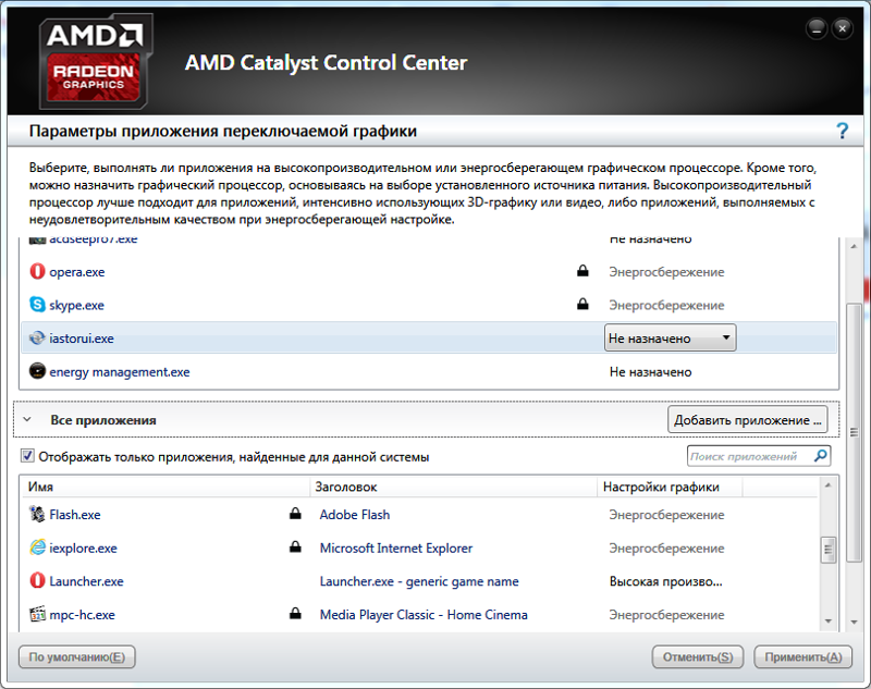 [c.28]
The second type of slow oxidation of combustible elements at temperatures below the ignition temperature is combustion on the catalyst surface. Although the catalytic combustion process can proceed quite intensively, it is still not a combustion process in the technical sense and may be of interest to heat engineers mainly from the point of view of its application for the selective combustion of gases for analysis purposes. [c.121]
In addition, during self-ignition in the volume of the unburned gas mixture, centers appear in which a self-accelerating development of a chain reaction occurs, leading to the ignition of the mixture. During this process, certain substances act as catalysts, and the addition of these substances in small amounts has a significant effect on the ignition temperature and ignition delay. However, such substances, for example, substances that promote the development of detonation in hydrocarbon fuels (positive catalysts) and antiknock additives (negative catalysts or inhibitors), do not cause a change in the burning rate (Table 7. 3, p. 145) [8]. Already on the basis of this fact, one can come to the conclusion that Gv by its nature differs from the self-ignition temperature. The reason why the reaction begins in the gas mixture layer adjacent to the flame front is apparently the diffusion of active molecules contained in the combustion products or in the reaction zone. Thus, the ignition temperature in the flame front Gw is not related to the self-ignition temperature. [c.138]
Many lead compounds are active catalysts that ignite carbonaceous materials. However, neither pure carbon nor lead salts alone have the ability to cause ignition [200]. The results of experiments to determine the minimum ignition temperature, compounds with carbon, partially [c.350]
So we see that for combustion to occur, it is necessary to heat the body to a certain temperature. It is called the ignition temperature. The ignition temperature of dry firewood is 300°, coal is about 400°, hydrogen is 650°, magnesium is 800°, etc.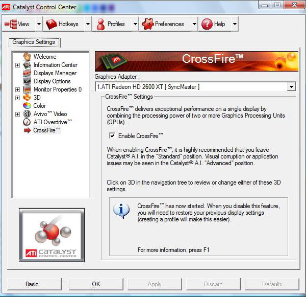 The presence of certain substances (catalysts) significantly lowers the ignition temperature. [c.209]
A special place is occupied by the so-called catalytic burners, which make it possible to burn gas at much lower temperatures than usual, through the use of materials that have a catalytic effect. Thus, for example, on infrared burners with a ceramic nozzle containing catalytic additives, it is possible to burn natural and liquefied gases at a temperature of 220-400°C, which is much lower than their ignition temperature. Hydrogen in the presence of catalysts burns at 150-300 ° C. At such low combustion temperatures, there is no need to dilute the combustion products with air in low-temperature processes, and nitrogen oxides are practically not formed. [c.286]
Hydrogen is a combustible gas; mixed with air, it ignites at a temperature of 510 °C. In the presence of a catalyst, such as spongy metals, the ignition temperature of hydrogen decreases.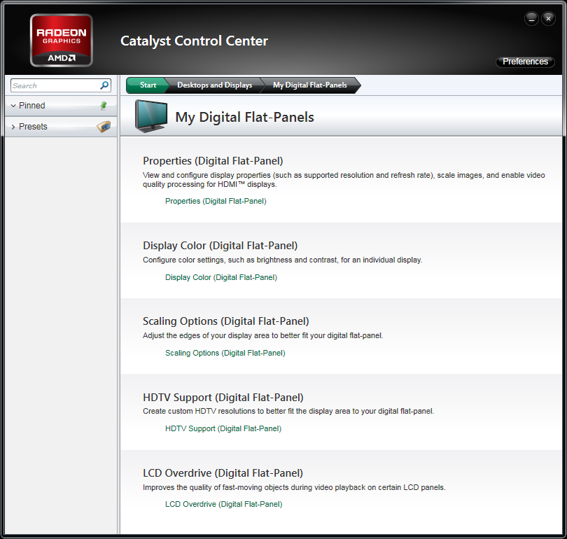 In production, such a catalyst may be a rusted or dirt-free surface of an apparatus or pipeline. When a mixture of hydrogen and air containing 4 to 75% hydrogen is ignited, an explosion occurs, which can cause damage and serious accidents. Such mixtures of hydrogen with air are called explosive. If there is less than 4 or more than 75% hydrogen in the air, when hydrogen ignites, an explosion does not occur, since in these cases a small amount of hydrogen burns out at the same time. [c.76]
The main advantage of hydrogen obtained by this method is the absence of foreign impurities in it, except for a small amount of oxygen. The oxygen content in the produced hydrogen is constantly monitored by automatic devices, signaling an increase above the permissible limit — 0.2%. If necessary, the oxygen contained in hydrogen can be removed by burning it in special electric furnaces in the presence of a catalyst that reduces the ignition temperature of hydrogen. [c. 77]
77]
Colorless oily liquid (molecular weight 152.19) with an ozone-like odour. Density 1.062, boiling point 60°C at 17 Pa (0.2 mmHg), decomposition temperature 4°C, flash point 80°C. Explodes at 170 °C. Soluble in organic solvents, slightly soluble in water. Under the action of acids and catalysts, it decomposes with the formation of equimolecular amounts of phenol and acetone. [c.233]
Oil mist and vapors of volatile fractions, together with the gas, enter the interstage communications and the discharge pipeline. Here, the oxidative process continues, and soot is also deposited on the walls of communications. The soot layer consists of elements that are intermediate products of oil oxidation, a large amount of fresh unoxidized oil, pipeline metal oxides, water and other impurities. At high air pressures and temperatures, as well as in the presence of process catalysts (water, metal oxides), the rate of the oxidation reaction increases. Since this reaction occurs with the release of heat, the soot is heated, which, in turn, causes a new acceleration of the oxidation reaction and an increase in temperature. In the end, the so-called spontaneous combustion of soot can occur. The latter is especially dangerous if the concentration of oil vapor reaches 32-40 mg l, which can lead to an explosion. Therefore, flash and ignition points are an important quality of oils. Both of these temperatures are determined by heating the oil in an open crucible. At the flash point, the mixture of oil vapor and ambient air above the mirror of the free surface of the oil ignites from the source of fire and immediately goes out. The ignition temperature under the same conditions will give oil burning for 5 seconds. [c.335]
Chain reactions i. Many catalytic reactions cannot be explained by a mere decrease in the activation energy under the influence of a catalyst. These primarily include those gas reactions that do not proceed at all in the absence of a catalyzing impurity (for example, moisture), reach a normal rate in the presence of traces of the latter, and do not noticeably increase their rate with an increase in its concentration.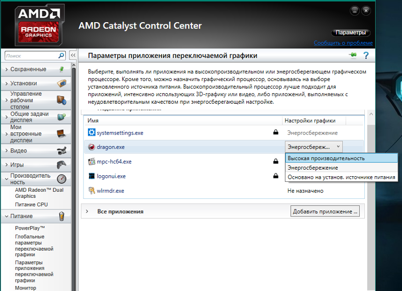 The number of reactions that completely stop upon thorough drying is large. the combination of chlorine with hydrogen in the light, the oxidation of NO and CO, the reaction NHg-j-Hl, a number of heterogeneous gas reactions, etc. A partial pressure of steam of water of the order of 10-10 mm Hg is sufficient. Art., so that these reactions go at a normal rate. Immeasurably small traces of ozone are sufficient to ignite a mixture of sulfur vapor with oxygen already at 50-100°C. The same traces of NO lower the ignition temperature of the mixture of H2 + O2 and O-j-Og by 50-200°. Compound h4 + I2 goes easily in the dark in the presence of a small amount of sodium vapor, etc. [c.476]
Preparation of the fuel surface is of great importance for the combustion process. Training. fuel oil, for example, consists in good atomization and mixing of its particles with air. The presence of catalysts (usually the walls of the furnace), which reduce the ignition temperature of the fuel, etc. , also has an effect. This process is called combustion. The process of successful combustion depends on the temperature of the fuel, the preparation of its surface and the effect of catalysts. For combustion to occur, it is necessary to heat the body to a certain temperature, called the ignition temperature, at which the heat developed during combustion exceeds the heat lost to the environment and which is sufficient to continue combustion. Combustion continues until the heat released [c.121]
This method allows you to avoid loss of varnish when painting objects with a small section. When applying varnish or enamel by electrostatic spraying, the electrical conductivity of the varnish plays a significant role. This method can only be used when the electrical resistance of the varnish is sufficiently high (not less than 10 Ohm-cm) and the ignition temperature of the varnish is sufficiently high (above 21 °C). To achieve these properties, solvents should be carefully selected; high-boiling non-polar solvents are most suitable. The presence of alcohols reduces the durability of the varnish, however, if the amount of alcohol is excessively reduced, the viability of the varnish with a catalyst decreases. [c.266]
Various additives can affect not only the rate of the gasification reaction, but also the pore size distribution and, probably, the type and number of oxygen surface compounds. Thus, when sodium compounds are used as catalysts instead of potassium compounds, the maximum in the pore distribution shifts to the region of large sizes. The formation of various surface oxygen compounds depends on the subsequent processing of activated carbon. For example, heating in air to temperatures slightly below the ignition temperature leads to the formation of acidic oxygen surface compounds. If air at room temperature is brought to activated carbon heated to high temperatures, basic oxygen surface compounds are formed. However, the maximum number of basic groups is definitely lower than the number of acidic groups. [c.50]
The ignition temperature determines the start of gas combustion, which depends not only on the physicochemical properties of the gas, but also on a number of external conditions (the degree of mixing of gas and air, the speed of heating the mixture, the pressure of gas and air, the presence of a catalyst), accelerating or slowing down the process, conditions of heat transfer to the environment, etc. [c.31]
and decrease the ignition temperature. The above is explained by the fact that the hydrogenation waste of vegetable oils contains nickel, which is a combustion catalyst. Characteristics of fuel briquettes are given in the table. [c.224]
Rare earth ions catalyze coke burnout coke on zeolite ignites at a temperature approximately 110°C lower than the ignition temperature of coke on a matrix without zeolite. Coke, even at a content of about 0.5%, significantly reduces the activity of zeolite-containing catalysts; therefore, the regeneration of such catalysts must be carried out at a coke content not exceeding 0.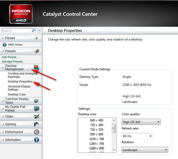 2%. [c.61]
The ignition temperature should be distinguished from the ignition temperature, at which the combustion of liquid fuel vapors begins spontaneously, without bringing the flame. For fuel oils, it is in the range of 500-600 ° C and decreases in the presence of catalysts, as well as when the air is enriched with oxygen. [c.44]
In the case of flame processes, the reverse heat conduction takes place directly through the reacting gas mixture, and not through the catalyst. (Reverse diffusion of free radicals is also important here.) If the reverse heat conduction is not strong enough, then the temperature of the cold gas entering the reaction zone is below the ignition temperature and it blows out the flame. [c.165]
The reaction start temperature (ignition temperature) also characterizes the activity of the catalyst. The operator of a sulfuric acid plant is interested in this property, since he knows that there is a certain critical temperature of the gas supplied to each adiabatic layer, below which the normal flow slows down and even stops. In addition, on catalysts with relatively low temperatures at the beginning of the reaction, the highest degree of conversion of raw materials and utilization of the released heat is achieved. Related to this is the special economic significance of the discussed property. Determining the reaction start temperature consists in finding the minimum temperature of the gas supplied to a certain catalyst bed, at which a mixture is obtained at the outlet, which is sufficiently close in composition to the equilibrium one. [c.259]
The monoxide formed during the oxidation of carbon can be further oxidized in the gas phase. Homogeneous oxidation of CO is a radical reaction with a branched chain mechanism [71, 72]. OH radicals play a fundamental role in the mechanism of this process. Therefore, the addition of small amounts of water vapor, hydrogen, or hydrocarbons to CO leads to a decrease in the ignition temperature of the mixture of CO and O by tens and even hundreds of degrees [71]. Unfortunately, the main studies of the process of carbon monoxide oxidation were carried out in the range of parameter values that are not typical for the conditions of the process of oxidative regeneration of the catalyst. [c.24]
V, V. Barelko, who, using the electrothermographic method, established the presence of such phenomena in non-stationary catalysis as the memory effect of the catalyst, the phenomena of vibrational instability, the nonuniqueness of the stationary states of the catalyst and the hysteresis effect. Perhaps the most interesting of these phenomena is the memory effect. Experimentally, it is found in the oxidation reactions of hydrogen, carbon monoxide, and ethylene on platinum. If in the experiment at the very beginning of the development of ignition (at the end of the induction period) by turning off the current, the sensor-catalyst is cooled and thus the process is interrupted, then during the subsequent heating of the sensor to the ignition temperature (even several hours after the operation of freezing - [c. 208]
208]
Thermal oxidation of gaseous pollutants can occur in the gas phase (in bulk) or at the interface (on the surface). The gas-phase process is carried out by direct fire treatment (burning in a flame) of gas emissions at temperatures exceeding the ignition temperature of the combustible components of the emissions. To organize the oxidation process at the phase boundary, catalysts are used — condensed substances capable of accelerating the oxidation process of a particular pollutant at temperatures below the ignition temperature due to the activity of surface particles. [c.411]
Frank-Kamenetsky [8] showed that for strongly erzethermal reactions with high activation energy the process is unstable in a certain temperature range of the catalyst surface. With a gradual increase in the gas temperature, starting from low temperatures, at which the reaction rate is very low, the temperature difference between the catalyst and the gas increases slowly at first, and then, upon reaching certain critical conditions (ignition temperature), immediately reaches the limiting value determined by the equation [19]at p — p», Similarly, as the temperature decreases, starting from a high temperature that exceeds the ignition temperature, the temperature difference between the surface of the catalyst and the gas at first changes little, and as it approaches certain critical conditions (attenuation temperature), it drops sharply.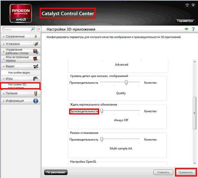 [c .412]
As the critical ignition conditions approached, the operating gas flow rate was set. ignition temperature, the steady state was not established — spontaneous, progressive heating of the reaction mixture was observed.The corresponding results of the experiment are shown in Fig. 1. [c.113]
The diffraction method also makes it possible to determine the gas temperature corresponding to the critical ignition temperature of the catalyst surface under various reaction conditions. The calculation is made according to the formula [c.116]
In order to reduce the consumption of air and natural gas, it is necessary to preheat the reaction mixture. The maximum heating temperature is limited by the ignition temperature of the gas. The ignition of the gas mixture in the volume, before it enters the catalyst, inevitably causes the precipitation of free carbon and a sharp rise in temperature, often leading to failure of the mixing devices. To determine the maximum heating temperature of the initial components, it is necessary to know the temperature of the beginning of the reaction of methane with atmospheric oxygen at a pressure of 30 at. [c.8]
KFU scientists have proposed an effective method for burning petroleum coke
To evaluate the effect of a catalyst on the ignition temperature, scientists began to work with a fixed fluidized bed.
In today’s world, in view of the widespread energy policy, one of the priority tasks of any state is to increase the efficiency of the use of fuel and energy resources and create the necessary conditions for transferring the country’s economy to an energy-saving development path. Responding to this trend, specialists of the priority direction «Econeft» pay more and more attention to petroleum coke, which is a waste product of oil refineries, and in terms of its quality characteristics surpasses many natural fuel resources.
The era when the final stage of oil refining was fuel oil used as fuel for ships and power boilers has come to its logical end. Today, fuel oil is processed more efficiently, «squeezing out» it to the last hydrocarbon, leaving only a solid residue — petroleum coke. Now scientists are faced with an acute task — to create a technology that will allow it to be processed as efficiently and environmentally safe as possible. In the meantime, petroleum coke is stored in increasing quantities underground and on its surface, as well as in numerous landfills. Burning petroleum coke is extremely difficult.
“Petroleum coke is difficult to combust, also because of its graphite-like structure. Graphite itself burns from 700 °C. The ignition temperature of petroleum coke, depending on its composition, can start from 450 °C. It is difficult and economically unprofitable to achieve such a temperature. To reduce its ignition temperature, it is necessary to use catalysts, ” — explained researcher at the Rheological and Thermochemical Research Institute Emil Saifullin .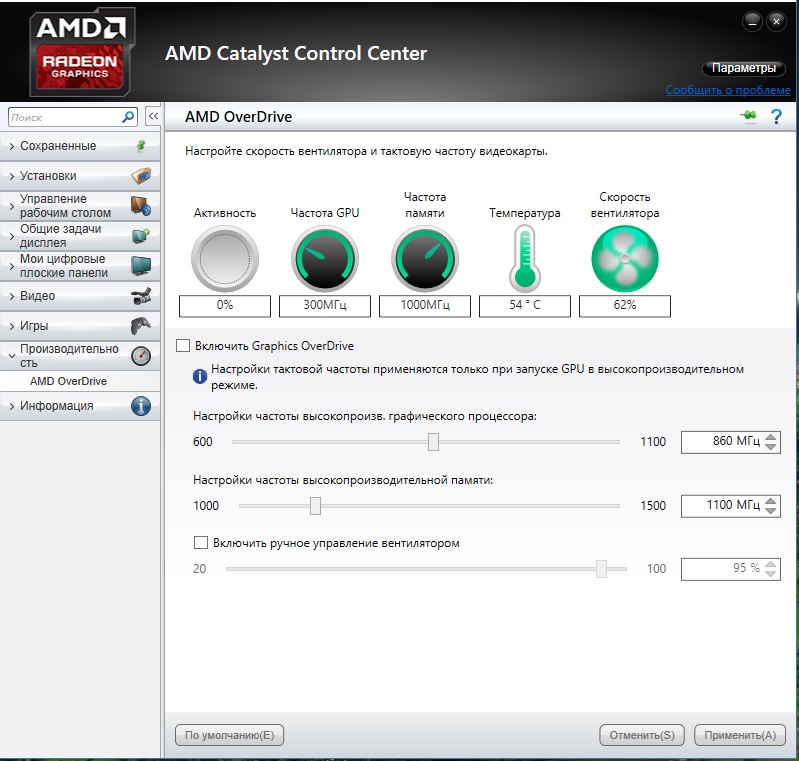
In one of the latest studies, KFU scientists examined the kinetics of combustion and oxidation of petroleum coke in the presence of metal catalysts. To evaluate the effect of the catalyst on the ignition temperature, the scientists proposed a new approach to working with a fixed fluidized bed. The results of the study were published in the journal ACS OMEGA.
“It is also difficult to achieve complete combustion of petroleum coke. Fluidized bed combustion technology is commonly used to combust this kind of particulate matter. In its traditional form, a fluidized bed is a way of creating the most suitable conditions for a chemical reaction. In this case, for the combustion reaction. The technology is to make every single particle fly right in the air. For example: if we take a fine sieve and pour charcoal powder on it, supply air through the sieve from below, then pieces of the powder will fly up and separate from each other into thousands of particles. The main goal is to organize the greatest contact of air with the substance so that the combustion process goes better”, — the scientist explained the essence of the work of the fluidized bed.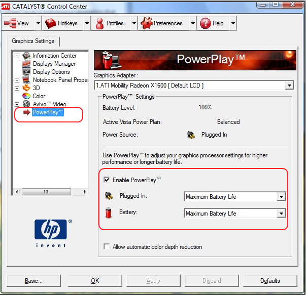
For substances that are difficult to combust, such as petroleum coke, this technique is an effective solution, the researcher believes.
The second problem with petroleum coke disposal is its unique composition: it contains all the metals found in oil. «Black gold» is a unique fossil, representing almost the entire periodic table. Therefore, petroleum coke is the concentration of everything that was in oil, including metals that unpredictably affect the combustion process.
The use of fluidized bed technology is actively used in the industry of foreign countries, but it is still a novelty for the Russian power industry. KFU scientists considered this technology as a promising method for burning petroleum coke, but for a qualitative comparison of combustion catalysts, the fluidized bed must be “frozen”. To do this, the researchers separated the particles of petroleum coke by mixing them with quartz sand. In such a «frozen» mode, scientists can accurately and most closely to real conditions study the kinetics of combustion of petroleum coke and the effect of catalysts on the ignition temperature.
The result of the experiments carried out is the creation of a new method for studying the combustion of petroleum coke and finding effective catalysts that will achieve positive results for the energy sector.
Samara scientists have developed renewable catalysts for the petrochemical industry / Interfax
Scientists have succeeded in increasing the activity of nickel catalysts, which are usually used in industrial enterprises, by modifying mesoporous silica gel with a small amount of rare earth elements — dysprosium and lanthanum.
Thus, in the course of the experiments, effective catalysts based on mesoporous silica gels were synthesized, among the advantages of which experts name lower levels of operating temperatures and pressure, high conversion and renewability of the catalysts used.
«The aim of our research was to increase the catalytic activity of the catalyst by incorporating a small percentage of dysprosium or lanthanum. In this case, the total nickel content can be reduced, which makes the catalyst cheaper. In addition, new catalysts allow the hydrogenation reaction to be carried out at lower temperatures and pressure, that is, enterprises will be able to reduce the cost of products by reducing energy consumption for their production, which will make hydrogenation processes more economical and environmentally safe. For the Samara region, these developments are very important, since hydrogenation processes are widely used at chemical, petrochemical and oil refineries in the region, «- the message contains the words of the project manager, postgraduate student of the Department of Physical Chemistry and Chromatography Elena Tokranova.
It is clarified that the catalyst based on mesoporous silica gel doped with dysprosium and modified with nickel turned out to be the most effective of those developed. Its working temperature is 150 degrees, pressure — 3 atmospheres, hydrogenation time — 20 minutes. For comparison: a typical nickel catalyst used at enterprises on a highly dispersed carrier has an operating temperature of 250 degrees, a pressure of 20 atmospheres, and a hydrogenation time of 30 minutes.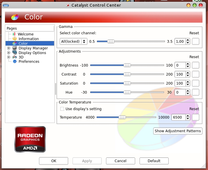
Work on the project for the creation of new catalysts for the selective hydrogenation of aromatic hydrocarbons was carried out by members of a scientific group led by Angela Bulanova, Professor of the Department of Physical Chemistry and Chromatography, within the framework of a project supported by the Russian Foundation for Basic Research.
Read Interfax-Obrazovanie on Facebook, VKontakte, Yandex.Zen and Twitter in catalysts
Author profile
I was driving down the highway and the car lost power. It’s good that it didn’t happen while overtaking.
I got to the nearest car service and removed the catalyst. Then he paid for the work and left everything that was left of this catalyst to the guys from the car service. Then I did not know yet that this part contains precious metals and they give good money for everything that is left of it. Next time I will be smarter: I will drive the car up to 100,000 km, then I will remove it, and I will keep the catalyst or pay them for their work.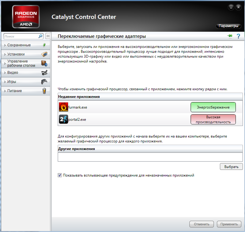
Because of these stories, some car owners consider the catalyst a time bomb and rush to remove it as soon as possible. Some car services are happy about this and advise removing catalysts even on new cars. They argue that this is an extra detail that environmentalists impose on automakers, and that the car will then drive more cheerfully, and fuel consumption will decrease.
I tried to figure out how much the catalyst is an extra part in the car and whether it can be removed. From this article, you will learn how a catalyst works, what types of catalysts are, why they fail, and what are the signs of a faulty catalyst.
The catalyst is located in the exhaust system of the car, closer to the engine exhaust manifold, and is needed to clean the exhaust gases from harmful emissions. Source: Setta Sornnoi / Shutterstock
What is a catalyst and why is it needed
An internal combustion engine runs on an air-fuel mixture.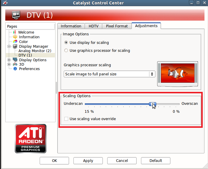 It burns out with the formation of toxic exhaust gases, and on gasoline engines, some part of the mixture may not burn at all and fly into the exhaust pipe. In order to somehow reduce the concentration of harmful substances in the exhaust gases, they put an exhaust gas catalytic converter in their path: a catalyst, if in a simple way. Exhaust gases go through it, like through a filter.
Technically, this is a refractory ceramic or metal cylinder with honeycombs through which exhaust gases pass, which contain harmful substances: hydrocarbon, nitrogen oxide, carbon monoxide. On the walls of these honeycombs there is a microlayer of catalyst substances: it can be platinum, palladium or rhodium. They speed up chemical processes, and exhaust gases after redox reactions with these metals become less toxic.
Cells of good ceramic catalyst. Source: Anton Tolmachov / Shutterstock
Catalysts are mainly installed in the exhaust system of cars with gasoline engines. There may be several of them: for example, if two separate exhaust pipes come from the engine, they put one for each. It happens that catalysts are installed in series on one exhaust pipe.
Diesel particulate filters are most often used to treat diesel exhaust gases. The design is approximately the same, only the filter cells are closed on one side. Exhaust gases find their way out through the porous walls of the channels, on which soot settles. These filters need to be cleaned periodically. To do this, the temperature inside the filter rises, and the soot particles burn out. This process is called active regeneration.
Another catalyst reduces the temperature of the gases. For example, at the inlet to the catalyst, the gas temperature is about +390 °C, and at the outlet it is already +260 °C. Approximately in this temperature regime, chemical reactions take place, therefore, for some time after the engine is started, the catalyst does not work.
NEW COURSE
How to make repairs and not go crazy
Understanding how to start and finish repairs without overpayments: from design to acceptance
Show me!
Whether the catalyst works or not is determined by the second oxygen sensor, also known as the lambda probe. It is placed after the catalyst, and its task is to determine the level of toxicity of emissions. If you simply remove it, the sensor will record the low efficiency of the catalyst, and a Check engine error will appear on the dashboard.
There are different emission classes for vehicle emissions: Euro 2, Euro 3, Euro 4, Euro 5 and Euro 6. Since 2016, the Euro-5 standard has been in force in Russia for new cars. You can find out the environmental class of your car in the vehicle passport. According to the experience of car service workers, the higher the environmental class of the car, the less the catalyst resource. The walls of the ceramic honeycomb of such catalysts are thinner, the cells are denser to work more efficiently.
The environmental class is specified in the 13th paragraph of the vehicle passport
Types of catalysts and their substitutes
The original catalyst is installed by the manufacturer.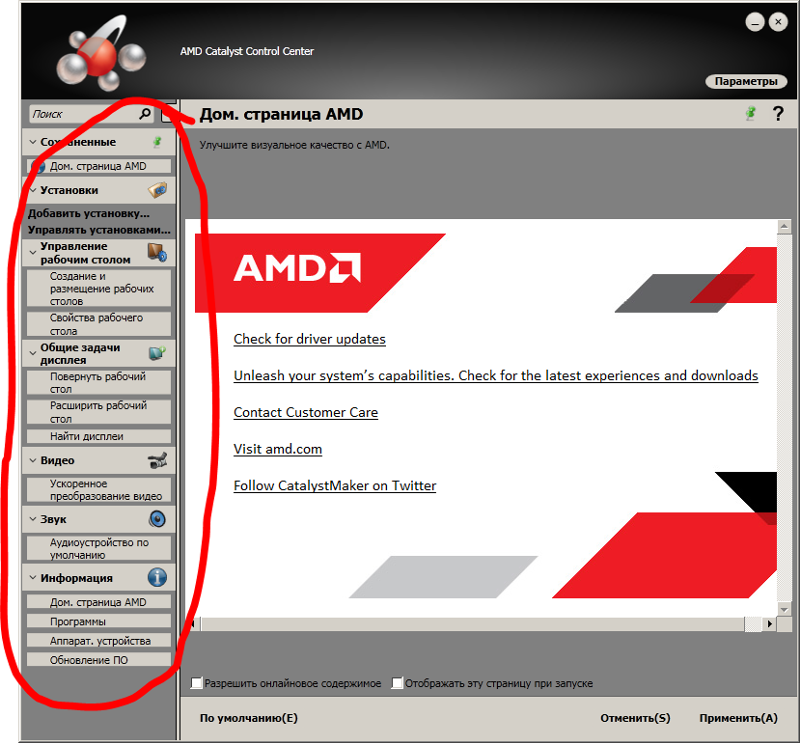 This can cost up to 5% of the cost of the entire car. There are few enterprises for the production of catalysts in Russia. They are mainly made abroad, their cost depends on the state duty, the dollar exchange rate and the exchange rate of precious metals. Replacing a catalyst with an original one costs from 25,000 rubles.
Usually, such a replacement is done on warranty cars if for some reason it has failed or been stolen. The service life of the original catalyst is usually not less than the warranty period of the car.
The price of a new original catalyst for Hyundai Solaris 1.6 l 2017 is from 58,000 R
Universal catalyst replaces the original one for almost any car. It costs less than the original one, and its service life is shorter. In theory, it should last about 60,000 km. Prices for a universal catalyst start from 5000 R. In the cells of such catalysts, instead of platinum, palladium and rhodium, for example, gold is used.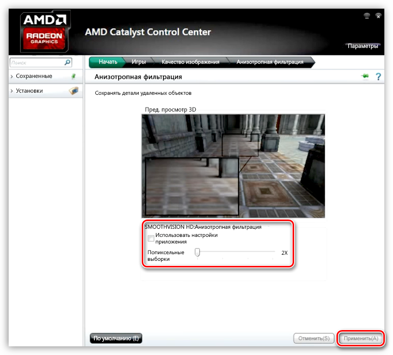 It accelerates catalytic reactions worse, therefore it cleans exhaust gases from harmful substances worse.
When choosing a universal catalyst, it is important to correctly determine its volume, which should not be less than the original one. The catalyst body is not always round, it has different lengths and widths. The spent catalyst is cut out of the housing with a grinder, and a new one is welded in its place. It is better that these works are carried out by an experienced welder who will make a high-quality weld.
Installation of a universal catalyst is a compromise for those who do not want or cannot buy an original catalyst, but care about the environment or at least want to pass an inspection.
Euro-5 universal metal catalyst. Installs in place of the old catalytic converter
Flame arrester in English exhaust repair manuals is the «pre-silencer». It mixes exhaust gas flows from different cylinders, reduces their temperature, and also reduces noise and vibration to an acceptable level. It is installed instead of a catalyst, but it does not affect the toxicity of exhaust gases in any way.
If the flame arrester is not installed after the catalyst has been removed, the exhaust system will eventually burn out due to the high temperature of the exhaust gases. A simple flame arrester is a pipe with perforations for gases in a steel case. Prices for flame arresters start from 760 R.
A refractory filler is laid between the body and the flame arrester tube. Usually it is basalt, synthetic fiber or mineral wool. The body of flame arresters can be single-layer or double-layer. Two-layer is also called reactive. They are more durable and dampen sound wave vibrations well. The inner layer must withstand high temperatures, and the outer layer must withstand corrosion.
For each vehicle, you need to calculate the optimal volume of the flame arrester. If the volume of the flame arrester is not enough, then the sound at the output will be unpleasant, rattling. Those elements of the muffler that are located after the flame arrester are subject to increased wear and fail faster.
Compared to the cost of the original catalyst, it is cheaper to install a flame arrester — from 3500 R. Its installation involves flashing the engine control unit (ECU) or installing a special «trick» for the electronic control unit. We will write more about them below.
Perforated pipe and refractory filler inside flame arrester. Source: CameraMan32 / Shutterstock
Can the catalyst be removed
By default, the catalyst is designed to last the life of the vehicle. But fuel quality and harsh operating conditions destroy it much earlier: for example, at a run of 100,000 km.
There is no universal or regulated catalyst removal time — each case is individual. A faulty catalyst causes many problems: from an annoying Check engine light to ceramic dust getting into engine cylinders. Therefore, in most cars older than ten years, the catalyst has already been removed.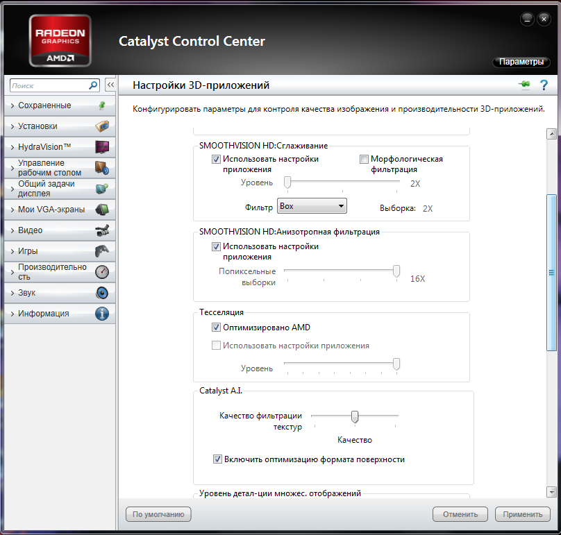
There are exhaust systems where the catalytic converter is very close to the engine. In the case when it begins to collapse, dispersion dust from it flies towards the engine. It is very fine and hard, it can be compared to fine sand. It scratches the engine cylinders when the pistons work. Due to these scratches, the engine starts to consume oil or its consumption increases — this is the case if the engine consumes it from the first days of the car’s operation.
Sooner or later, this leads to an overhaul of the engine. Some car owners want to avoid such unpleasant consequences and remove the catalyst even before it starts to break down.
Replacing a catalyst with a new one is an expensive procedure: one catalyst can cost 100,000 R, and now imagine that there are two of them in the car and both have worn out about the same. Therefore, instead of a new catalyst, a flame arrester with a «trick» or, much less often, a universal catalyst is most often installed in the exhaust system.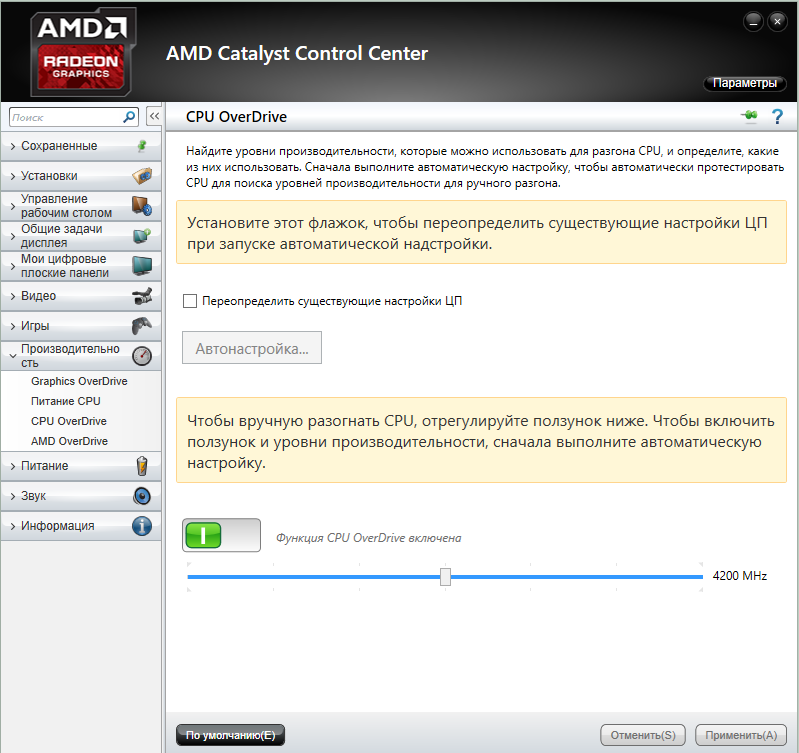
Inside the blende is a small piece of catalyst. It is put on the second lambda probe, and part of the blende with the mesh is screwed into the exhaust system after the flame arrester. Thanks to the device, the car’s ECU thinks that the exhaust gases are in order, the catalyst is in place, and the Check engine on the dashboard does not light up. Nevertheless, the snag does not guarantee that the error will not appear: the light may light up after refueling with not the best gasoline or after a sharp acceleration
Fake for the second lambda probe
You can do without trickery. To do this, you need to reflash the electronic control unit and configure it so that the lambda probe perceives new «harmful» sensor readings as the norm. In the advertisements, this procedure is called a flashing for Euro-2 and they promise that the car will drive more cheerfully, the engine will produce 20-30 horsepower more.
At the same time, any interference with the original ECU software is a risk, so a qualified specialist with a proven program should do the flashing. When installing a flame arrester, car exhaust gases are not actually cleaned, but the Check engine error on the dashboard will not appear due to flashing. It is very important to remember that despite this, the engine was most likely designed for a higher environmental class, which means that with Euro-2 settings it will work much less than it could.
Installing decoys, flame arresters instead of a new original catalyst can lead to unexpected consequences: engine errors, bad exhaust smell or excessive fuel and oil consumption.
Due to the fact that the amount of harmful emissions from such repairs does not meet the declared standards, the car may not pass the inspection. According to Russian law, a catalyst is a component of a vehicle, so the car owner removes it at his own risk. If for some reason you need to replace the original catalyst, then installing a universal one is the best solution.
I do not advise you to remove the catalyst on warranty cars with a mileage of up to 100,000 km without the need.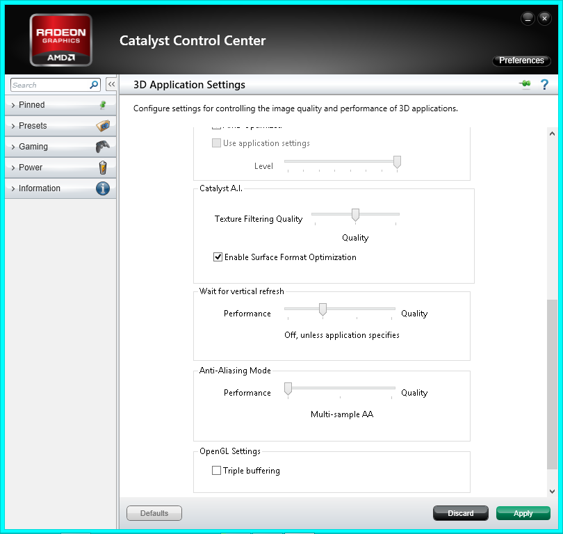 The car engine will most likely be removed from the warranty due to interference with the exhaust system. On warranty cars, a problem with catalysts rarely occurs, less than 1% of cases of total sales.
The diagnostic equipment deciphered the Check engine error on the dashboard. The problem is in the catalyst
Why catalysts are stolen
Car sharing cars and taxis often suffer from catalyst theft. But there were cases when the original catalyst was cut out on the street when the car was parked overnight in the yard. It is enough to raise the car with a jack and cut out part of the muffler with a grinder.
In vehicles with high ground clearance, the catalytic converter can be reached even without a jack. Catalyst theft takes about a minute. But if the alarm is equipped with a tilt sensor, then it will report that they are trying to raise the car.
Catalysts are stolen in such a barbaric way: they simply cut it out with a grinder. Source: Konstantin Gakhov / Vkontakte
The catalyst can also be cut out in an unscrupulous car service. The owner is offered to “clean out” the exhaust system or remove a serviceable catalyst so that it does not cause problems in the future. Employees of such car services also talk about the benefits of removing the catalyst: they promise that engine power will increase and fuel consumption will decrease — ECUs are sewn for Euro-2. If we evaluate the real increase in power on special equipment, the increase will be insignificant — only 3% of the initial figures.
Usually, car services do not charge for removing the catalyst, installing a flame arrester, decoy or flashing the electronic control unit, but simply keep the spent catalyst for themselves.
But there are a lot of those who simply take it silently, without any discounts and payments, like scrap metal. And then they hand it over, because the original catalyst contains precious metals that cost more than gold.
On average, precious metals are 0.08-0.17% of the total mass of the catalyst. Over time, it develops its resource and there are fewer precious metals. The exact amount of platinum, palladium and rhodium in a particular catalyst is determined by a precious metal analyzer.
If they ask you to pay for the removal of the catalyst, the installation of a flame arrester, then I recommend that you keep the catalyst. Not only the whole catalyst is of value, but also the destroyed one, its scrap, crumbs and even dust. For a worn-out catalyst of a modern Euro-5 standard car, you can get from 5000 RUR. The more powerful the car engine, the more fuel it consumes, the better, and therefore the more expensive its catalyst.
Price of platinum, palladium and rhodium per gram in rubles. These metals are most likely in the original catalyst of a car with a gasoline engine
Cause of catalytic failure
Precious metal coating wear.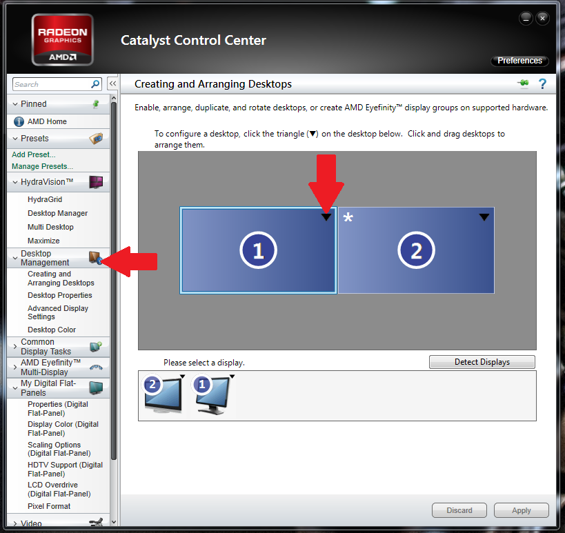 Precious metals on the walls of the catalyst cells burn out — this is a natural process. Therefore, when a catalyst is accepted for processing, its chemical analysis is carried out. It may turn out that there are no precious metals left in the catalyst at all. When this happens, the exhaust gases stop cleaning, the oxygen sensors detect this, and an error occurs on the instrument panel.
Low-quality fuel. Sometimes, to increase the octane rating of fuel, unscrupulous gas station owners add additives that contain lead to it. This increases the load on the catalyst, the cells become clogged with fuel combustion products, and it fails earlier. For diesel engines, increased wear of the particulate filter occurs in winter when anti-gel is added to the fuel.
Ignition faults. If the spark plugs spark intermittently, then the unburned fuel-air mixture is burned in the catalyst, which reduces its service life. At the same time, the catalyst cells melt, and its throughput decreases.
Engine malfunction. If there are scratches or scuffs in the engine cylinders, then the mixture that is obtained during the operation of the internal combustion engine ceases to be two-component — that is, it now consists not only of air and fuel. It also contains motor oil. This inevitably clogs the catalyst, and it soon fails. Often a failed catalyst is blamed for engine problems. But in this case, rather, the engine provokes problems with the catalyst.
A defective catalyst may melt, break down, or become clogged. Source: LuYago / Shutterstock
How to spot the problem
Catalyst rarely fails suddenly, in one moment. Usually this is preceded by typical symptoms of the engine, exhaust system and extraneous sounds. If you carefully analyze all the changes, you can intervene in time and correct the situation.
The check engine light on the instrument panel lights up for various reasons.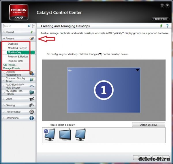 If we consider the code as a special scanner, then it will show exactly where the problem arose. An error in the catalyst air sensors indicates that something is wrong with the catalyst.
Reduced engine power. It feels like driving a trailer or a car in tow. The car starts off, accelerates, but something seems to interfere with it — the acceleration is not energetic enough. Sometimes the engine of the car vibrates, and the car itself twitches.
Extraneous sounds under the bottom. If the catalyst has already begun to break down, then its particles at high engine speeds or during start-up hit the exhaust system housing. At the same time, the driver hears extraneous sounds under the bottom of the car. They are like a ringing sound in an empty metal can.
Unstable gas pressure from muffler. For such a check, you need to put your hand to the exhaust pipe and feel the beat of the exhaust gases. During normal operation, gases are released at regular intervals, similar to the beating of the heart. If the flow of gases is even and weak, then the catalyst is most likely defective.
Exhaust smell. If the catalyst does not clean the exhaust gases from toxic emissions, then this can be felt without special measurements of carbon dioxide levels. Next to the car, especially at the time of its warming up, it will be unpleasant to smell the products of combustion of the fuel-air mixture. Sometimes the smell enters the car interior when the engine is idling.
Seizures on the cylinders. If the catalyst has already begun to break down and its particles have entered the combustion chamber of the fuel-air mixture, then scoring and scratches form on the cylinders. Their condition can be checked in a car service with a special device — an endoscope. If everything is in order with the cylinders and there are no other signs, then it is not necessary to remove the catalyst.
Endoscope test. It is possible to launch the endoscope through the hole for the first lambda probe.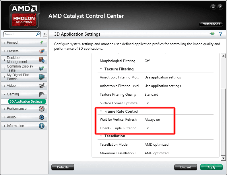 Ceramic honeycombs must be of the correct shape, without dents, not melted, not destroyed or clogged. We have already figured out that the second oxygen sensor is located after the catalyst, which means there is nothing to look at there: it is highly likely that the cells will be in perfect order at the output.
Sensor diagnostics. With the help of an autoscanner, for example ELM 327, you can connect to the car’s electronic control unit. In smartphone applications, you need to select the readings of the catalyst oxygen sensors and compare their actual values with the reference ones.
The sensors must be checked with the engine warm and idling. Deviations from the norm will mean that the catalyst is faulty. Although it also happens that the matter is in the second oxygen sensor — they burn out over time and stop working, so it would be useful to combine this method with an endoscope check.
Checking the catalyst with an endoscope shows that there is no damage to the cells Screenshot of the application for the ELM 327 scanner. I checked the oxygen sensors of my car — Hyundai Crete. How to read these graphs — I learned from the video on YouTube. The top graph shows the readings of the oxygen sensor before the catalyst, and the bottom one — after it
Remember
- The catalyst is an important part of the exhaust system that cleans the exhaust gases from harmful emissions.
- If the catalytic converter is defective, the engine loses power, extraneous sounds appear in the exhaust system, and the exhaust gases smell unpleasant.
- The catalyst fails prematurely due to low-quality fuel, ignition and engine malfunctions.
- Diagnostics of the computer with an autoscanner or a visual check of the cylinders and catalyst with an endoscope will help to detect the problem.
- The original catalyst contains precious metals, which is why it is so expensive.
- If you need to replace a spent original catalyst, it makes sense to install a universal one.
- Installing flame arresters, decoys and flashing the ECU can lead to engine problems.

- Do not remove the catalyst unnecessarily on warranty vehicles.
- Catalyst removal can be paid for with old catalyst. Paying for work and leaving the catalyst in the service as scrap is like giving money as a gift.
- Unscrupulous car services offer to remove the catalyst in order to turn it in and earn money.
FK-100 | Catalysts | Products
Designed to meet business and technical needs, the FK-100 Formaldehyde Catalyst provides a unique combination of high internal selectivity, excellent stability and operational flexibility. Take advantage of our tailor-made loading schemes and recommendations for plant optimization and you will see why the FK-100 is the most attractive formaldehyde catalyst on the market today.
9,000 iron, which can significantly reduce the formation of CO and DME by-products. All this, combined with an optimized structure, shape and composition, provides exceptional selectivity and
yield typically greater than 93% at 98.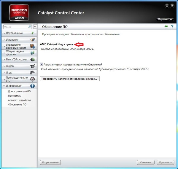 5% conversion.
Long Catalyst Life
Optimization of production technology and composition allowed us to reduce the temperature of the hottest spot of FK-100 by 15–20 °C compared to previous generation catalysts. The lower hot spot temperature ensures consistent temperature profiles across the catalyst tubes and minimizes catalyst degradation, which reduces the rate of pressure drop and extends catalyst life.
Operational flexibility
The FK-100 catalyst easily handles the significant fluctuations in humidity, ambient temperature and methanol flow that a plant can experience, thereby increasing flexibility while reducing plant downtime.
Loading and Optimization Recommendations
In order to maintain optimum reactor performance, your loading pattern and operating parameters must take into account plant operating conditions and product requirements. Topsoe’s engineers are always available to help you optimize your loading pattern to meet your special requirements, as well as take over the supervision function during loading.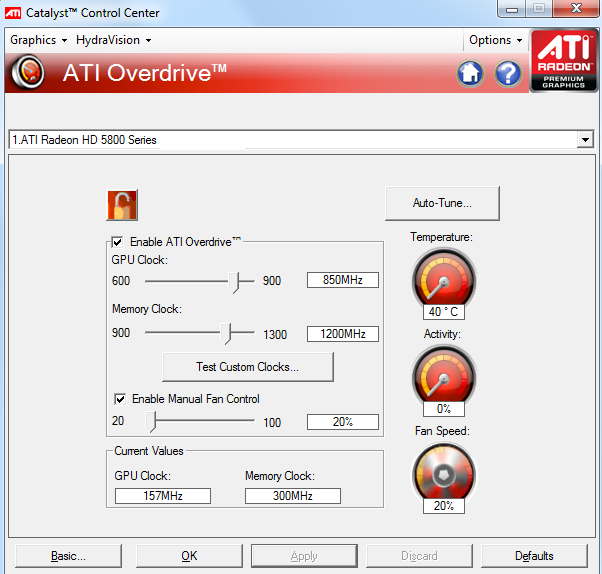
Catalyst
— how to use it correctly? • AutoCentrum.pl
The catalytic converter, also known as the catalytic converter, is an important part of the exhaust system found in almost all modern cars. Its main task is to reduce the harmful compounds of the combustion process that could enter the atmosphere. These are mainly: carbon monoxide (CO), hydrocarbons (CH) and nitrogen oxides (NOx).
How does it work?
The operation of the reactor is based on the chemical reaction of compounds contained in exhaust gases with a catalyst, which is rare metals (eg iridium and platinum), sealed in a metal can. In gasoline engines, so-called. three-way catalysts known as TWC (Three Way Catalyst). Their name comes from the simultaneous reaction with three groups of harmful compounds: these catalysts reduce both nitrogen oxides and oxidize hydrocarbons and carbon monoxide. The situation is different for diesel engines.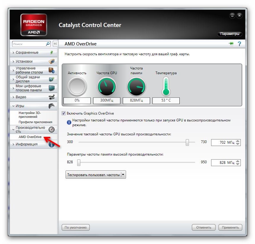 As in gasoline plants, reactors oxidize CH and CO compounds, but do not reduce harmful nitrogen oxides. The latter are reduced by exhaust gas recirculation in the engine itself. The so-called solid particles (soot), the amount of which can be reduced by recharging.
When does it work?
The catalytic converter does not work immediately after starting the engine: the minimum temperature at which it begins to restore harmful substances in the exhaust gases is about 300 degrees C (catalysts are placed as close as possible to the exhaust manifold so that they heat up quickly). turn, the proper operating temperature is about 800 degrees C. In the latest models of cars, two catalysts are used: the first works in the so-called cold start, the second during normal engine operation.
What breaks?
On average, the catalyst retains its properties up to approximately 100,000 km (in some cases, the service life of the catalytic cartridge can be much longer). On the other hand, negligence resulting from the lack of technical inspections and mechanical damage contribute to a significant reduction in its service life. In the first case, among other things, o oil or coolant that has entered the exhaust system, and in the other, to the rapid cooling of the catalyst (for example, after driving into a deep puddle on the road) or damage as a result of, for example, a sudden impact on a high curb. In diesel engines, the problem with the catalytic converter can also be associated with its obstruction. Why? Units with a diesel engine emit more particulate matter, which increases the likelihood of catalytic converter clogging. In order to assess the permeability of the catalyst, a measurement of the so-called exhaust gas back pressure is carried out when the engine is idling.
Catalyst and LPG
In a properly operating gas plant, the propane/butane mixture will not adversely affect the catalytic system. The oldest generations of LPG installations can present a problem without electronic gas-air mixture control. These installations use a mixer (so-called Venturi nozzle) and its regulating properties determine the composition of the exhaust gases, which in many cases is impractical. As a consequence, this leads to a rapid decrease in catalytic properties and damage to the reactor itself.
.
The correct temperature of the catalyst
Magdalena Serafin
January 7, 2021
TECHITION TIME: 2 minutes
Evaluate: / Current Rating: 5
It is assumed that the correct temperature of the catalyst is in the range from 600 to 800 degrees Celsius. It is this value that allows our catalytic converter to most effectively reduce the content of pollutants in the exhaust gases of our car. It often happens that we have a problem with this component, and the diagnosis sounds like the catalyst temperature is too high. This often happens when we refuel the car with poor quality contaminated fuel. What if low catalyst temperature is our problem? In addition, this situation will make it difficult to reduce the amount of harmful exhaust gases coming out of our exhaust system, due to the lack of the necessary conditions to start the process. As you know, this requires a fairly high calorific value.
1. What temperature should the catalyst be?
Catalyst temperature must be optimized. If it is too high, it is not difficult even to melt the cartridge. This is very common with contaminated fuel, causing the temperature in the catalytic converter to often reach over 900! So, we can imagine how our tender component would react to such a sudden change. Regardless of whether the temperature is too high or too low, we should contact the service center as soon as possible, where we will definitely be helped. Don’t delay or wait for a bad catalytic converter to destroy other components!
Correct temperature of the catalyst
New catalyst
Considering the above problem, it is worth noting that the catalyst is subject to regeneration, cleaning and possible replacement of the damaged element. Depending on the factor that caused this abnormal temperature. There is no need to buy a new component. Proper regeneration and cleaning, as well as symptom diagnosis and a visual inspection of the catalytic reactor before this event, can restore the correct temperature of the catalyst and save us the cost of acquiring a completely new component. As an encouragement, let’s add that he will not show any differences in his work compared to the one that came straight off the assembly line.
New Catalyst
Magdalena Serafine Emissions Control Editor
Highly qualified specialist in solutions used in diesel emission control systems. Passionate about motorsports and Mediterranean cuisine. Mountain tourist. Author of many studies on the design and operation of particulate filters and DPF FAP catalysts, including the SCR system.
Share
.
How hot is the catalyst?
Kamil Mila
January 18, 2021
Text reading time: 2 minutes
Rate: / Current rating: 5
In the context of an emission control component, many specific questions arise, one of which is in the title of the article: to what temperature does the catalytic converter heat up? The parameter that is the correct temperature of the catalyst is between 400 and 800 degrees Celsius, such a high level of heating of the component is necessary for the optimal performance of the catalytic processes occurring in this component. However, it is worth knowing that the device begins to perform its functions only from the moment it reaches its operating temperature, which is 300 degrees Celsius. In addition, its flawless operation is also associated with the flawless functioning of the lambda probes, which check the optimal percentage of air in the exhaust gases. The temperature to which this catalyst is heated depends largely on the user of the vehicle. Of course, every owner should want a part to last as long as possible, and as long as possible, but the obvious savings in the form of cheaper fuel, and high temperature of the catalyst, or other potential breakdown of the car are tempting. associated solely with the use of low-quality fuel, cover a few zlotys left in the wallet. However, below we have written what needs to be done to extend the life of the catalytic converter.
How hot is the catalyst?
How to care for the catalytic converter?
The question of catalytic converter care regularly arises among the requests of our customers.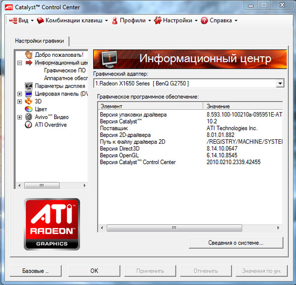 The quality of the fuel being filled has a significant impact on the life of this unit, and exhaust gases from a heavily contaminated fluid will quickly fill the catalyst, which will affect its patency. This is worth paying attention to, especially if you have a diesel engine, as diesel exhaust gases contain more pollutants. Another problem is associated with mechanical damage associated with the location of the assembly and the design of the catalyst, where rapid cooling of its body or hitting a high curb can lead to the destruction of its liner. Regular technical inspections will also affect the condition of the catalyst, allowing you to effectively check its current condition.
How to care for the catalyst?
Camil Mila Expert in diesel particulate filters
<br> Specialist in DPF, FAP and SCR catalytic converters. Privately motorization fanatic.
Share
.
Car Catalyst Failure Symptoms — Kaliński
Catalysts are very important elements in our cars, their function is to neutralize harmful compounds formed when using cars with internal combustion engines. Due to their function, catalytic converters are installed on all modern cars. It is important to maintain catalytic converters in good condition and be able to correctly assess the symptoms of a failed automotive catalytic converter. Early identification of catalytic converter problems will allow us to react quickly and possibly prevent further breakdowns or immobilization of the vehicle.
A damaged catalytic converter is a serious problem in our vehicle that can lead to vehicle immobilization. «The catalytic converter is damaged, what are the symptoms» is a question worth investigating. A catalyst, also known as a catalytic converter, is one of the elements of an off-engine exhaust gas purification system. Catalysts, which gained their importance after the introduction of restrictive regulations related to the reduction of harmful compounds, are now installed in every car with an internal combustion engine.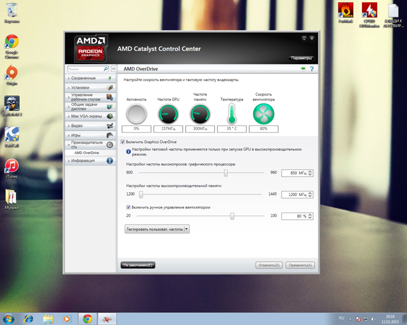 Catalysts are located under the car, but can also be integrated with the exhaust manifold or bolted to the turbocharger. Very often catalysts are also integrated with DPF filters.
Causes of catalytic converter failure
Catalytic converters are special elements of our vehicle. The way it is used has a great influence on the performance of the catalyst. The catalyst is much more often used in the mode of operation characteristic of driving outside the city, then it has a chance to self-heal. Self-regeneration allows you to clean the catalyst and restore its proper permeability. Catalysts and other elements in cars are damaged or fail. But what could be causing this?
High temperature operation is the natural environment for a catalytic converter. The catalyst is located very close to the engine and therefore reaches a temperature of around 500-600 degrees Celsius. Failure can occur, for example, when the catalyst is suddenly cooled. A sudden change in temperature can cause a crack in the catalyst housing or damage to the liner. Sudden cooling can occur when driving through puddles or on contact with snow or ice.
Catalysts need high temperatures to work properly. The problem may be that the operating temperature is too low to burn the residues formed during the combustion of the fuel, the catalyst must be warmed up. If the catalyst is operated too often at low temperatures, it will not regenerate, capacity will decrease and it will clog. An increase in temperature can occur when we use the car outside the city and force the engine to run at high speeds.
Catalyst problems can also be caused by problems with other components. For example, poor adjustment of a gas plant can lead to catalytic converter failure and melting.
Of course, the failure of the catalytic converter can also be associated with its mechanical damage. While driving on very uneven terrain, we can lead to breakdown of the catalyst. With such a failure of , a damaged catalyst 9 will sound very characteristic0091 .
Damaged catalytic converter — what are the symptoms
If the catalyst is out of order, it remains to be diagnosed. The easiest way to diagnose a catalytic converter problem is if it’s clearly damaged and a «check engine» type light is on. In this case, when leaving for the service, a computer will be connected to the car, which will indicate problems. It is more difficult to accurately diagnose a problem when only the symptoms are known, but there are signs that the catalyst has failed. If we have a damaged catalyst — what symptoms will this indicate? Let’s get acquainted with some of them.
One of the most obvious signs of a catalytic converter failure is vehicle immobilization. If we try to start our car and have problems with it, this may indicate, among other things, the failure of the catalyst. A similar situation will be with the failure of the car. In the above situations, the catalyst could be clogged, which prevents the exhaust system and the entire car from working properly. A similar symptom is a decrease in vehicle power. If our car is losing power, it could also be an exhaust system failure.
Signs of a catalytic converter malfunction may also be heard. While driving a car, it is worth listening to how our engine works. If it fails, our catalytic converter may run louder than normal and make a more metallic noise. The cause may be damage to the cartridge or catalyst housing. In addition, symptoms of a damaged diesel catalytic converter and symptoms of a damaged catalytic converter will differ, among other things, in terms of sound. The change in sound due to a damaged catalytic converter in a gasoline vehicle will be more noticeable.
If the catalytic converter is damaged, we will also notice changes related to the exhaust gases. If the catalytic converter fails, our car can emit more exhaust gases, especially in white. It is worth watching for such changes to avoid further problems with our exhaust system and other components.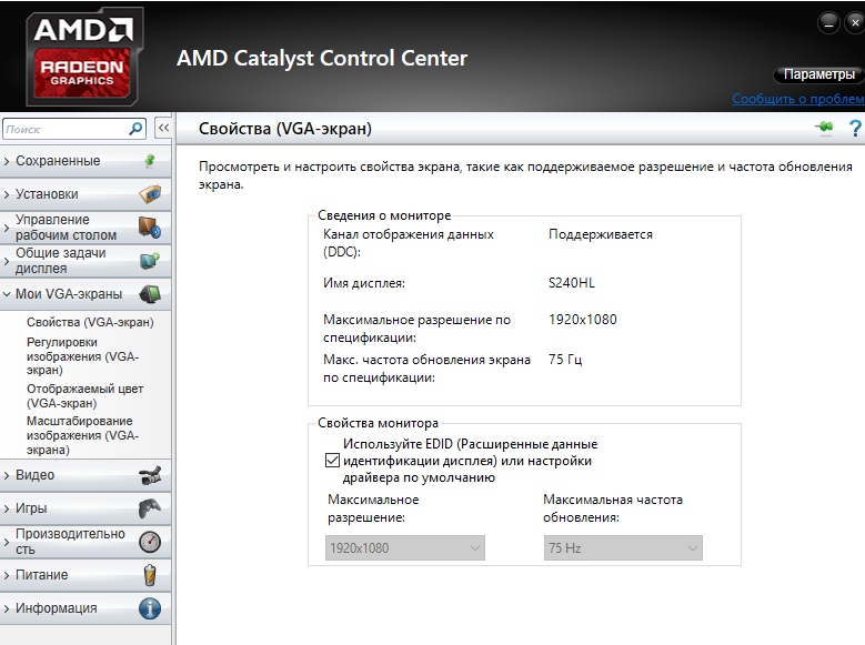 An increase in exhaust emissions is a common symptom of a failed catalytic converter. A damaged catalytic converter may also have symptoms confirmed by odor. Exhaust fumes emitted from the vehicle may have a different smell than before.
A sign of catalytic converter damage may also be excessive combustion of fuel or oil during vehicle operation. If our catalytic converter is not working properly, it may interfere with proper fuel consumption.
Catalyst Repair
If we notice the above symptoms of catalytic converter damage or if the indicator light is on, our catalytic converter should be repaired as soon as possible. A faulty catalytic converter or DPF filter can damage our car.
In the event that we suspect that the catalytic converter has failed, it is worth looking for a service that specializes in the repair of exhaust systems. Our company has been in the industry for almost 30 years, we have been dealing with exhaust system regeneration for several years. In the event of a catalyst failure, it is worth focusing on regeneration, the purpose of which is to restore the full performance of this element. Remanufacturing is an ecological, economic activity, definitely cheaper than buying a new part. In our offer, in addition to the remanufacturing service itself, we have many remanufactured components that we can send to any workshop for replacement or directly to the customer.
It is worth constantly monitoring the condition of our catalytic converter, its failure can be unexpected and very noticeable, as it will lead to immobilization of the car. Cars very often serve professional purposes, allow driving to work or are a working tool, all the more so in such cases they must be reliable. There are many symptoms indicating that the catalytic converter has been damaged — different sound, higher combustion, higher emissions exhaust or other color. Each of the signals that bother us can always be checked by a mechanic, this can allow us to avoid further breakdowns and higher costs.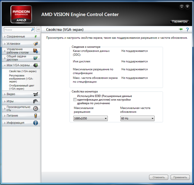
(Visited 1968 times, 4 visits today)
Similar to
.
Kaliński — Blog — Page 3 of 14
One of the most common catalytic converter failures in our vehicles is clogging. The accumulation of soot prevents the passage of exhaust gases, which can even clog the catalytic converter. What does a clogged catalytic converter look like if it can even immobilize a car? You will learn from our next text.
We have been in the exhaust business for almost 30 years and have a lot of experience when it comes to catalytic converters or particulate filters. In our blog, we have discussed the issue of catalysts many times, although we have never written in detail what a catalyst looks like inside .
Browsing through our blog, you will find articles such as: What is a catalytic converter made of? Where is the catalyst located? How to recognize a cut catalytic converter? Symptoms of a car catalyst failure? Without a catalyst and technical inspection?
This article will cover the inside of a catalytic converter, what it looks like and when it is clogged.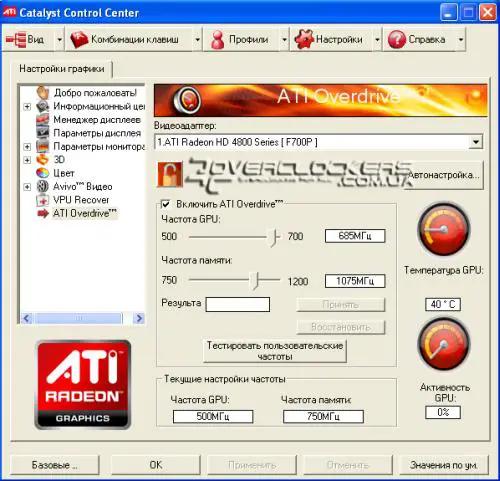
What does the catalytic converter look like inside?
Catalysts in the most simplified form consist of a body and a metal or ceramic insert, between which there is a cover. What does a catalyst look like, what shape does it have? The whole shape most often resembles a cylinder, and in heavy vehicles also a cube. If we cut the catalyst into two parts, we will see that the dominant element is its contribution. Inserts are made of metal or special ceramics. Regardless of the type of material from which the inserts are made, they have special channels impregnated with precious metals. The most important metals in the catalyst are palladium, rot and platinum. These elements play a very important role, they catalyze harmful substances, thereby reducing their emission into the atmosphere. Precious metals saturate channels in catalysts. What does a catalytic converter look like inside? This is a rather densely designed system in which the dominant element is the channels, whose role is to pass air through the system and catalyze it.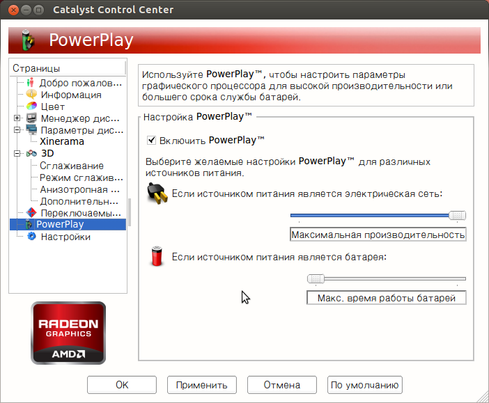
The catalytic converter is clogged in the cartridge due to improper operation or failure.
What does a clogged catalytic converter look like?
Catalysts, like all parts of the car, are destroyed during operation, sometimes they also become clogged or clogged. Catalysts become clogged, especially if they are not properly maintained. If we want to use them for as long as possible, they must self-repair. Regeneration is a process that allows you to restore the efficiency and functionality of the particulate filter or catalyst, self-regeneration is an identical process, but occurs spontaneously due to the correct operation of the element. In the case of catalytic converters, self-regeneration occurs when the operating temperature of the engine rises, and then the temperature of the catalytic converter rises. In this case, harmful substances are catalyzed. In particular, vehicles traveling in the city should run at an increased engine speed at least once a week, i.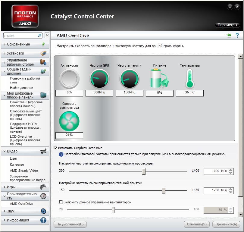 e. when driving at increased speeds on an expressway or highway. If there is no self-regeneration, the catalyst may become clogged or clogged.
Then a few questions need to be answered: what does a clogged catalytic converter look like? What does a clogged catalytic converter look like? What does a burnt catalytic converter look like? If our catalytic converter is regenerated very infrequently, soot and other contaminants can systematically accumulate inside it. Along with an increase in the amount of impurities in the channels of the catalyst, its permeability decreases, the passage of air is difficult. If too much soot accumulates, the entire catalytic converter may become clogged, which will lead to the immobility of the car. So what does a clogged or clogged catalytic converter look like? The appearance of a clogged catalyst is no different from a serviceable one, the difference is visible inside. In a clogged catalytic converter, due to soot and other impurities, the insert instead of white will be “dirty”, it will acquire gray-black colors. If you cut a clogged catalyst, you will see its section with black channels from soot. A clogged catalyst, if it is several or ten years old, may also have a scratched, dented or slightly rusted body.
In the topic of catalysts, it is also worth discussing the topic of their burnout, which can be understood in two ways. Some car owners, wanting to save money, try to regenerate catalysts in their own way, one of the “home regeneration” methods is “burning out”. The method consists in pouring a flammable liquid through a catalytic liner, such as a lighter grill, and then on fire. Answer yourself, what does a burnt catalyst look like? In the catalyst fired in this way, its ceramic insert melts, the insert is resistant to temperature, but not so high. The melting of the cartridge will make it necessary to replace it with a new one, which increases the cost of repairs, while the catalyst cannot be regenerated. Companies such as ours that regenerate DPFs and catalysts use various kinds of regeneration methods, one of them is firing in a special furnace. Our company uses a special Hartridge brand furnace, which is heated to a temperature of about 600 degrees, to roast the catalysts. Roasting loosens the contaminants and turns the soot to ash. After the firing procedure, we blow the catalyst with compressed air, clean its liner, this is our way of regenerating particulate filters, catalysts. A burnt and burned out catalyst looks like new, its interior is again fully functional and free.
Not so obvious
At first glance, there may not be a difference between a clogged or blocked catalytic converter. From the outside, both catalysts can be very similar to each other and there is no sign that one of them has failed. If, on the other hand, cut in half, we will notice the difference. An efficient catalyst will have a relatively clean insert, its channels will allow air and exhaust gases to pass through. What does a clogged catalytic converter look like? Its inside will be dirty, full of soot and sewage. Not everything is obvious and immediately visible. When it comes to diesel particulate filters and catalytic converters, you should trust professionals who diagnose the problem and then suggest the best solution. In case of problems with the exhaust system, please contact our company.
.
Exhaust gas temperature sensor (EGT) — signs of damage and repair
In modern internal combustion engines, exhaust gas temperature monitoring is necessary for proper control and diagnostics of the exhaust gas treatment system, as well as to protect individual components that are particularly sensitive to thermal overload. In addition, increasingly stringent regulations regarding exhaust emissions into the atmosphere mean that such a sensor is no longer an automotive overkill, but a necessary element of every modern car.
EGT for petrol and diesel engines
Exhaust gas temperature sensor (EGT), as the name suggests, is responsible for measuring the temperature of the exhaust gases.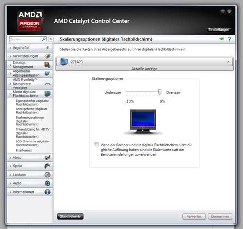 The received information is sent to the engine control unit or ECU in order to properly control the operation of the power unit and effectively reduce exhaust emissions into the atmosphere. The EGT sensor is most often located before the diesel oxidation catalyst (DOC) and/or before the diesel particulate filter (DPF). By accurately monitoring the exhaust gas temperature, the amount of injected fuel and the amount of particulate matter in the DPF can be accurately estimated, which makes the entire combustion process much more efficient and environmentally friendly. The consumption of fuel used in the DPF regeneration process is reduced, the catalyst temperature is fully controlled , and the exhaust gases emitted into the atmosphere are much cleaner. Exhaust gas temperature sensor EGT is currently used in both petrol and diesel vehicles.
Petrol units
In petrol engines, the EGT sensor primarily protects individual components from overheating. These are mainly the turbocharger and catalyst.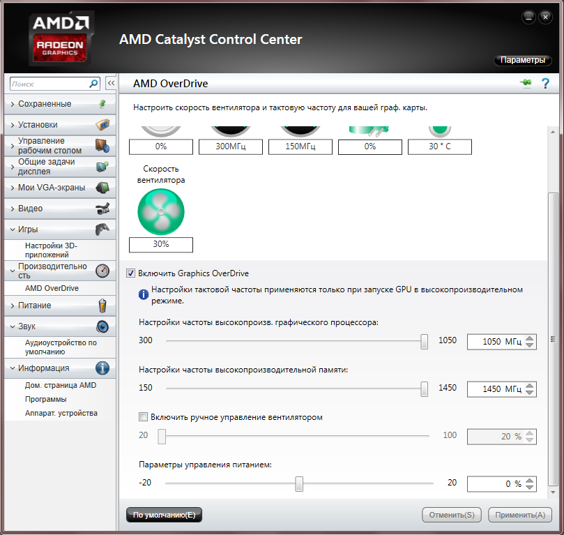 If the EGT sensor signals that the temperature of these components is too high, the engine control unit will take appropriate steps to reduce it, for example, by reducing the boost pressure or increasing the amount of fuel injected to cool the catalyst.
Diesel
In diesel engines, the EGT sensor also performs the function of a particulate filter temperature regulator, however, the main emphasis in such units is not only on protection against overheating, but also on ensuring that the temperature required for self-cleaning (regeneration) of the particulate filter particulate filter ( DPF) has been reached).
NTC and PTC
There are currently two types of exhaust gas temperature sensors. The first sensor detects the positive temperature coefficient (PTC) and the second one signals the negative temperature coefficient (NTC). The difference between the two elements is how the temperature is measured. The NTC sensor has high resistance at low temperatures and low resistance at high temperatures (NTC resistance decreases with increasing temperature). In turn, a PTC sensor based primarily on semiconductors (polycrystalline ceramics such as barium titanate) typically has a resistance that increases with temperature.
The flue gas temperature sensor fails due to… temperature!
Exhaust gas temperature sensor is not a reliable component. The most common cause of damage to this sensor, paradoxically, is too high a temperature, sometimes reaching over 900 degrees Celsius. In addition, excessive vibration can loosen the sensor’s internal connections, and any contamination will affect the response characteristics of the sensor, resulting in inaccurate temperature readings.0003
- extension of the DPF filter regeneration process associated with increased fuel consumption,
- unnecessary DPF filter regeneration,
- EGR system malfunction,
- exhaust gas temperature increase,
- failure of individual exhaust system components and critical components of the power unit.
Problems with the EGT sensor can cause the engine damage indicator to come on.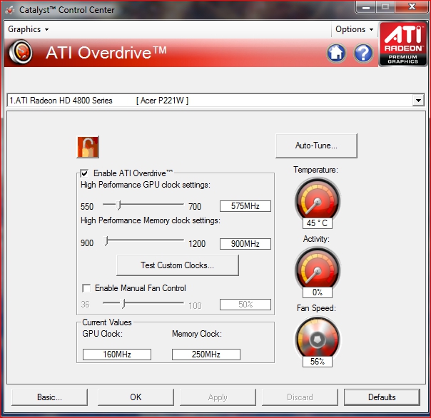 This fault code is stored in the powertrain ECU and can be checked with a diagnostic scanner. In a situation where it is found that the EGT sensor is damaged, it should be replaced with a new one as soon as possible, using only products from reputable manufacturers of this type of range.
Typical Flue Gas Temperature Sensor Fault Codes
P0544 : Exhaust Gas Temperature Sensor Bank 1 Sensor 1 Circuit Malfunction
P0546 : Exhaust Gas Temperature Sensor Bank 1 Sensor 1 — High Input
P2033 : Exhaust gas temperature bank 1 sensor 2 — signal high
P247A : Exhaust gas temperature sensor 1 bank 1 sensor 3 — out of range
P0549 : Exhaust gas temperature sensor bank 2 sensor 1 — signal high
P2031 : Exhaust gas temperature bank 1 sensor 2 — circuit malfunction , maybe even modern. I try to combine practice with theory, because I know that it is worth knowing not only how something works, but also what it should serve. However, in some respects I am an absolute traditionalist. Traditionally, I emphasize the importance of regular inspections and replacement of parts or fluids. And to clarify, the average driver can’t afford to skimp on any of these…
.
DPF Diesel particulate filter and catalytic converter
Both the catalytic converter and the diesel particulate filter play a very important role in the purification of exhaust gases. These elements are located close to each other in the exhaust system, which is why they are sometimes mistaken for one component. In fact, their structure and principles of operation differ. Catalysts, which have long been installed in all cars, in particular change the chemical composition of exhaust gases and reduce the content of harmful compounds. On the other hand, particulate filters are found only in cars with a diesel engine and are responsible for trapping particulate matter. Read the article and find out more about it!
Recovery and reaction
There are some similarities between a standard automotive catalytic converter and a diesel particulate filter — for example, both use a ceramic or metal component through which the exhaust gases pass. However, the main difference is that the diesel particulate filter is a design that collects soot and then burns it. On the other hand, the catalyst changes the chemical composition of the gas mixture while reducing the amount of pollutants released into the atmosphere. This reaction takes place on the surface of a ceramic block or monolith coated with a mixture of platinum, palladium or rhodium.
When do the catalytic converter and particulate filter fail?
Under normal operating conditions, the catalytic converter does not fill up or wear out and should theoretically last the lifetime of the vehicle. In fact, malfunctions do occur, for example, due to hot fuel residues entering the exhaust system from the combustion chamber. The ceramic cartridge can also be contaminated with oil from the exhaust manifold. The hard black coating that forms on the surface of the monolith prevents it from working and is very difficult to remove. Mechanical damage should also be taken into account. Stones thrown from under the wheels, if placed in the wrong place, can break the ceramic inlay. The metal core is more resistant to shock and temperature changes, but these types of catalysts are very expensive and not very popular on the market. The vast majority of modern catalytic converters are based on ceramics for economic reasons.
DPF specific failure modes
An important difference in operating range between a catalytic converter and a DPF is that over time the filter becomes filled with soot and other particulate matter. These particles burn out cyclically under certain engine operating conditions. During this process, a small amount of ash is generated each time, which eventually blocks the particulate filter and requires regeneration or replacement.
Clogged filter problems can vary greatly depending on the distance the vehicle is driven. At short distances, the engine temperature rarely reaches ideal operating conditions and then more soot is formed, which after a thermal reaction turns into ash. Therefore, sometimes it may be necessary to replace the DPF after a run of 20,000 km. kilometers, but more often in the region of 100 thousand. km. For some vehicles that only travel long distances, a diesel particulate filter can last up to several hundred kilometers, but these are truly unique situations.
When are the catalytic converter and particulate filter installed?
As a general rule, every vehicle manufactured after March 1, 2006 must have a catalytic converter. The situation is different for diesels. Diesel vehicles today are equipped with both a diesel particulate filter and a catalytic reactor to meet increasingly stringent emission standards. On the other hand, gasoline-powered vehicles, although they have integrated advanced catalytic converters, do not have a diesel particulate filter.
On some vehicles, the particulate filter and catalytic converter are separate and can be replaced separately. However, many modern emission reduction systems are integrated into one unit, and there is a tendency to move them closer to the exhaust manifold so that they can reach operating temperature faster. This protects the component from mechanical stress and cold, but in the event of a failure, its replacement is usually more expensive.
Similarities and differences
The differences between a catalytic converter and a diesel particulate filter are visible in design, operating principles and failure rates. The particulate filter usually requires periodic regeneration, and the catalytic converter can function normally during its entire service life. It is best to have service activities in a specialized car workshop, where the exhaust system will be thoroughly diagnosed.
Effective DPF regeneration method
It is worth noting that the difference between poor regeneration and service performed by a professional service affects the life of the particulate filter and its correct operation. Also, not all cleaning methods are equally effective. For example, service or induction firing removes soot, but does not remove ash, which eventually clogs the particulate filter.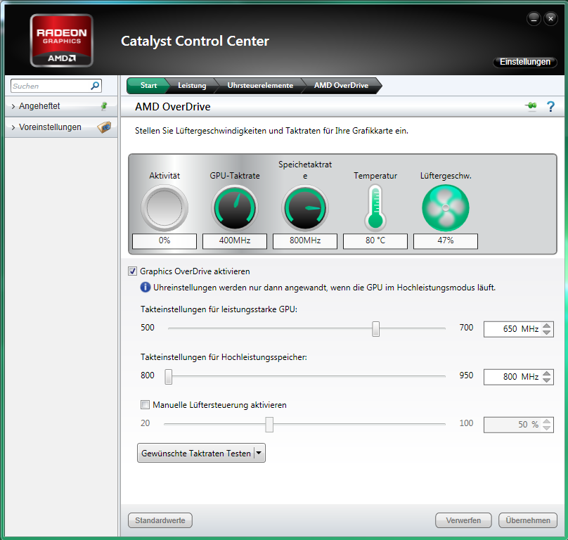 Therefore, at present, the best way to restore the filter to full performance is to clean the water in a specialized machine. A jet of liquid containing detergents thoroughly washes away dirt even from the smallest nooks and crannies. The DPF then goes through a drying process to get rid of the accumulated moisture. After the procedure, the filter is fully functional and practically does not differ from a new part, the purchase price of which is significant.
Take advantage of our services!
If you have problems with a clogged particulate filter, be sure to check out our offer! We deal with complex filter regeneration on a specialized machine. We also carry out diagnostics so that we can determine exactly what is causing the failure of the exhaust system. After cleaning, we carry out tests and then install the DPF in the car. You can come to us personally, send the particulate filter by courier or deliver it in any other convenient way. Do not overpay for new spare parts — choose a proven way of regeneration!
.
Medium temperature up to 1000°C
CCR1000 Catalyst Reactor Cell
The CCR1000 Catalytic Cell Reactor is a versatile stage designed to study catalytic reactions at high temperature and pressure. This allows the user to conduct small scale testing of catalyst formulations and evaluate results using a range of gas analysis techniques.
Samples are mounted on a practically non-reactive disposable ceramic fabric filter, which is placed inside the ceramic heating chamber. The carrier gas is introduced into the stage via a 1/16 high pressure gas line. The gas is then partially preheated and passed through the sample and a ceramic fabric filter. The heater tube is very narrow to prevent dead space and ensure that it remains hot enough to prevent condensation before it is available for gas analysis.
All parts of the cell in contact with the sample and gas are selected for their non-reactive properties; Most of the parts in contact with the sample and carrier gas are made of ceramic or stainless steel. This stage has optical access to the reaction chamber, making it ideal for use with reflected light microscopy and spectroscopic techniques, including Raman and FT-IR microscopy such as Operando.
Temperature precisely controlled by Linkam T9 controller6-S (using an S-type platinum/rhodium thermocouple) that can heat samples at rates up to an impressive 200°C/min. Thermocouple linearization (linearized to 0.1°C and displayed to 0.1°C) and cold junction compensation are performed internally in the T96-S controller.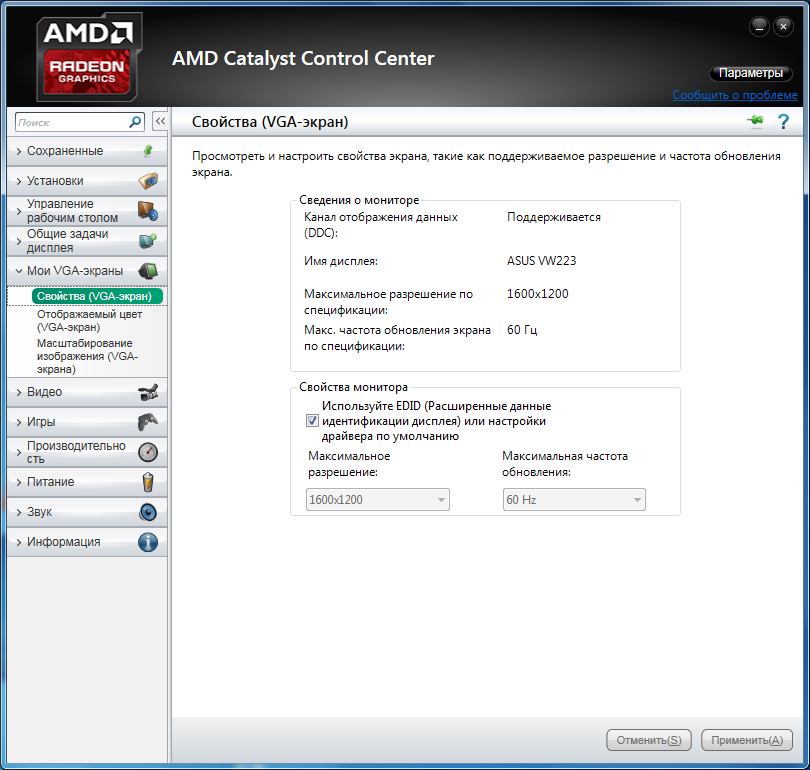
System requires CCR1000, ECP water circulation pump and T96-S controller, available with either LINK software for computer control or LinkPad touch screen for standalone control.
Temperature range. From ambient temperature to 1000°C.
Heating rate. 0.1°C to 200°C / min.
High degree of accuracy. The T96-S controller accurately controls temperature using an S-type platinum-rhodium thermocouple.
Various optical methods. Compatible with upright reflected light microscopes and other spectroscopic techniques including Raman and FT-IR microscopy such as Operando.
Water cooled. Water-cooled for safe operation above 300°C.
The CCR1000 is extremely versatile with many options and configurations and can be easily adapted to applications ranging from scientific research to commercial and industrial applications, including the following:
|
Catalysis The CCR1000 is used for high precision thermal analysis of catalytic reactions, from organic catalysts and metal ions to biocatalysts and photocatalyst materials. |
|
|
Semiconductors and electrical There is significant academic research and commercial interest in new materials for energy storage and electrocatalysis. The CCR1000 can be used to study their properties in combination with Raman spectroscopy and other microscopic and spectroscopic methods. |
|
|
Materials and metallurgy The critical components of the CCR1000 are made of stainless steel, which allows them to be used with some corrosive materials, including studies of the corrosion process of metal, alloys or galvanization. |
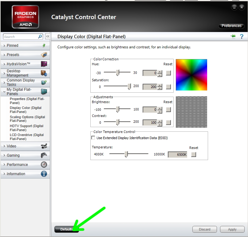
| Temperature range | Ambient to 1000 °C |
| Heating/cooling rate | 0.1°C to 200°C/min |
| Temperature stability | 0.1°C |
| Pressure | Up to 5 bar |
| Sample size | Chamber 5. 8 mm ø (holds 70-100 mg depending on sample type) 8 mm ø (holds 70-100 mg depending on sample type) |
| Working distance | 7.9 mm |
| Compatible | Reflected light, vertical and Raman microscopes. Mounting options are available for most microscopes*. |
Learn more
Take control of your experiment with the LINK software or the standalone LinkPad touchscreen with the T96 Temperature Controller.
Both the LINK software and the LinkPad have a single user interface that can monitor and control temperature and many other parameters including vacuum, humidity, tensile force and shear force (depending on the system). LinkPad provides an easy to use interface to T96 for full control without a PC. Profiles up to 100 ramps can be programmed, allowing complex processes to be simulated.
The LINK software enhances this with data logging and real-time graphical feedback. Optional modules to enhance your system include the LINK Imaging Module for synchronous image capture, the LINK Advanced Measurement Module for measuring key image characteristics, the LINK 21CFR11 module for data compliance, and LINK TASC for image-based thermal analysis.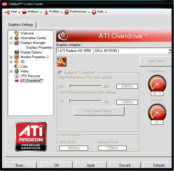
Imaging Station provides a digital imaging platform compatible with Linkam temperature and environmental control systems. Use our high resolution camera to capture images and videos of your samples while monitoring temperature and environmental conditions.
The imaging station has been specially designed with a swivel mechanism to give you more access to your Linkam stage, making it quick and easy to access the camera and change samples. It has a built-in LED light source for transmitted light with additional options for reflected light, polarization and phase contrast imaging.
The Imaging Station is also compatible with a range of long working distance lenses that can be easily switched using the quick release mechanism.
To purchase, ship, install, maintain or modify equipment for your laboratory, contact
This email address is being protected from spambots. You must have JavaScript enabled to view.
or call +7(495) 669-39-72
In focus:
Gas AR and KR LEXEL lasers (View, deep UV
Three-Schwadarupol GX-MS Agilent 7000c
Hi-End Cryogenic stations from Leiden Cryogenics B.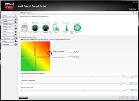 V.
V.
Tables for microscopy from Linkam Scientific Instr.0003
|
Contact information: Address: Perm, st. Academician Koroleva, 21. Technopark «Sosnovy Bor» Tel./Fax: 8 (342) 239-16-47; 8 (342) 239-17-65 E-mail: [email protected]; [email protected] Head of the Center: Doctor of Technical Sciences, Professor Ryabov Valery Germanovich |
The main activities of the center:
Study of the properties of cracking catalysts, their activity and selectivity. Determination of such characteristics of catalysts as: phase and elemental composition, attrition resistance, fineness, specific surface area and pore volume, elemental composition.
FCC Services:
- Evaluation of the activity of samples of industrial fluid cracking catalysts (FCC) for various types of feedstock;
- Studies of the kinetic parameters of the catalytic cracking process and the construction of its mathematical models;
- Analysis of hydrocarbon mixtures by gas chromatography;
- Determination of the fractional composition of petroleum products according to the ASTM D7213 method;
- Determination of specific surface and pore sizes of catalysts and sorbents;
- Elemental analysis of various materials;
- X-ray phase analysis of materials;
- Analysis on an electron microscope with an EMF attachment.
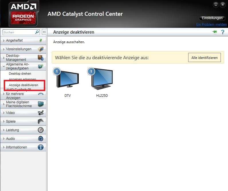
Center equipment:
1. MPSU Cyclic Propylene Steamer, manufactured by Grace (Germany)
2. Fluidized Bed Cracking Catalyst Testing Unit, manufactured by ACEy R+, Inc. Kaser Technology (USA)
3. HS-RGA catalytic cracking gas analysis system based on Agilent 789 gas chromatograph0, manufactured by AC Analytical Controls (Netherlands)
4. System for simulating the distillation of liquid petroleum products AC SIMDIS based on an Agilent 7890 gas chromatograph, manufactured by AC Analytical Controls (Netherlands)
5. System for detailed analysis of hydrocarbon composition of gasolines and gasoline fractions AC DHA according to the PIONA method based on an Agilent 7890A gas chromatograph, manufactured by AC Analytical Controls (Netherlands)
6. LECO CS-230HC Sulfur and Carbon Determination Unit, LECO (USA)
7. GEMINI VII 2390p Specific Surface Analyzer, Micromeritics (USA)
9. Bulk Density Apparatus, Grace (Germany)
10. Centrifuge for determining the specific pore volume of the catalyst when saturated with water Heraeus Multifuge X3 F, made by Thermo Scientific (USA) Germany)
12. Semi-automatic mill HP-M100P, manufactured by Herzog Maschinenfabrik (Germany)
13. X-ray diffractometer XRD-7000, manufactured by Shimadzu (Japan)
14. Inductively coupled plasma emission spectrometer i 6000, manufactured by Thermo Scientific (USA)
15. Atomic absorption spectrometer30 manufactured by iCE, manufactured by iCE Thermo Scientific (USA)
16. Microtrac S3500 Liquid Phase Laser Particle Sizer, Malvern Instruments (UK)
MPSU
manufactured by Grace (Germany)
The unit is designed to simulate the deactivation of a cracking catalyst in a fluidized bed under industrial conditions.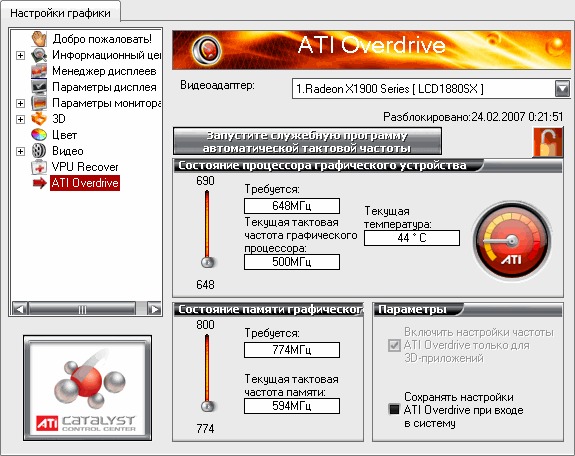
The method of cyclic propylene steaming consists in carrying out redox cycles at given temperatures (about 800 ° C) and time, simulating the operation of reactor-regenerator cycles in catalytic cracking units.
As a result of this deactivation of catalysts in laboratory conditions, samples are obtained that are identical in terms of active surface area and unit cell size to samples of commercial equilibrium catalytic cracking FCC catalysts. At the same time, the content of coke and sulfur compounds on the catalyst is similar to industrial samples.
____________________________________________________________________________________________
Fluidized Bed Cracking Catalyst Tester ACE R+
manufactured by Kayser Technology Inc. (USA)
The unit is designed to test the activity of fluidized bed cracking catalysts (FCC). It uses Kayser’s patented fluidized bed reactor. The ACE R+ plant is equipped with a unit for automatic introduction of the catalyst into the reactor and its withdrawal from the reactor.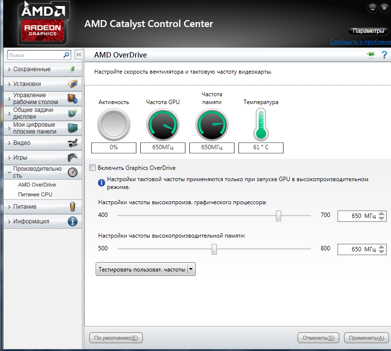 This allows for a complete multiple test of different catalysts without operator intervention after the start of the test process. The test is carried out in series of 6 samples of various weights. The installation is controlled via a computer with special software.
Both fresh catalysts and equilibrium catalysts (used in industry) can be tested. Catalyst loading volume from 5.25 to 11.25 g.
Feedstock loading (vacuum gas oil and similar products) can vary between 1.0-3.0 g/s (accurate to 0.002 g/s). Requirements for raw materials: Conradson index up to 10, density up to 1000 kg/m3, 60% of raw materials must have a boiling point above 538°C.
The ACE R+ reactor is made of 316L stainless steel. The design of the reactor allows the location of the feed injectors at different levels along the axis, which allows you to change the performance with the simulation of different contact times of the catalysts in the reactor.
Standard test temperature -514 °C for equilibrium.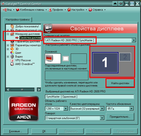 However, the process can be carried out at a temperature of 400–600 °C. The maximum operating temperature and overpressure in the reactor are 750°C and 0.65 bar, respectively.
The design of the installation allows simulating the operation of real industrial reactors with different contact times.
After the cracking reaction, the degree of coking of the catalyst (directly inside the unit) and its other characteristics are determined. The resulting liquid and gaseous cracking products are analyzed by gas chromatography, which makes it possible to determine the degree of conversion and the selectivity of the catalyst.
The unit can be used for the simultaneous solution of the following tasks:
1. Determination of the degree of conversion and selectivity of cracking catalysts, gas and coke factors;
2. Evaluation of suitability for processing various types of raw materials;
3. Studies of the kinetic parameters of the process and the construction of mathematical models;
4.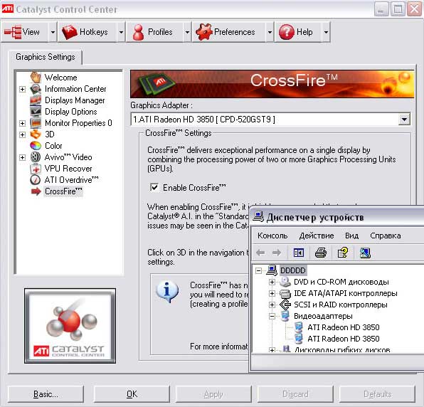 Analysis of the efficiency of removing hydrocarbons from the catalyst before the regeneration stage.
____________________________________________________________________________________________
HS-RGA catalytic cracking gas analysis system based on Agilent 7890
gas chromatograph
manufactured by AC Analytical Controls (Netherlands)
The HS-RGA (High Speed Refinery Gas Analysis) system allows you to analyze gaseous products of the catalytic cracking process with the determination of hydrogen and hydrocarbon gases from methane to C6 inclusive. The chromatograph has 2 lines — for the analysis of hydrogen on a thermal conductivity detector and for the determination of hydrocarbon gases on a flame ionization detector. Helium is used as a carrier gas in the hydrocarbon line, and nitrogen is used for hydrogen analysis. The analysis is carried out automatically, directly at the end of the test of each portion of the catalyst. Based on the results of the analyzes, the gas factor of the catalyst is determined.
____________________________________________________________________________________________
System for simulating the distillation of liquid petroleum products AC SIMDIS based on an Agilent 7890A gas chromatograph
manufactured by AC Analytical Controls (Netherlands)
The system allows simulating the determination of the fractional composition (Simulated Distillation) of medium fractions of oil and oil products in accordance with ASTM D7213. The obtained results of the analysis are comparable to the fractional composition measured according to ASTM D86 and ASTM D1160.
The analyzed objects are oil products with boiling ranges from 100 °C to 615 °C under normal conditions (kerosenes, diesel fractions, atmospheric gas oils, products of secondary oil refining processes, etc.).
Flame ionization detector, carrier gas — helium. The system uses special capillary columns for simulated distillation 5 m long, the maximum thermostating temperature of the columns is up to 425 °C.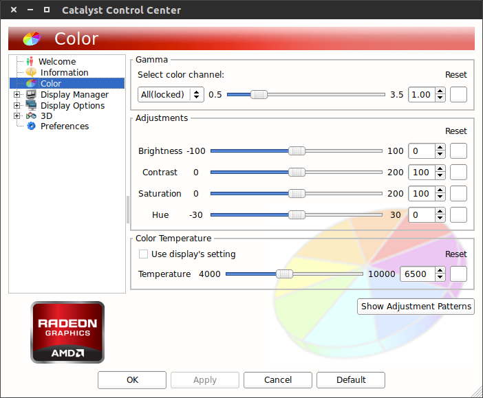
____________________________________________________________________________________________
System for detailed analysis of the hydrocarbon composition of gasolines and gasoline fractions AC DHA according to the PIONA method based on an Agilent 7890A gas chromatograph
manufactured by AC Analytical Controls (Netherlands)
PIONA analysis (Paraffins, Isoparaffins, Olefins, Naphthenes, Arenes) is the determination of the group composition of gasoline fractions in accordance with ASTM D6729.
The system is designed for the quantitative analysis of individual hydrocarbons up to C9indicating their physical characteristics and boiling points. In addition to hydrocarbons, it is possible to determine oxygen-containing compounds (ethanol, MTBE, etc.). Based on the results of the analysis, specialized software calculates the octane number (OM) of the fraction under study.
The system uses special capillary columns for effective separation of hydrocarbons 100 m long Flame ionization detector, carrier gas — helium.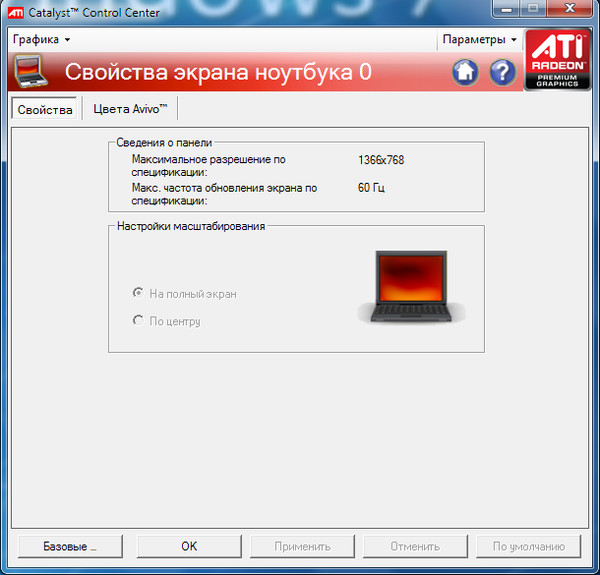 The operating temperature of the column thermostat is up to 270 ?.
Gasolines and gasoline fractions with a boiling point of no more than 195 °C under normal conditions can serve as analyzed objects.
____________________________________________________________________________________________
LECO CS-230H Sulfur and Carbon Determination Unit
manufactured by LECO (USA)
The unit is designed to determine the content of carbon and sulfur in a sample by burning it in a stream of oxygen at high temperature in a special induction furnace using combustion accelerators (metal chips, in particular tungsten). Combustion is accompanied by the conversion of all carbon and sulfur compounds into their oxides, the amount of which is then analyzed using an infrared detector in the exhaust gas stream.
The accuracy of the analysis for the content of sulfur and carbon at a nominal sample weight of 1 g is 0.0002 wt.% (2 ppm). The range of determined concentrations in this case is from 0.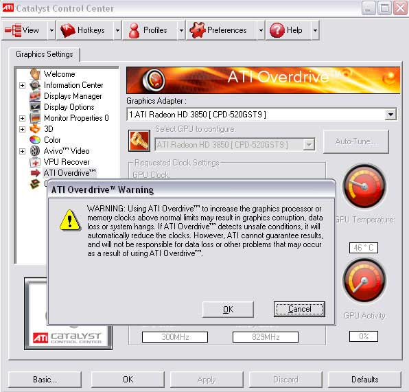 0004 to 0.4 wt.% (4-4000 ppm) sulfur and from 0.0004 to 3.5 wt.% carbon. At the same time, this range can be significantly expanded by increasing or decreasing the mass of the sample to almost 100% carbon or sulfur content at the expense of some decrease in accuracy.
The unit can be used to analyze catalysts, ceramics, glass, carbon steels and cast irons, copper and aluminum alloys, refractory metals, ore materials and other similar samples.
____________________________________________________________________________________________
GEMINI VII 2390p Surface Analyzer
manufactured by Micromeritics (USA)
The analyzer is designed to analyze the specific surface area and pore size of various porous materials by measuring the nitrogen adsorption isotherm and applying one of the calculation methods (in particular, the BET theory, Langmuir, etc.). In addition, the analyzer is able to determine the area and volume of micropores (for example, in zeolites) and the distribution of pore sizes along the adsorption isotherm. There is also an attachment for degassing the analyzed sample at temperatures up to 400°C in a helium stream.
The interval of measured values for the specific surface ranges from 0.01 m2/g and above (up to several thousand m2/g), and for the total pore volume — from 4 × 10⁻⁶ m3/g and above.
The instrument can be used to analyze catalysts, sorbents, activated carbons, zeolites, ceramics, glass, mineral materials and many other similar samples.
____________________________________________________________________________________________
Equipment for determining the resistance to attrition of microspherical catalysts DI
manufactured by Grace (Germany)
The unit is designed to determine the so-called Davison Index (the ratio of catalyst fractions with a particle size of less than 20 microns before and after analysis), which characterizes the attrition resistance of microspherical fluid catalytic cracking (FCC) catalysts.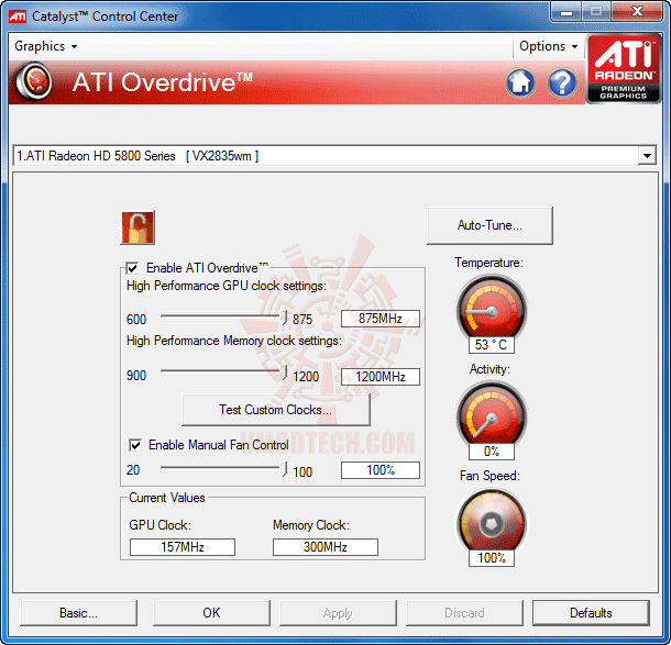 Direct abrasion takes place in a special cyclone vessel with tangential air supply connected to the bottom of the cyclone.
Bulk Density Apparatus
manufactured by Grace (Germany)
Designed to determine the set bulk density — this is the density of the catalyst sample layer in the cylinder in an unpacked form. It is determined by filling the cylinder of the device (volume 25 ml) with a catalyst and removing the excess using a special ring, after which the cylinder is weighed.
____________________________________________________________________________________________
Heraeus Multifuge X3 F
manufactured by Thermo Scientific (USA)
Centrifuge with special closed rotor for 6 samples. The maximum rotation speed is 15200 rpm. The centrifugation temperature range is from minus 10 to 40?C.
It is used to analyze the specific pore volume of a catalyst when saturated with water: a sample of the catalyst is impregnated with deionized water, after which the excess water is separated using a centrifuge.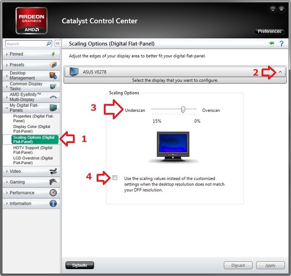 From the amount of water remaining in the sample (determined by mass), the total pore volume of the water is calculated.
____________________________________________________________________________________________
Unit for determination of CO oxidation activity of fluidized-bed cracking catalysts
manufactured by Grace (Germany)
The unit is designed to measure the activity of the catalyst in the oxidation of CO to CO2 (the so-called CO-index). This parameter is extremely important for the catalyst regeneration stage, since if the activity in CO oxidation is insufficient, then an open flame may occur in the regenerator due to the formation of a combustible mixture of CO and air. This can result in equipment damage and deterioration of the catalyst.
The analysis method includes passing a mixture of CO and synthetic air through a fluidized catalyst bed in a quartz reactor at a temperature of 615°C and analyzing the exhaust gases with an infrared detector for CO2 content.
____________________________________________________________________________________________
HP-M100P semi-automatic mill
manufactured by Herzog Maschinenfabrik (Germany)
Designed for grinding catalyst samples for further X-ray phase analysis on an X-ray diffractometer.
Can grind hard materials with a grain size of less than 10 mm and up to a Mohs hardness of 9.
____________________________________________________________________________________________
X-ray diffractometer XRD-7000
manufactured by Shimadzu (Japan)
Installation for qualitative and quantitative analysis of the phase composition of catalysts, ores, waste, crystalline intermediates and products, anti-corrosion coatings, etc. The use of this device allows you to determine the type of minerals, their crystal structure.
____________________________________________________________________________________________
Inductively Coupled Plasma Emission Spectrometer iCAP 6000
manufactured by Thermo Scientific (USA)
Spectrometer in combination with a special Mars microwave sample preparation system (CEM, USA), acid subboiling distillation units (Distillacid BSB-939-IR, Germany) and deionization water purification (Synergy millipore, France) ) allows for high-precision quantitative analysis of the content of metals and non-metals (from Li to U) in water, aqueous solutions and solid samples (alloys, catalysts, high-purity substances, etc.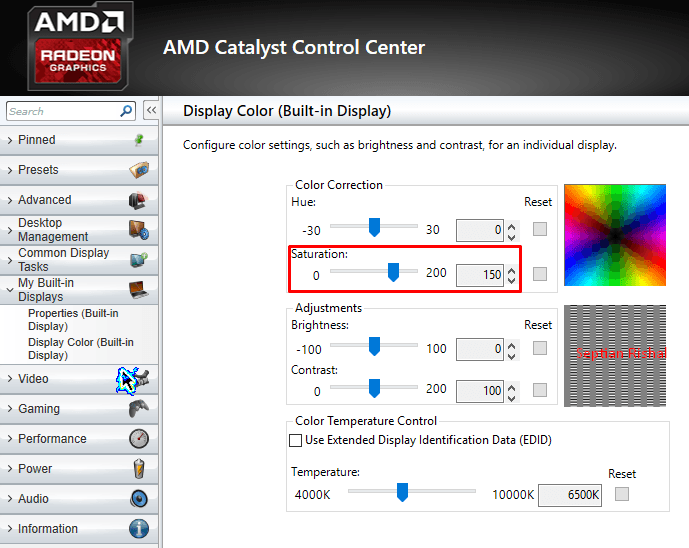 ).
).
The design of the spectrometer provides simultaneous measurement of analytical lines in the range from 166 to 867 nm. Optical resolution — less than 0.007 nm. The spectrometer is equipped with a new generation CID86 semiconductor detector and a powerful, highly stable solid-state RF generator (27.12 MHz). The generator maintains a stable plasma when analyzing samples of various compositions. The power supplied to the plasma is 750-1350 watts. The device is equipped with systems for working with high-salt solutions and hydrofluoric acid.
iCE 3000 Atomic Absorption Spectrometer
manufactured by Thermo Scientific (USA)
The spectrometer allows quantitative analysis of metal content in aqueous solutions in the modes of flame and electrothermal sample atomization.
The spectrometer is equipped with flame and electrothermal atomizers. Echelle optical scheme. Spectral range 185-900 nm. Radiation source — automatic self-aligning turret for 6 lamps with a hollow cathode. Silicon coating of optical elements. Corrosion resistant high performance atomizer. Digital control of gas flows. Three-level temperature control of the graphite cuvette. The high modulation frequency (200 Hz) provides reliable recording of a rapidly changing signal. Highly effective background correction QuadLine, Zeeman (0.8 T, 100 Hz) and combined. Universal burner and spray chamber for all elements to be determined, matrices to be analyzed and types of gas mixtures. GFTV real-time monitoring of the processes inside the graphite cuvette, sample injection, drying, ashing.
____________________________________________________________________________________________
Microtrac S3500 Liquid Phase Laser Sizer
manufactured by Malvern Instruments (Great Britain)
The analyzer is designed to determine particle sizes in the liquid phase in the range of 0.021-2816 µm. Analysis time 10-30 s. The analyzer includes a recirculator module with an SDC ultrasonic disperser.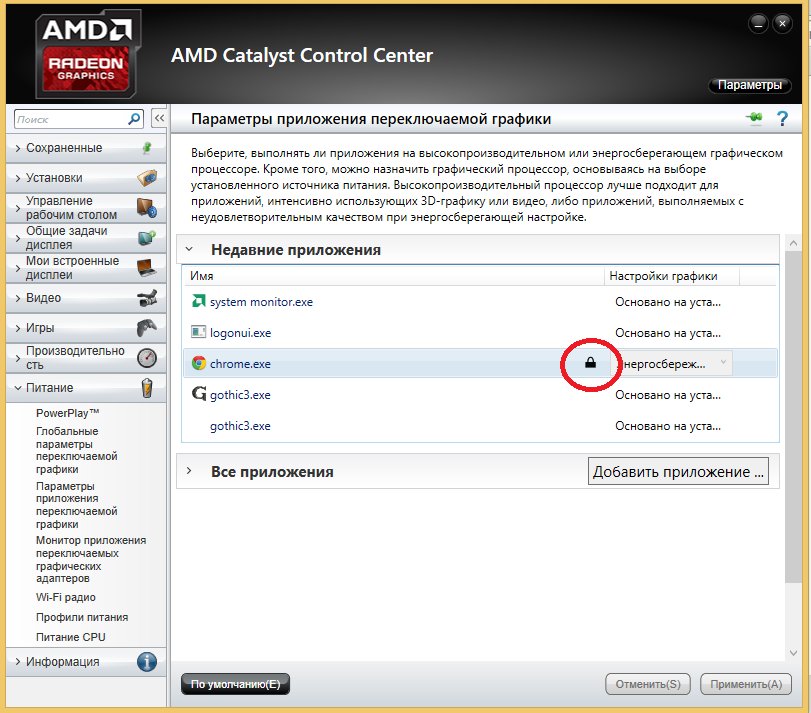 The analyzer is fully automatic and controlled by specialized software.
Control of chemical catalysts with sculpture light
Scientists strive to make chemical reactions more
efficient, optimizing the action of catalysts, writes
eurekalert.org co
Link to Science.
The role of catalysts for a chemical reaction is to
speed up the process and get out of it whole. At the same time, as a rule,
not all parts of the catalyst are involved in the process. But what if
it was possible to force the unused parts of the catalyst
participate? Chemical reactions can happen faster
or more efficient.
Materials scientists at Stanford University led by Jennifer
Dionne did just that, using easy and advanced methods.
manufacturing and characteristics to endow catalysts with new
opportunities.
In a proof-of-concept experiment with catalysts
served as palladium rods, the width of which was approximately
1/200 of the width of a human hair.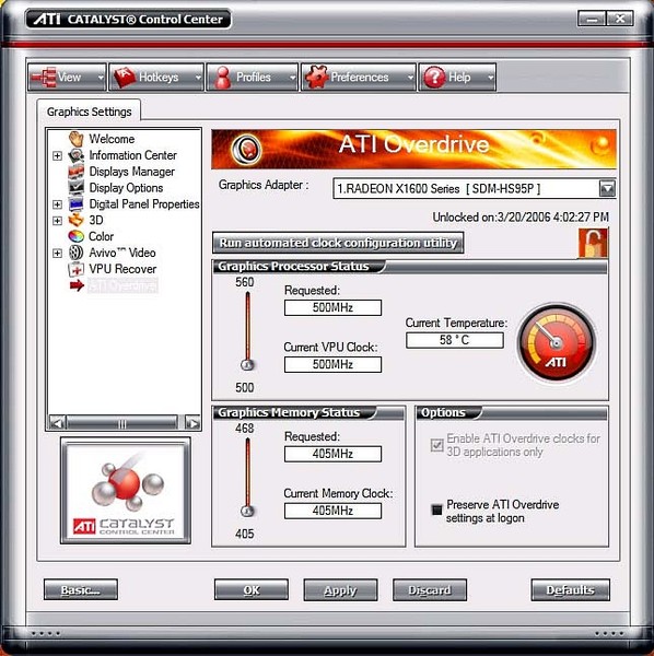 The researchers placed these
nanorods over gold nanorods that
focused and «shaped» the light around the catalyst. This
sculpted light changed the areas on the nanorods where
chemical reactions took place with the release of hydrogen. This work
may be the first step towards more efficient catalysts, new
forms of catalytic transformations and, possibly, even
catalysts capable of supporting more than one reaction
simultaneously.
“This study is an important step in the implementation
catalysts optimized from atomic to reactor —
said Dionne, assistant professor of materials science and engineering,
lead author of the article. — The goal is to understand how to
by appropriate shape and composition we can maximize
reactive area of the catalyst and control which reactions
are happening.»
To simply observe this reaction, it was required
exceptional microscope capable of imaging active
chemical process on an extremely small scale.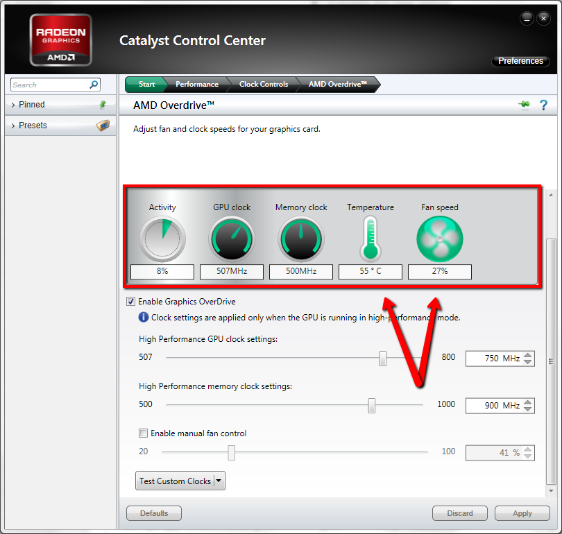 «Difficult
observe how catalysts change under reaction conditions, because
that nanoparticles are extremely small, said Catherine Sitwu, a former
PhD student in Dionne’s lab and lead author of the paper. —
The characteristics of a catalyst on an atomic scale usually determine whether
where the transformation takes place, so it is very important to distinguish that
takes place inside a small nanoparticle.”
For this particular reaction — and later experiments on
catalyst control — the microscope also had to be
compatible with the introduction of gas and light into the sample.
To achieve this, the researchers used
transmission electron microscope for environment in
Stanford Nano-Joint Center with a special nozzle,
previously developed by the Dionne lab, for light penetration.
As the name suggests, transmission electron microscopes
use electrons to image samples, which provides
higher magnification level than classic optical
microscope, and the environmental features of this microscope mean
that gas can be added to what is otherwise
airless environment.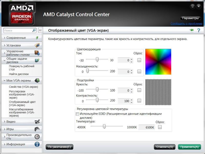
“Essentially, you have a mini-laboratory where you can conduct
experiments and visualize what is happening on an almost atomic
level,” Sitwu said.
Under certain conditions of temperature and pressure, palladium,
rich in hydrogen releases its hydrogen atoms. To
see how light will affect this standard catalytic
transformation, the researchers set up a gold nanoscale
rod developed using equipment at
Stanford Nanotechnology Joint Venture and
nanotechnology factory at Stanford to
located under the palladium and acted as an antenna, collecting
incoming streams of light and directing them to the nearest catalyst.
“First, we needed to understand how these materials
transform naturally. Then we started thinking about
how we could modify and actually control,
how these nanoparticles change,” Sitwu said.
Without light, the most reactive dehydrogenation points are
two vertices of the nanorod. The reaction then goes through
nanorod, releasing hydrogen along the way. However, with light
researchers were able to manipulate this reaction so that it
spread from the middle outward or from one tip to
to another. Based on the location of the gold nanorod and
lighting conditions, the researchers managed to create many
alternative hotspots.
This work is one of the rare examples showing that it is possible
customize the behavior of catalysts even after they have been manufactured. it
offers significant potential for efficiency gains in
one catalyst level. One catalyst can play a role
many, using light to perform several of the same
reactions on its surface or potentially increasing
the number of sites for reactions. Light control can also
help scientists avoid unwanted side effects that
sometimes occur.
[Photo: eurekalert.org]
Kinetic regularities of isoprene polymerization under the influence of a catalytic system based on neodymium bis-(2-ethylhexyl)phosphate
Recently, studies aimed at expanding the range of rare-earth catalytic systems for the polymerization of dienes have been actively continued. There has been renewed interest in catalysts based on neodymium bis-(2-ethylhexyl)phosphate (EHPP) in connection with their sale in large-scale industrial production of stereoregular rubbers. There is no description of the kinetics of isoprene polymerization in the presence of these catalysts in the literature. At the same time, kinetic studies are necessary for detailed process control and improvement of the quality of commercial rubber.
In addition to the neodymium compound, the composition of the catalyst under study includes triisobutylaluminum (TIBA, AlR’ 3 ), a chlorine-containing organoaluminum compound, for example, diisobutylaluminum chloride (DIBACH, AlR” 2 Cl) and a diene hydrocarbon (butadiene, isoprene, piperylene). Optimally, the catalyst is homogeneous [1].
Polymerization of isoprene with a catalytic system based on EHFN proceeds without an induction period, which indicates a high rate of the formation of active sites (initiation reactions). The nature of the kinetic curves describing the process of formation of polyisoprene at different temperatures in the range from 0 º to 50 º practically does not change (Table 1).
Table 1
Kinetic parameters of polymerization of isoprene (IS) as a function of polymerization temperature
T floor , o C
Polymerization rate, Vp∙10 2 , mol/l∙min
Number of active centers, n a %
0
0.6
7
20
1. 5
8
50
4.1
9
70
3.4
11
Under these conditions, the rate of polymerization increases with increasing temperature, while the number of active centers remains unchanged and averages 10%.
At 70 º, a slight decrease in the polymerization rate is observed, which may be due to the thermal instability of some types of active centers at high temperature (Fig. 1).
Fig. 1. Kinetics of polymerization of isoprene (IS) depending on temperature a , calculated from the slope of the straight line, is 21 ± 2 kJ/mol, which practically does not differ from the value of E a previously established in our laboratory for similar processes using a catalyst based on an alcohol solvate of neodymium chloride, equal to 20 ± 2 kJ/mol. These activation energies are typical for polymerization reactions with Ziegler-Natta catalysts.
Fig. 2. Arrhenius dependence for the polymerization of isoprene
Polymerization conditions: [ I — c 5 H 8 ] = 1.0 MOLS/L, [ ] [ [ 91AM 10 -4 mol/l, solvent — hexane.
From the logarithmic dependence of the polymerization rate on the initial monomer concentration (Fig. 3), the first order of the reaction for the phosphate catalytic system with respect to the monomer was determined, which coincides with the first order of the analogous dependence for the catalyst based on an alcohol solvate of neodymium chloride.
Fig. Fig. 3. Dependence of the initial rate of isoprene polymerization on monomer concentration
Polymerization conditions: [Nd]=1.5∙10-4 mol/l, pol=50 º, solvent – hexane.
It is known that the rate of polymerization of isoprene on a chloride catalyst is proportional to the catalyst concentration to the first power.
The dependence of the reaction rate on the phosphate catalyst concentration is more complicated and is determined by the process temperature (Fig. 4, Table 2).
Tpol, º
0
20
50
70
Catalyst reaction order
NdA 3 *– TIBA – DIBAH – pp**
1. 1
1.3
1.5
2.0
* – acid residue of bis-(2-ethylhexyl)phosphoric acid, **pp – piperylene.
C 2 N 5
|
|| O — SN 2 — SN — SN — 2 — SN 2 — SN 2 — SN 3
-O
O — SN 2 — SN 2
— 2 2 — CH 2 — CH 2 — CH 3
S 2 H 5
In order to make sure that the fractional procedure for the reaction of the catalyst is determined by the use of 2-Eilhexilphosphates of the Rare Elements (RZE) in its composition, a polymerization of a catalyst based on 2-EGF of the gadolinium was carried out at 50 º. The order of reaction with respect to the catalyst in this case is 1. 5 and coincides with the order calculated for polymerization using a catalyst based on neodymium 2-EHF under similar conditions (Fig. 5).
Fig. Fig. 5. Dependence of the initial rate of isoprene polymerization on the concentration of
catalyst based on gadolinium
Polymerization conditions: Tpol=50 0 C, [ID]=1.5 mol/l, hexane.
Catalyst composition: GdA 3 — TIBA — DIBAH — p.
It is known from the literature that 2-ethylhexylphosphoric acid used for the synthesis of neodymium salt is a dimer. The study of the structure of neodymium 2-ethylhexylphosphates in a number of studies made it possible to establish that the neodymium compound has a dimeric bridge structure, which is formed with the participation of an electron donor, oxygen of acid residues [2]. The oligomeric structure of REE dialkyl phosphates is also evidenced by the data published in [3].
The results of the calculation of the reaction order for the catalyst are in accordance with the existing ideas about the structure of active sites, which are a set of monomeric, dimeric and, possibly, larger complexes of neodymium compounds with an organoaluminum compound. If we depict only the neodymium part of the active center, not burdened with numerous aluminum derivatives, we can imagine two types of active centers in a simplified way — the monomeric form of the neodymium compound and the dimeric one (Fig. 6).
Fig. 6. Structure of the neodymium part of the active center of the catalyst
R — 2-ethylhexyl, R ‘ — isobutyl.
Polymerization involving monomeric and dimeric centers is probably characterized by different activation energies. It can be assumed that, at a low polymerization temperature, it is mainly centers based on the monomeric form that are active in the process. As a result, we observe the first order of the reaction with respect to the catalyst. As the temperature rises, the dimeric structures also become active. This is manifested in an increase in the order of the reaction with respect to the neodymium concentration up to 1.5–2.0.
As already noted, knowledge of the kinetic dependences makes it possible to control the properties of the polymer. Variation of the monomer concentration in solution is one of the levers for regulating the molecular weights of the synthesized polyisoprene.
As can be seen from Table 3, with an increase in the concentration of the monomer in solution, the molecular weights of the studied “phosphate” polyisoprenes increase, while the width of the molecular weight distribution remains unchanged. An increase in the polymerization temperature leads to a decrease in molecular weights.
Table 3
Comparative characteristics of catalysts based on neodymium chloride alcohol solvate
and neodymium 2-ethylhexylphosphate in the polymerization of isoprene
|
Catalyst |
T floor , o C |
[i-C 5 H 8 ], wt % |
Polymer yield, % |
Molecular weight of polyisoprene |
Content 3. |
||
|
Mn 10 -3 |
Mw 10 -3 |
Mw Mn |
|||||
|
NdA 3 — TIBA — DIBAH — pp |
25 |
10 |
93.3 |
585 |
1786 |
3. |
1.9 |
|
20 |
92.4 |
654 |
1984 |
3.0 |
2.6 |
||
|
50 |
10 |
95.5 |
388 |
1211 |
3. |
3.2 |
|
|
20 |
89.9 |
413 |
1310 |
3.2 |
2.9 |
||
|
NdCl 3 IPS* — TIBA — pp |
25 |
10 |
94.15 |
418 |
1483 |
3. |
2.1 |
|
20 |
93.86 |
477 |
1620 |
3.4 |
2.0 |
||
|
50 |
10 |
95.8 |
335 |
1263 |
2. |
3.0 |
|
|
20 |
89.6 |
400 |
1420 |
3.6 |
2.5 |
||
*IPA — isopropyl alcohol.
Polymerization conditions: [ Nd] = 1.5∙10 -4 mol/l, time — 60 min, solvent — hexane.
It should be noted that the investigated «phosphate» polyisoprene has a higher molecular weight than the «chloride». Comparable polyisoprenes do not differ in microstructure. The content of 3,4-units increases with increasing temperature, but does not exceed 3. 2%.
Fig. 7. Effect of temperature on the dependence of the number average molecular weight
from the concentration of the catalyst
Polymerization conditions: [ I — c 5 H 5 912 29/1,AN , the solvent is hexane.
Fig. 8. Effect of temperature on the dependence of the weight average molecular weight of
on the concentration of catalyst
Polymerization conditions: polymerization time 30 min. [
With a decrease in catalyst concentration, the molecular weights of piliisoprene increase in the polymerization temperature range from 0 º to 50 º. At 70 º, a decrease in the catalyst concentration has practically no effect on the change in molecular weights. The polymerization temperature significantly affects the level of number average and weight average molecular weights. An increase in the polymerization temperature from 0 º to 70 º leads to a decrease in the molecular weights of the studied polymers (Fig. 7, 8). A change in the process temperature in the studied interval has little effect on the value of the polydispersity coefficient of polyisoprene (Fig. 9).
Polyisoprene has a fairly wide molecular weight distribution, the value of the polydispersity coefficient is in the range of 3–4. This is characteristic of most polydienes synthesized with REE-based catalysts and is determined by the presence of several types of active centers in such catalytic systems.
The content of 3,4 units increases with increasing temperature from 1 at 0 º to 3.3 at 70 º (Fig. 10).
|
01725 8 ]=1. 0 mol/l, time — 30 minutes, solvent — hexane.
Synthesized polymers have a narrower molecular weight distribution and the same microstructure compared to industrial SKI-5.
Tested polyisoprene samples have higher ductility and slightly lower elastic recovery than factory samples, at equal Mooney viscosities. And rubber compounds based on polyisoprene obtained using a bis-2-ethylhexyl phosphate catalyst are characterized by the same content of carbon-rubber gel with a slightly higher swelling index compared to rubber compounds based on SKI-5. All this should lead to a better processability of rubber and to an improvement in its technological properties.
Rubber compounds based on the studied polymer vulcanize faster and are characterized by a higher torque value M H compared to compounds based on SKI-5 and, consequently, higher tear and tear strength characteristics (Table 4).
Thus, the studied system based on neodymium 2-alkyl phosphate is an effective catalyst for the polymerization of isoprene and makes it possible to obtain polyisoprene with desired molecular weight characteristics and with a content of cis units of at least 97%. The synthesized product is not inferior in physical and mechanical properties to industrial synthetic rubber SKI-5.
References:
1. Bubnova S.V., Bodrova V.S., Dyachkova E.S., Drozdov B.T., Vasiliev V.A. Polymerization of isoprene with catalysts based on neodymium 2-ethylhexyl phosphate // Kauchuk and Rezina, 2014. — No. 1. — P. 16–19.
2. M.P. Jenson, R. Chiarizia, V. Urban, Investigation of the aggregation of the neodymium complexes of dialkylphosphoric, -oxothiophosphinic, and -dithiophosphinic acids in toluene // Solvent Extraction and Ion Exchange. — 2001. — No. 19(5). — R. 865-884.
3. Yatsimirsky K.B., Kostromina N.A., Sheka Z.A., Davidenko N.K., Kriss E.E., Ermolenko V.I. Chemistry of complex compounds of rare earth elements. – Kyiv: Naukova Dumka, 1966.
The authors thank the leading researcher I.M. Tsypkin for help in carrying out physical and mechanical tests of rubbers, as well as to M.A. Eremin for help in studying the molecular weight characteristics of polyisoprene.
Rosneft launched Russia’s first experimental complex for the production of catalysts — Kommersant Samara
Rosneft is actively involved in solving one of the important tasks of the innovative development of oil refining — reducing dependence on the supply of imported catalysts. At its sites, the company develops and manufactures products and services for catalytic processes, which, in turn, are the basis of the efficiency of oil refining. An important role in this work is played by the Novokuibyshev Catalyst Plant, whose activities help maintain the technological stability of the Russian oil refining industry, as well as save millions of dollars in the purchase of imported raw materials.
Heading for import substitution
For a long time, the uninterrupted operation of some catalytic processes depended almost entirely on the supply of imported catalysts. Therefore, Rosneft pays close attention to the development and development of the production of domestic catalysts, including its own production.
Currently, two catalyst enterprises operate within the perimeter of the largest oil and gas company in Russia — the Angarsk and Novokuibyshevsk plants. In addition, on the basis of the Sterlitamak Catalyst Plant, a joint venture LLC RN-Kat was created, which produces catalysts for hydrotreating and hydrocracking. At the same time, work related to catalysis and catalysts is being carried out at the sites of three corporate research institutes.
Novokuibyshevsk helps
Until recently, there was no modern technology in Russia for the regeneration of hydroprocessing catalysts on an industrial scale. Novokuibyshevsk Catalyst Plant (NZK LLC) is helping to solve this problem today.
Regeneration is carried out on a special unit, put into operation at the end of 2016, which is one of the most modern and technically equipped in Europe. Catalysts are processed according to the “out of the reactor” technology, which is a generally accepted world practice in oil refining. With its help, the main physical and chemical properties and activity of catalysts are restored as carefully and skillfully as possible to the maximum possible values for further operation at the refinery. “Regeneration takes place on average at a temperature of 450 C. The procedure is carried out every 1–3 years under careful laboratory control, which is very important for maintaining the structure of the catalyst. After the procedure is completed, the catalyst is returned to the refinery, loaded and operated at the enterprises. Catalysts come to us from all Rosneft plants, as well as from Gazpromneft, TAIF and other companies. Regeneration is one of the ways to help enterprises save their funds and technological resources, while fulfilling all production plans,” says Alexei Golubev, General Director of Novokuibyshevsk Catalyst Plant.
Since the launch, the unit has managed to process almost 3.5 thousand tons of catalysts from the largest oil refineries of Rosneft and Russia.
Also at the NPC site there is a Testing Center — Catalysts Quality Control Department. Its employees are responsible for the input and intermediate control of the catalyst products purchased by the company, as well as the assessment of catalysts during operation. The center’s high-tech equipment allows a wide range of catalyst analyzes to be carried out. The Catalysts Quality Control Department has a dual-flow pilot plant for comparative testing of the catalytic activity of hydroprocessing catalysts.
In addition, the Testing Center is a co-executor of part of the research and development work (R&D) for research organizations of Rosneft.
New technologies
In 2019, the plant completed the construction of a pilot plant for testing technologies for the production of hydroprocessing catalysts. The object with a total area of 720 sq. m has no analogues in Russia. It is equipped with modern equipment and has nine main and five auxiliary production lines (blocks). Various means of monitoring, measuring and managing the processes of preparing catalysts are installed at the site. It develops production technologies for new types and grades of catalysts on a pilot scale.
The pilot plant can produce up to 200 kg of different types of catalysts per day or up to 6 tons per month.
“This site presents the entire set of equipment, which provides a full cycle of catalyst production. Here, the development of new types of products is being completed and its experimental development is being carried out before being introduced into large-capacity production for operation at oil refining and petrochemical enterprises. Thus, our pilot site is becoming an important link between scientific development and large-scale production,” says Alexey Golubev, Director General of the Novokuibyshev Catalyst Plant.
The main thing is to work out the technology
Today, Russian plants mainly produce competitive catalysts only for the hydrotreatment of gasoline and kerosene, and this does not cover all the needs of oil refining.
Therefore, the main task that the enterprise in Novokuibyshevsk intends to solve together with the institutes of NK Rosneft will be the development of technologies for the production of new generation hydrotreatment catalysts for the production of Euro 5 diesel fuel and hydrotreatment of vacuum gas oil created by LLC RN-TSIR, as well as catalysts » protective layers» developed by JSC «VNII NP». These catalysts will cover the needs in the relevant market segment and provide economic benefits by reducing import and logistics costs.
Currently, 8 batches of different types of catalysts have been produced in the pilot industrial complex. Now they are being evaluated for advantages over foreign counterparts. For some brands, the issue of commercial production of volumes for loading into the operating units of the Rosneft refinery is already being resolved.
Until 2021, the enterprises, together with the Rosneft Research Institute, intend to produce more than 10 pilot batches of various types of competitive catalysts.