How To Breadboard A PC (Step-By-Step)
If you’re experiencing an issue with your computer, you may have been advised to breadboard your PC.
It’s a popular procedure among tech experts to make sure their components are functional.
PC breadboarding is an advanced troubleshooting technique that can also help you test your newly bought components before installing them into your case.
How should you do it, and what do you need to consider?
When you buy or build a new PC, you want to make sure it’s fully functional and all the components are healthy.
Sometimes, your brand-new parts arrive DOA, which can be frustrating.
You need a test to give you peace of mind about your build and help you identify any possible issues with the components.
That’s where breadboarding comes in handy.
You can also loosen up any stiff connectors, such as the PSU connectors and the CPU’s 24-pin connector, outside the case before putting them into the actual build.
Breadboarding involves starting your PC with the bare minimum, using only the basic components necessary to boot up the system.
You can also use breadboarding as a troubleshooting method to narrow down the root causes of your issues.
Here’s an example:
If your computer doesn’t start and shuts down after being on for a couple of minutes, it may be due to the components touching the metal casing and causing electric shorts.
If the motherboard standoffs haven’t been installed correctly, the motherboard will touch the metal of the case and cause electrical shorts.
Breadboarding allows you to install the computer outside the case and boot it in the BIOS to ensure it’s the electric short.
In addition, if you can’t find the root cause of your issue, you need a kind of elimination process to rule out every possible cause one by one.
Since you boot your system with the bare minimum, you won’t need many components, including the graphics card and other peripherals.
Here are the components you’ll need:
- Motherboard
- CPU
- PSU
- RAM
Breadboarding a PC isn’t complicated, but it requires the careful implementation of every step and all safety precautions.
Whether you want to breadboard your PC to troubleshoot an issue or test your new build, the process is the same.
Here’s what to do:
1. Make A List Of Your Motherboard’s Beep Sounds
When you boot up your computer through breadboarding, you’ll hear a series of beeps that show the current status of your PC.
These beeps help you make sure the component is functioning or identify an issue and fix it.
Each motherboard manufacturer has specific beep codes and sequences with varying loudness degrees to indicate issues.
They also have a specific beep that indicates everything is running okay and there’s no problem.
You can find these beep codes on the manufacturer’s website or the motherboard’s user manual.
Write these beep sequences and their meanings down on paper and have them by your side to refer to them when required.
If the motherboard doesn’t have a built-in speaker, you may also need a speaker to hear these beeps.
2. Ground Yourself
A crucial step in breadboarding your PC is following safety precautions.
Since you’re dealing with exposed PC components, there’s a high risk of electrical shocks.
In addition, touching any PC components without considering safety precautions may damage the components, too.
It’s essential to stay grounded and drain static charge by touching an unpainted metal part inside the PC.
However, you need to be more cautious and put the case and motherboard on a piece of non-shiny cardboard.
Placing the components on an antistatic bag is not recommended because the outer side of the bag can still carry a static charge.
Don’t put the components on a carpeted floor, and if you want to be extra cautious, don’t wear clothes containing synthetic fabric as they create a static charge.
However, it’s best to wear an antistatic wrist strap and connect it to a metal part of the case because even your movements can create a static charge.
3. Prepare All The Components
Next, it’s time to prepare your workstation in a tidy and dust-free place.
You won’t need many tools.
Just a small screwdriver will do.
If you want to test a new build, you just need to lay the CPU, one stick of RAM, PSU, and the motherboard on the cardboard.
However, to troubleshoot your current system, you should turn off the computer, unplug it from the power cord, and remove all connected peripherals, including USB devices, the mouse, keyboard, speakers, etc.
Eventually, the backside of the case should be empty without any cables or connected devices.
Then, open the case, remove your motherboard, and put it on the cardboard.
Remove all RAM sticks and the PSU and turn off the motherboard switch by pushing it down.
4. Install The CPU
Now, you should install these components one by one.
The first thing to install is the CPU.
However, you first need to make sure all the sockets are okay by looking for any sign of physical damage or dirt accidentally falling into the socket in the packaging process.
Take the CPU by its edges, without touching the bottom side, and put it inside the CPU socket.
Ensure it’s perfectly aligned with the socket sides, and pay attention to the matching indicator on the socket and the corner of the CPU.
If you align the CPU correctly, you won’t have any trouble putting it into place, as it easily drops into place.
Close the CPU’s retention arm by pushing it down gently.
If you’ve placed the CPU correctly, it will close without resistance.
Otherwise, double-check the CPU and gently push it down to get it back into place.
Now, you should apply the CPU’s thermal paste and install the heat sink and the fan.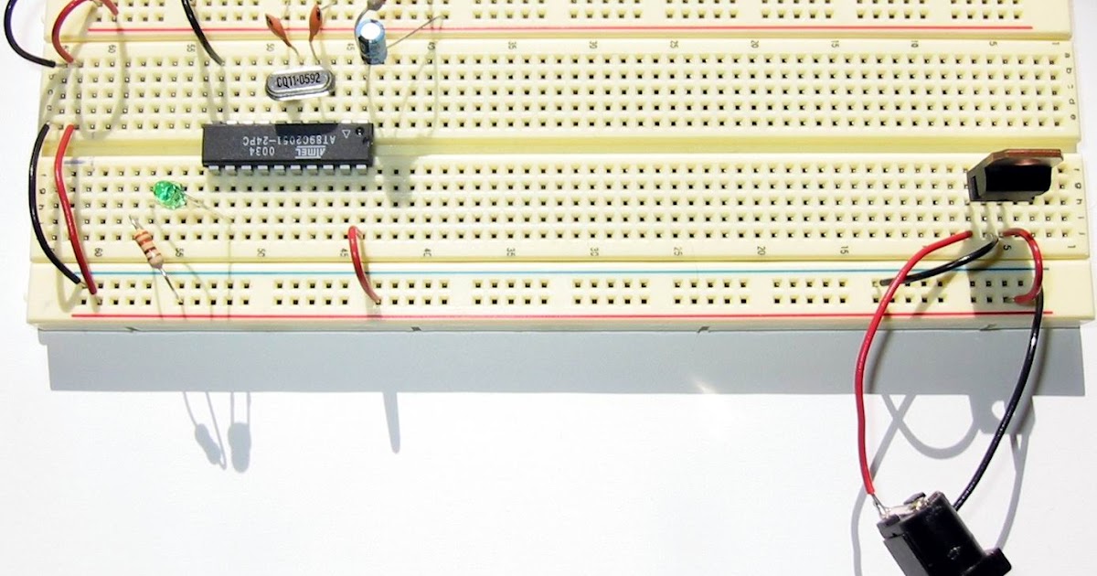
Apply a pea-sized amount of thermal paste to the CPU and put the heat sink on it.
You don’t need to spread the thermal paste because placing the heatsink on it will do the job.
Now, connect the CPU fan’s wires to the ATX and EPS connectors.
Installing the CPU fan is essential since most computers won’t start without them.
Now, you should connect the PSU cables and turn them on.
Remember to turn on the motherboard’s power, too.
If the CPU is okay, the fans start rotating.
You’ll also get a beep indicating there’s no RAM, which is fine because you don’t have any RAM installed.
5. Attach The RAM
Before installing the RAM, remember to switch off the power and unplug the PSU’s power cable.
This step is crucial because it may damage your components and hurt yourself if you don’t switch off the power.
Like with the CPU slots, you should also inspect the RAM slots to ensure they’re not damaged or contain any dust.
Installing the RAM sticks is uncomplicated because of the metal connectors that sit inside the slots only in one direction.
There’s no way you could get it wrong.
RAM slots have a clip at both sides that you need to press down and open the slots to accept the RAM sticks.
There’s no need to exert much pressure because they don’t move very far and are very easy to handle.
Align the RAM stick with the slot and gently push it down until it sits in the slot.
When it’s inside, the clips will go back into place, and you can hear a clicking sound.
You can power on the system through the steps stated above and see if it works.
You shouldn’t hear any beeps indicating faulty RAM, but you should hear the beeps that indicate a missing GPU.
If there are other RAM slots and sticks, you can repeat this process for each of them to verify they’re functional.
6. Install The Video Card
If you’re installing the graphics card for the first time, you may need to remove the covers on the backplate to expose the card’s display outputs.
Now, locate the first PCI-e X 16 slot near the CPU and push the clip on the back.
Line up the card with the slot and gently push it down until you hear a click showing the clip has closed.
If the card is connected to the backplate, you should fasten the screws that come with it.
Finally, connect it to the PSU using its dedicated power cables if the graphics card requires a separate power supply.
Breadboarding Tips
That’s pretty much everything involved in breadboarding the PC.
By this stage, you should find any faulty components within the computer via the beep codes or make sure that everything is functional.
There’s a helpful tip pointed out by users that may also help you find the issue.
If you can’t pinpoint the faulty hardware, try using a component from another system that you’re sure is working.
For example, if your system doesn’t POST with and without RAM, it may be because the RAM is faulty.
Borrow a functional RAM stick from another computer and try breadboarding with that.
This way, you’ll make sure you’ve ruled out all possible causes.
In addition, you want to make sure all the connections and cables are firmly in place because loose connections can prevent the system from POSTing or giving you any beeps.
You’ll need to make sure you’ve connected the speaker to the right plugs.
Otherwise, you won’t hear any beeps.
Another reason that can render all your effort useless is incompatible components.
Before even trying to install the new hardware into your mobo, make sure they’re compatible with each other by checking their specs.
The CPU, GPU, and power supply unit need to be compatible with each other and with the motherboard.
If none of these works, your motherboard is probably dead, and you need to replace it.
Finally, you can boot your system into BIOS to ensure it works with the basic software.
How To Boot The PC Into BIOS
The final step in pinpointing the culprit or making sure your new build is functional is to start the system into BIOS.
You may not have an operating system installed, so booting up the computer in BIOS will help you check things further.
At this stage, you’ll need to connect your keyboard and display to activate the BIOS menu.
Next, power on the computer and press your computer’s designated BIOS hotkey.
Each computer manufacturer has a different hotkey that boots the system into the BIOS mode.
This way, you’ll enter the BIOS menu and check if things are working properly.
Breadboarding Complementary Steps
As mentioned, breadboarding is a diagnostic tool that helps you detect faulty hardware or check newly-bought components to make sure they’re not DOA.
However, you can use other methods to ensure your components aren’t faulty or detect the issue before or after the breadboarding process.
Here are the most important ones:
1. Use The Correct Connector Cables And Sockets
It’s a known fact that loose connections can create issues that you may not even imagine.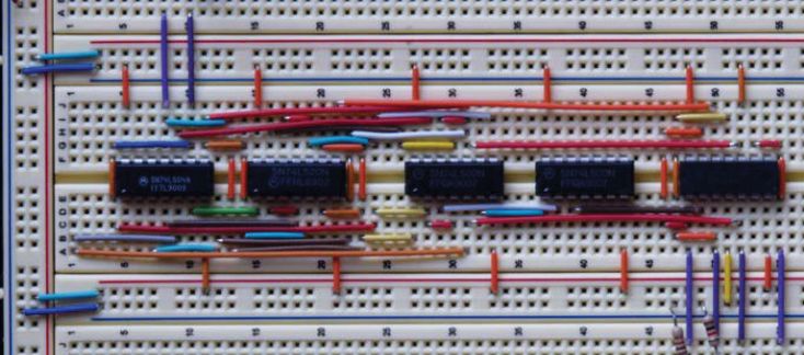
You’ll go around testing and swapping different components to no avail.
That’s a common mistake that newbies make.
Before doing anything, it’s essential to make sure all the connections are firmly in place.
That’s particularly the case with the CPU power connector.
Before connecting the CPU power connector, consult your motherboard’s user manual to ensure you’re using the correct sockets.
Otherwise, your system won’t POST.
One end of this cable should go into the CPU power socket and the other end into the PSU.
Some motherboards have eight pins on the CPU socket, while the power cable has four pins.
That’s okay, and you can safely plug it into the socket.
However, you should use the first four pins that are closer to the CPU.
Conversely, your PSU cable may have eight pins, while the CPU power socket has four pins.
In such cases, you should remove the cover over the other four pins and plug the 8-pin cable into the socket.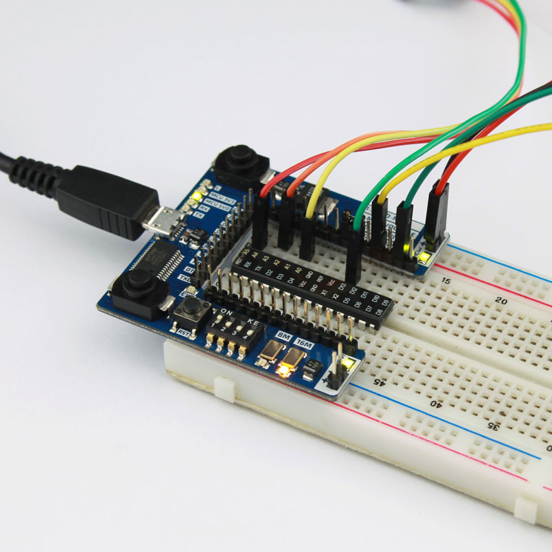
The same goes with the GPU connectors (if it needs any).
Check the graphics card’s user manual to see how many power connectors it needs and connect them properly.
While you’re at it, you may want to check the CPU fans, too.
These are essential components of any computer system, so much so that some computers don’t even boot up if the CPU fan isn’t connected.
Also, check if there are any cables or wires under the motherboard and remove them.
2. Apply Thermal Paste
Thermal paste plays a crucial role in keeping your system’s performance normal.
If the thermal paste on the CPU or GPU has worn off, you may be able to boot up your system, but it will shut down after a while because the components get too hot to operate.
Check the thermal paste and reapply it if necessary.
Applying the correct amount of thermal paste is also crucial.
It will overflow onto the CPU pins and cause serious damage if you use too much.
Conversely, if you apply too little thermal paste, it won’t cover the entire heat sink and can’t dissipate the generated heat effectively.
Also, make sure the heatsink is seated properly by checking all the sides.
3. Check Motherboard Standoffs
As mentioned before, if you don’t connect motherboard standoffs correctly, they come into contact with the case and cause electric shorts.
Double-check to see if every standoff aligns with the motherboard’s screw holes.
4. Make Sure Everything Is Seated Correctly
The CPU, GPU, and RAM sticks are the components you need to install properly.
Otherwise, your computer won’t boot or POST.
Sometimes faulty sockets may prevent these components from getting fully inserted.
In other cases, you may not have exerted enough pressure to push them down.
They all have clips that help them stay in place, and you can ensure they’re fully seated when you hear a click.
You should also look for any bent pins inside these sockets because many users have reported this issue as the underlying cause that their system didn’t POST.
Another thing you should consider about RAM sticks is how you arrange them.
Depending on whether you use a single- or dual-channel setup, you’ll need to insert the RAM stick into different slots.
In addition, while it may seem obvious, you may have forgotten to get the right RAM type, namely DDR3, 4, or 5.
It’s also essential to use RAM sticks from the same brand and with the same capacity and clock speed to avoid any incompatibility issues.
Building an 8-Bit CPU on a Breadboard
Sep 28, 2021
Years ago I came upon Ben Eater’s series of YouTube
videos
about building an 8-bit computer on a series of breadboards. I watched the
entire series but didn’t have the energy to complete the project myself. Then a
few months ago I decided to finally give it a go.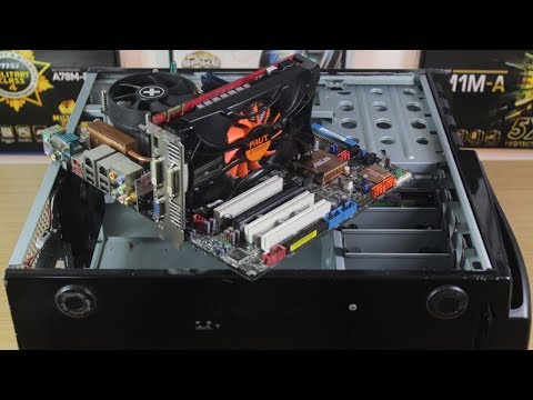
After toiling away with wires for around three months, spending way too much
money, and starting over twice, I finally completed my modified build of Ben’s
computer (which is the SAP-1 from the book Digital Computer
Electronics
by Albert Paul Malvino).
First Build
I first started the project building it exactly as Ben does in the videos and I
got pretty far until I hit a problem that most everyone does who starts this
project: sporadic issues. Things like signal noise and power distribution
troubles. No one is quite sure how Ben managed to avoid encountering them.
It was around when I started adding the program counter in my first build that
I began to have issues. My counter was counting twice for every clock tick. And
some other things were acting strangely and unpredictably. It turned out to be
a couple of different issues.
Bad Power Distribution
The original design has power input going to one of the breadboards and then
power is daisy chained to all of the others.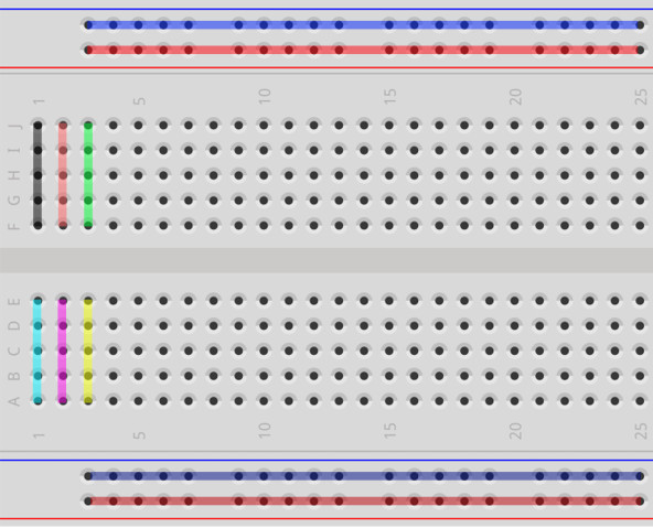 The chips farthest away from the
power input received lower voltages than the closest chips, sometimes even
dipping below the recommended voltage levels of the chips.
Floating Chip Pins
The original design uses 74LS TTL chips which, it turns out, should never have
their input pins floating. Instead you should tie either low or high. It
doesn’t really matter which; what’s important is that the inputs aren’t
floating somewhere in between. Although I did read that for lowest power
distribution you should tie the inputs to whatever will cause the outputs to be
high. For example, an AND gate should have both inputs tied high while a NOT
gate should have its input tied low.
Lack of Bypass Capacitors
The original design used capacitors only for achieving specific timing with the
555 chips. It is commonly recommended when designing circuits to place small
capacitors (called decoupling/bypass caps) near the power pins of integrated
circuits (like the 74LS chips) to help smooth out power line noise. If the
voltage has a spike the capacitor will absorb it and if the voltage drops the
capacitor will provide enough to keep the voltage to the chip stables.
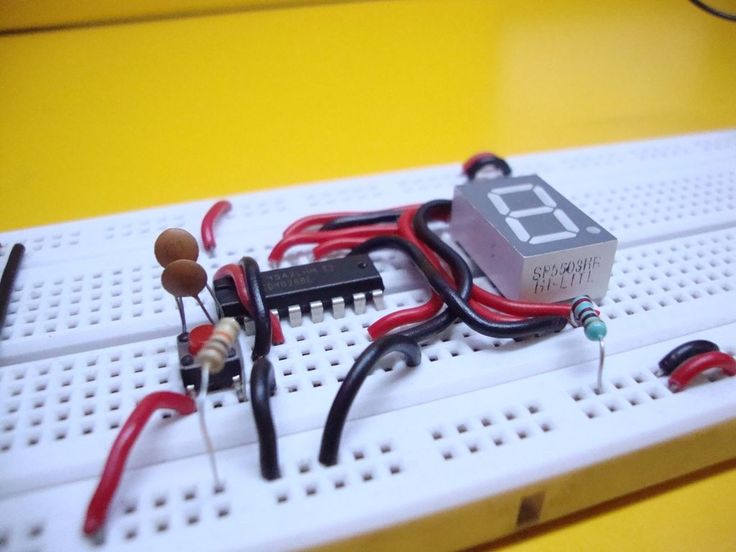
Here’s an example of the original clock module I built which has the issue of
floating chip pins and a lack of capacitors near the power pins.
Here’s my original build of the A/B/ALU modules where you can see the
daisy-chaining down the right side, with the power input in the upper-right
corner.
I did make some modifications from Ben’s design from the beginning, mainly
concerning LEDs. The original design often connected LEDs directly to output
pins of the chips because the 74LS chips have internal resistors on the
outputs. That’s technically okay but can lead to subtle troubles that are hard
to find. It was drilled into me long ago that you always put current-limiting
resistors on LEDs so that’s what I did.
I also used LED bars because I found it annoying trying to line up individual
LEDs in a row that looked clean. I also think the bars look really cool.
Second Build
When I started seeing unpredictable behavior (a terrifying concept), I decided
to start over and rebuild. I could have made the modifications in-place but it
would have been annoying, and I’m more of a burn-it-and-start-anew kind of
person anyway.
I decided to start over, addressing the floating inputs and lack of bypass
capacitors, as well as another idea I had.
Central Reset and Clock Lines
In addition to fixing the problems I had in the first build, I also wanted to
fix the problem of messy wiring. I had the idea to add four extra lines down
the center next to the bus: two clock, one reset, and one inverted reset. The
reset and clock lines go to nearly every module so it was much cleaner this
way.
Here is the rebuilt clock module which demonstrates all of the changes:
I went a bit overboard and starting putting the bypass capacitors right next to
the ICs which ended up eating precious breadboard space.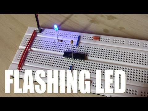 It became increasingly
annoying because it was no hard to route wires in between the chips.
Third Build
I had nearly everything wired up and in place when I decided to start over yet
again. I had some new ideas (again) and I wanted to start clean rather than try
to modify in-place. Why do I do this to myself?
74HC Chips
The 74HC chips are CMOS instead of TTL and consume (a lot) less power as a
result. They also tend to be less noisy.
Central Power Rail
I still had the issue of bad power distribution through daisy chaining and it
occurred to me that I could do with the power lines what I did with the clock
and reset lines: run them down the middle.
Better DIP Switches
The ones I had were hard to switch and kept popping out because they weren’t
made for breadboards.
Relocate the Bypass Capacitors
I definitely wanted to have bypass capacitors but putting them physically next
to the chips took up too much space. It was easier and near as good to put
them next to the chip’s power wires instead.
Wire Control Lines First
I realized that if I put down the yellow control wires first (and to a lesser
extent the reset and clock wires), I could run the blue bus wires on top of
them which would pin them down and limit their freedom to move around and cause
problems.
Make Schematics Before Building
The process of hook things up for the first two builds was essentially looking
at datasheets, making note of which pins connected to which pins, laying things
out in my head, and then wiring it up. That led to mistakes as well as unclean
wires because I didn’t have a big picture view.
I started drawing schematics in KiCad first before hooking anything up which
let me lay things out in a way that made better physical sense (e.g., trying to
avoid crossing wires from the bottom of the boards to the top), and it was
easier to reference a single schematic than multiple datasheets.
Complete and Test Each Module Fully
This one seems obvious but if you build everything in the order that Ben does, you’re often leaving
modules incomplete until later. Having already built the thing twice before, I had a good idea of
how everything worked as a whole so I could finish each module fully from top to bottom, right side
first (except for the clock which is on the left side).
As an example, after the clock was finished I hooked up the Program Counter in its entirety: reset, clock, control,
and bus. Ben leaves the control lines for when he discusses control logic and the bus lines for when he discusses the
bus. I’m sure he did it that way for pedagogical purposes, but it makes for a bit of a mess having to go back and
retrofit a module.
I set up the bus and the control LEDs immediately so that I could hook each module up fully before moving on.
556 Timer
Why use two chips when one will do?
256 Bytes of RAM
16 bytes of RAM seemed limiting.
Arduino Nano for Programming
I thought it would be nice to be able to program the thing with an Arduino
instead of using the DIP switches all the time, but I never got around to doing
it.
With that I began anew.
I wired from top to bottom, right side first, control signals always first.
That ensured that all of the wires overlapped appropriately. (I’m still not
happy with the ALU wiring but I got tired of bending wire.)
You can see the awesome DIP switches that not only look similar to the ICs, but
they fit nice and snug into the breadboard.
And then I took a break for a month because I was on my third build and I was
absolutely sick of cutting wire. But finally I mustered the energy to finish
it, mostly because I kept having friends ask me what the hell I was building
and I couldn’t really demonstrate anything interesting.
Conclusion
I loved this project and it was immensely satisfying to actually finish it. I
had been following Ben’s work on YouTube for years but never started. Then I
started and restarted and restarted again. And finally I finished it.
However, I realized near the end of the project that while I enjoyed the
learning and the designing and the logic, the constant cutting and routing of
wire was incredibly tedious. Small mistakes took a lot of work to fix and I was
hesitant to try new things because of the effort involved. And this was on a
breadboard where mistakes are easily fixed compared to doing rework on a
printed circuit board.
Of the countless hours I spent on the project, I would guess that 90% of it was
cutting wire, shaping wire, and debugging wire.
In fact, there’s a bug present in the above video. For some reason it only counts to
64 and then it restarts. And I don’t have any energy left to hunt down the
issue. Maybe one day.
All of that is to say that I enjoy logic and hardware but the lack of flexibility
is frustrating (coming from someone who writes software for a living). That has
led me to start dabbling in FPGAs, and also recreating the computer on the Game
Boy (more on that at a later date).
Last Edited: Dec 20, 2022
Modeling and prototyping
Modeling and prototyping
- Material Information
-
-
5th grade
-
6th grade
- Description
- Heading parameters
Description
Fundamentals of 3D modeling, development of spatial thinking, technology of volume-spatial layout using various materials (cardboard, paper, plastic, etc. ), creation of pop-up layouts.
February 2023
| Mon | W | Wed | Thu | Fri | Sat | Sun |
|---|---|---|---|---|---|---|
| 1 | 2 | 3 | 4 | 5 | ||
| 6 | 7 | 8 | 9 | 10 | eleven | 12 |
| 13 | 14 | 15 | 16 | 17 | 18 | 19 |
| 20 | 21 | 22 | 23 | 24 | 25 | 26 |
| 27 | 28 |
Message. Pilot project. This form is not intended for receiving applications from citizens in accordance with Federal Law No. 59-FZ of May 2, 2006 “On the Procedure for Considering Applications from Citizens of the Russian Federation” and provides an opportunity to send an electronic message as part of a pilot project to introduce a “Single Window of Digital Feedback”. The response to the message will be sent no later than 8 working days after the day of its registration, and for certain topics — in a shorter time.
Back to top
Every year, employers submit to the territorial body of the Pension Fund the lists of persons retiring in the next year and models of pension files for each future pensioner.
The layout includes a set of documents — a passport, SNILS, work book, military ID, etc. The full list of documents is published on the PFR website.
In a number of regions, it is possible to transfer models of pension files through Kontur.Extern. Below is a list of regions and UPFR codes to which layouts should be sent.
- 01 region (001-) The code for layouts is the same as the code where the organization is located
- 02 region (002-) Code 002-999
- 03 region (003-) The code for layouts is the same as the code where the organization is located
- 04 region (004-) The code for layouts is the same as the code where the organization is located
- 05 region (017-) The code for layouts is the same as the code where the organization is located
- 08 region (006-) The code for layouts is the same as the code where the organization is located
- 09 region (008-) The code for layouts is the same as the code where the organization is located
- 10 region (009-) The code for layouts is the same as the code where the organization is located
- 11 region (007-) Code 007-111
- 12 region (010-) The code for layouts is the same as the code where the organization is located
- 13 region (011-) Code 011-111
- 14 region (016-) The code for layouts is the same as the code where the organization is located
- 15 region (012-) The code for layouts is the same as the code where the organization is located
- 16 region (013-) Code 013-111
- 17 region (018-) The code for layouts is the same as the code where the organization is located
- 18 region (019-) Code 019-919
- 19 region (014-) The code for layouts is the same as the code where the organization is located
- 20 region (020-) The code for layouts is the same as the code where the organization is located
- 21 regions (015-) Code 015-1XX*
- 22 region (032-) The code for layouts is the same as the code where the organization is located
- 23 region (033-) The code for layouts is the same as the code where the organization is located
- 24 region (034-) Codes 205-062; 205-063; 205-064
- 25 region (035-) Code 035-900
- 26 region (036-) The code for layouts is the same as the code where the organization is located
- 27 region (037-) Code 037-111
- 28 region (038-) The code for layouts is the same as the code where the organization is located
- 29 region (039-) The code for layouts is the same as the code where the organization is located
- 30 region (040-) Code 040-111
- 31 regions (041-) Code 041-9XX*
- 32 region (042-) The code for layouts is the same as the code where the organization is located
- 33 region (043-) The code for layouts is the same as the code where the organization is located, only the last digit changes to 1.
- 34 region (044-) The code for layouts is the same as the code where the organization is located
- 35 region (045-) Code 045-9XX*
- 36 region (046-) Code 046-9XX*
- 37 region (047-) The code for layouts is the same as the code where the organization is located
- 38 region (048-) Code 048-111
- 39 region (049-) Code 049-111
- 41 regions (022-, 051-) The code for layouts is the same as the code where the organization is located
- 42 region (052-) The code for layouts is the same as the code where the organization is located
- 43 region (053-) The code for layouts is the same as the code where the organization is located
- 44 region (054-) The code for layouts is the same as the code where the organization is located
- 45 region (055-) Code 055-200
- 46 region (056-) The code for layouts is the same as the code where the organization is located
- 47 region (057-) Code 057-057
- 48 region (058-) The code for layouts is the same as the code where the organization is located
- 49 region (059-) The code for layouts is the same as the code where the organization is
- 50 region (060-) The code for layouts is the same as the code where the organization is located
- 51 regions (061-) The code for layouts is the same as the code where the organization is located
- 52 region (062-)Code 062-100
- 53 region (063-) The code for layouts is the same as the code where the organization is located
- 54 region (064-) Code 064-111
- 55 region (065-) The code for layouts is the same as the code where the organization is located
- 56 region (066-) The code for layouts is the same as the code where the organization is located
- 57 region (067-) The code for layouts is the same as the code where the organization is located
- 58 region (065-) Code 068-111
- 59 region (069-,023-) Code 069-9XX, 023-9XX
- 60 region (070-) The code for layouts is indicated at the pensioner’s place of residence
- 61 regions (071-) The code for layouts is indicated at the pensioner’s place of residence
- 62 region (072-) Code 072-9XX*
- 63 region (077-) Code 077-100
- 64 region (073-) Code 073-9XX*
- 65 region (074-) The code for layouts is the same as the code where the organization is located
- 66 region (075-) The code for layouts is the same as the code where the organization is located
- 67 region (076-) Code 076-2XX*
- 69 region (078-) The code for layouts is the same as the code where the organization is located
- 71 regions (081-) The code for layouts is the same as the code where the organization is located
- 72 region (082-) Code 082-111
- 73 region (083-) Code 083-100
- 74 region (084-) The code for layouts is the same as the code where the organization is located
- 75 region (085-) Code 085-901
- 76 region (086-) Code 086-200
- 77 region (087-) The code for layouts is the same as the code where the organization is located
- 78 region (088-) Code 088-088
- 79 region (031-) The code for layouts is the same as the code where the organization is located
- 86 region (027-) Code 027-9XX*
- 89 region (030-) The code for layouts is the same as the code where the organization is located
- 91 regions (091-) The code for layouts is the same as the code where the organization is located
- 92 region (092-) The code for layouts is the same as the code where the organization is located
* — the code for layouts of pension cases differs from the PFR code where the organization is registered by the fourth digit (for example, 21 regions (015-), code for layouts 015-1XX: the organization reports to 015-002, sends layouts to 015 — 1 02; or reports to 015-023, layouts to 015- 1 23).
Features
To send layouts of pension files, you need to conclude an additional agreement to subscribers of 02, 41, 47, 49, 56, 66, 71, 74, 78 regions and subscribers in Belgorod in 31 regions (all other subscribers in 31 regions do not need to enter into an additional agreement need to).
Form of agreement for the Republic of Bashkortostan (region 02)
Form of agreement for Belgorod (31 regions)
Agreement form for the Sverdlovsk region (region 66)
Form of agreement for the Sverdlovsk region (UE) (region 66)
Form add. agreements for the Sverdlovsk region (66th region)
Form of agreement for St. Petersburg and the Leningrad region (regions 78 and 47)
For regions 02 and 56: in addition to an additional agreement, it is necessary to pack all files of scanned documents for one insured person into one zip archive, the name of which must be equal to the SNILS number of the insured person.