Motherboard | Components | Function
Want create site? Find Free WordPress Themes and plugins.
The motherboard is the main system board for the computer and connects all of the internal hardware components. This lesson will take a look at various components which are built into the motherboard. This lesson will also look at the expansion slots used to add hardware components to a system. The lesson finishes up with a discussion of the BIOS.
Lesson Objectives
By the end of this lesson, you will be able to:
- Identify the components on a motherboard.
- Identify the function of the Northbridge.
- Identify the function of the Southbridge.
- Recommend a motherboard for a given scenario.
- Identify appropriate BIOS settings.
- Differentiate expansion slots on the motherboard.
Instruction
A computer technician must have a strong understanding of the components used within a computer system. Understanding the purpose of each component provides the foundation of knowledge required to understand the operation of a computer system.
Motherboards
The motherboard is the largest printed circuit board, and every electronic device has one including computers, cell phones, printers, cars, and even toasters.
The motherboard determines the capabilities and limitations of a computer system. Every component on a computer system plugs into the motherboard is controlled by it and depends on it to communicate. The motherboard houses the following components:
- Central Processing Unit (CPU) – performs all basic arithmetic, logical, control, and input/output operations
- Chipset – manages the data flow between the computer’s processor, its memory and any peripheral devices attached
- Buses – a pathway that transfers data between components within a computer
- Random Access Memory (RAM) – a temporary form of computer data storage that allows fast access to data.
 RAM is volatile and requires power to keep data accessible.
 - Expansion slots – provide expansion capability to add hardware components beyond what was originally installed
- Ports – provides an interface between the computer and a peripheral device such as a mouse, keyboard, or printer
All of the above components are labeled in Figure 1.
Figure 1: Motherboard Diagram with all components labeled
There are several components that comprise a motherboard. In this lesson, the following main components will be highlighted:
- System Clock
- Chipset
- Expansion Cards and Slots
- Front Panel Connectors
- Basic Input/Output System (BIOS)
- Complementary metal–oxide–semiconductor(CMOS)
- System bus with expansion slots
- Bus Structures
System Clock
Think of the system clock as the heartbeat of the motherboard.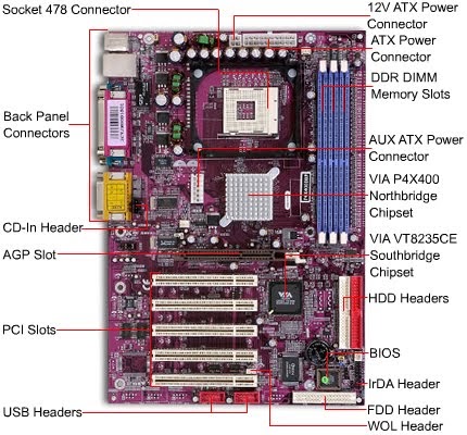 It sets the speed of all other components like the processor, memory, and buses. It has a base speed that is measured in hertz (Hz), but computers run in megahertz (MHz) or gigahertz (GHz).
Chipset
The chipset determines how system hardware and buses interact with the CPU and other components. It also determines how much memory can be added to a motherboard and what type of connectors the motherboard will have.
Current chipsets are made up of two distinct components – the Northbridge (NB) and Southbridge (SB).
The Northbridge controls RAM, the processor, and the Accelerated Graphics Port (AGP) video slot. It also regulates the speed the CPU can communicate with the components.
The Southbridge controls everything else connected to the computer including communication between the CPU and the expansion ports (hard drives, sound card, Universal Serial Bus (USB) ports, and other I/O ports).
Figure 2: Components of a chipset
The Northbridge (labeled NB) and Southbridge (labeled SB) are both shown on a laptop motherboard in Figure 2.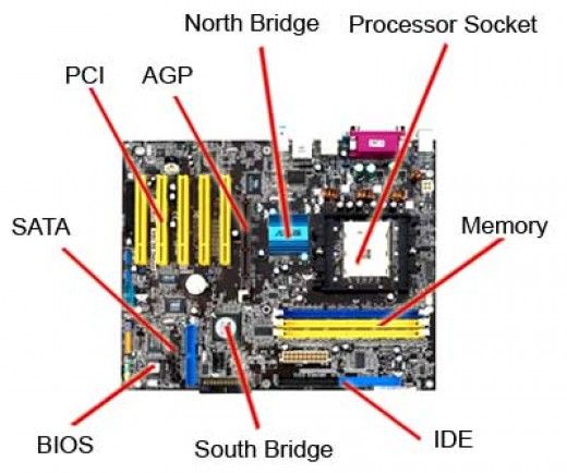
Expansion Slots
Expansion slots allow the installation of extra components. Peripheral Component Interconnect (PCI), are used to install network cards, sound cards or modems.
AGP slots accommodate video cards with additional capabilities and PCI express (PCIe) cards to connect host bus adapters (HBAs) for expanded storage and cards for additional USB and Firewire ports.
Figure 3: Expansion slots on a motherboard
Riser Cards
A riser card physically extends a slot so multiple cards can be plugged into a motherboard. The expansion cards will actually be turned 90 degrees to the motherboard. This allows cards to fit into a smaller space. Riser cards are usually only used in low-profile or slimline cases.
Figure 4: Multiple slot riser
The one slot on the motherboard can now accommodate multiple expansion cards.
Figure 5: Multiple slot riser seated in a motherboard
Other Slots
Other slots encountered on the motherboard include the audio/modem riser (AMR) and the communications and networking riser (CNR). These two slots do basically the same thing with the CNR having a few additional functions. They were created to hold modems, network cards, and sound cards. You will seldom see these used on today’s motherboards.
As shown in Figure 6, the 30-pin AMR slot is much smaller than a PCI expansion slot. The 30-pin interfaces accommodate two formats making various audio/modem and audio network combinations possible.
Figure 6: Audio/Modem Riser (AMR) slot next to white PCI slot
The AMR evolved into the CNR adding LAN and home networking functions.
Figure 7: Communications and networking riser (CNR) slot
Front Panel Connectors
Front panel connectors are used to connect the power LED (light emitting diode) light on the front of the case to a hard drive, a small internal speaker for testing, the power button, and the reset button. There may also be additional LED lights for USB, Firewire and audio devices.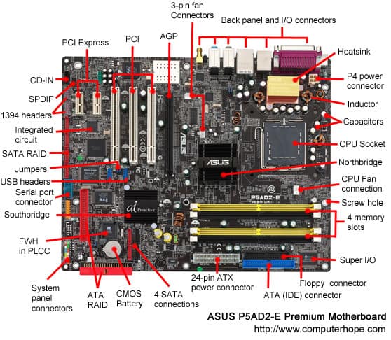
All of the front panel connectors from the case get plugged into tiny pins on the motherboard. The layout of the pins varies from motherboard to motherboard, although they are usually grouped together and color-coded. You may or may not use all of the connectors.
Sometimes the power LED has a blank pin between the two wires. You can buy an adapter to change the pin layout or simply cut the connector to accommodate the pins.
It is important to note that the reset jumper must be attached to the pins, in the correct order, before the computer will start. If nothing happens when you turn on the computer for the first time, check that the reset jumper was attached correctly.
You may view a visual installation of connectors to the pins on a motherboard at the following URLs:
- MSI HOW-TO Install front panel connectors (JFP1) (1:09)
- Instalacion del Panel Frontal (3:46)
It is important to remember that each motherboard is different, and it is important to look up the proper connections in the motherboard manual.
Figure 8: Connection schematic using a sample motherboard front panel connector
BIOS – Basic Input/ Output System
The Basic Input/ Output System (BIOS) may be referred to as the System BIOS or ROM (Read Only Memory) BIOS. The BIOS holds the motherboard’s firmware which is nothing more than a set of instructions. It is the first software run when the computer is powered on.
The fundamental purpose of the BIOS is to initialize and test the system’s hardware components and to load the operating system. The BIOS provides a consistent way for applications and the operating system to interact with I/O devices like the keyboard, mouse, display, and other connected devices.
BIOS and CMOS
Working with the BIOS is a chip known as the complementary metal–oxide semiconductor (CMOS). The CMOS holds the settings you selected in the BIOS. CMOS is volatile in nature. That means it must be supplied with continuous power that is supplied by a battery. If the battery runs down settings will be lost.
Figure 9: CMOS Battery
The BIOS has a menu-based user interface to make changes such as:
- Configure hardware
- Make changes to I/O ports
- Set the system time
- Enable or disable system components
- Set voltages for the CPU and memory
- Set the boot sequence
- Control fan speeds
- Set a BIOS and system password
- Enable or disable virtualization support
Users can set various password prompts, such as a password for securing access to the BIOS user interface functions itself and preventing malicious users from booting the system from unauthorized peripheral devices.
Figure 10: Phoenix BIOS chip
BIOS Options
The first thing the computer does when it is turned on is to run a diagnostic program called the Power on Self-Test or POST. The POST checks that all the motherboard components are functioning and can communicate with each other.
The BIOS can be accessed at system startup with a particular key sequence. This is usually the delete key or the F2 key, but different manufacturers may have a different sequence to press.
Figure 11: CMOS Setup Utility
Built-in tools can monitor the following:
-
- Temperature
- Fan Speeds
- Intrusion detection
- Voltages
- Clock
- Bus speeds
To see additional screenshots of various options that can be viewed and/or changed in the BIOS setup, browse to MSI 790GX-G65 Motherboard Reviews and scroll down to the bottom of the page.
The BIOS software is stored on a non-volatile ROM chip on the motherboard. This means the chip does not lose its contents even if there is no power going to the BIOS.
Using the BIOS menu, you are able to change hardware configurations such as the order in which the PC boots – floppy drive, hard drive, CD-ROM, USB.
The ROM BIOS is commonly called the computer’s firmware. Firmware used to be hardcoded on the chip and could not be changed without replacing the chip. Most modern devices can be upgraded when new features are added. This process is called flashing the BIOS.
Newer BIOS chips are made of Electrically Erasable Programmable Read Only Memory (EEPROM) chips. This type of chip allows the content of the BIOS to be rewritten without removing the chip from the motherboard. This way the BIOS software can be easily upgraded to add new features or fix bugs.
So what happens if you set a BIOS password and then forget what it was? The BIOS and system passwords can be easily erased along with all the other user settings. This can be done by removing the battery, waiting a few seconds and then putting it back in.
The most common way is to locate the CMOS reset jumper. Simply move the jumper to the enabled position (jumper on pins 2 and 3), and turn on the computer which sends an electrical signal to erase the CMOS. Be sure to then move the jumper back to the disabled or default position (jumper on pins 1 and 2). The CMOS is now back to the factory default settings.
Figure 12: CMOS Reset jumpers
EFI and UEFI
Starting in 2011, the BIOS was replaced on some motherboards with a more complex Extensible Firmware Interface (EFI) or the Unified Extensible Firmware Interface (UEFI). This new BIOS type was introduced to provide more diagnostic and repair tools to the computer and provide a more efficient interface between the operating system and the components.
Initially made for the Itanium architecture, it is now available for x86 and x64 platforms and provides legacy support for BIOS services. It can support remote diagnostics and repair of computers, even without an operating system
Figure 13: Extensible Firmware Interface (EFI)
Documentation
It is very important to document the settings you have changed in the CMOS. This way if something ever happens, like the CMOS battery runs down, you have a record of what the previous settings were and how to reset them.
It is recommended that you tape your documentation inside the case so anyone that works on that computer has a copy of your configuration.
Keep well-labeled, written record of:
- All changes you make to CMOS
- Records of hardware and software installed
- Network settings
Keep documentation up to date and in a safe place. Also, the document before you flash or replace the BIOS chip.
Bus Structures
A bus can be defined as a channel or path between components. The speed of the bus has a lot to do with the speed of the computer.
There are a lot of incredibly complex components in a computer, and all of these parts need to communicate with each other in a fast and efficient manner. Otherwise, the amazing speed and capabilities of each individual component is lost in the whole.
Typical Bus Structures
There are two key buses in a computer: the system bus and the shared bus.
The system bus is also called the local bus or front side bus. This bus connects the CPU to the system memory. It is one of the most important buses in the system. The faster the processors can move information in and out of the memory, the faster computers operate. When selecting a motherboard, find one with the fastest system bus possible.
The shared bus is what connects all the other components to our computer and moves information around inside the motherboard.
The shared bus connects the Industry Standard Architecture (ISA), Extended Industry Standard Architecture (EISA), PCI, and PCIe, USB, and Firewire buses together. This is done through bridges, which are part of the computer’s chipset. This bridge acts as a traffic cop, integrating the data from the other buses into the system bus. This bridge lets multiple devices access the same path to the CPU and system memory.
Most chipsets have two bridges: the Northbridge and the Southbridge. You can see in Figure 13 that the Northbridge controls the CPU, memory, and the AGP slot for video. The front side bus, memory bus, and AGP bus all connect to the Northbridge.
The Southbridge basically controls everything else. Hard drives, CD players, DVD players, PCI bus, and I/O ports are all connected to the Southbridge. The Southbridge regulates what bus and how much information can be passed to the Northbridge.
Figure 14: Bus structure
Summary
The motherboard is considered the nervous system of a computer. Everything that is not built into the motherboard is connected to it in slots or through ports. Its main components are the system clock, CPU, chipset, RAM, ROM BIOS, CMOS, power supply, ports, and the system bus with expansion slots.
Information stored in the BIOS is powered by the CMOS battery. Without the battery, the BIOS settings would have to be reset each time the host is booted. Information, such as the type of hard drive, the boot order, date and time, is stored in BIOS and is used by the host when it is booting.
Did you find apk for android? You can find new Free Android Games and apps.
CompTIA A+ Motherboard Diagram 2022: What to Know
CompTIA A+ motherboard diagram is the principal thing that CompTIA A+ test-takers need to deeply understand for the purpose of maximizing their score. In this article, we will provide you with everything you need to know about this knowledge area.
Let’s get started with our free CompTIA A+ practice test to pass the actual exam with a flying score.
General Information of CompTIA A+ Motherboard Diagram
Motherboard (Motherboard) is also known by other names such as MB, mainboard, backplane board, baseboard, main circuit board, planar board, system board, or on Apple computers it is Logic board. The motherboard is a circuit board that plays the role of the foundation of a computer set, located in the center of the case. It distributes power to the CPU, RAM, and all other hardware components of the computer. Most importantly, the motherboard creates the link between these components.
Structure
The printed circuit board of the motherboard has a slightly different structure than the printed circuit board of other commonly found electronic devices. Most printed circuit boards in simple circuits have a double-sided structure (front and back) to accommodate the paths on them.
Because there are many paths operating with different frequencies, (as a general rule) the board must be designed with paths that do not interfere with each other, this is a difference that makes the board design of motherboards different from ordinary motherboards. The motherboard, because it contains many components with large paths, is designed with 3 to 5 layers (or even more): In addition to the front and back two layers, there are lines in the middle of the board. guide.
Functions of Motherboard
- The process of booting the motherboard after power-on
- Binding components on a computer system together
- BUS speed change control to suit different components
- Power management for components on the Main
- Provide a master clock (Clock pulse) to synchronize the operation of the whole system
Main components
- Chipset (including southbridge and northbridge): Playing a very important role, the chipset will bring data from the hard drive, through memory, then to the CPU and ensure peripherals and expansion cards are still available.
 can “communicate” with the CPU and other devices.
 - BIOS: This is the basic I/O device, playing an equally important role as the chipset in each main server. This device contains the working parameters of the system. BIOS will be soldered and glued directly to the main server or plugged into a socket for users to easily disassemble.
- Socket: Is the number of CPU pins on the mainboard, the socket type of the CPU you want to buy must be compatible with the supported mainboard.
- CPU: The standard slots for AMD and Intel processors are different, so you can’t plug this company’s processor into the mainboard that supports the store’s processor. Store processors will use different slots, so in many cases, you won’t be able to upgrade either.
- Bu system: Indicates the maximum operating frequency of the data communication line of the CPU that the main supports. The high-speed bus will also support lower bus processors.

- ISA slot: To plug in additional expansion boards such as video and audio boards, etc. Currently, the ISA slot is no longer integrated into the motherboard.
- PCI slot: Used to install additional communication devices with the computer such as sound cards, internal modems, etc.
- PCI Express slot: Supports 30 years more bandwidth than the PCI standard, capable of completely replacing both PCI and AGP slots.
Read more >> CompTIA A+ Cable Types & Connectors with Their Purposes
Motherboard Form Factors
The form calculated could be an equipment plan perspective that characterizes and endorses the estimate, shape, and other physical details of components, particularly in hardware. It may moreover characterize a whole framework, as in a computer shape figure. Computer chassis are outlined to oblige particular frame components, and knowing these common standard shape variables is basic for a CompTIA A+ technician:
ATX (Advanced Technology eXtended)
Advanced Scaling Technology, aka ATX, is the most common element for desktop cases and motherboards. It’s a standard introduced by Intel as a replacement for the old AT design. It’s an evolutionary design that builds on the previous Advanced Technology (AT) model by improving the outline of the case, power supply, and motherboard. With better use of space and resources, ATX is quickly becoming the default form factor for most new PC systems. Today, the industry accepts the ATX form factor as the standard.
The ATX was a major alter from AT motherboard plans and got to be the default frame calculation for most modern frameworks because it progressed back for I/O gadgets and innovation. processor innovation, making it a part less demanding to include or remove components. ATX is additionally more prudent than past frame components.
The modules on ATX motherboards are outlined to work together more effectively due to the more ideal situation of each component. With the drive and control supply found in a more functional area, the motherboard will be less demanding to associate. By decreasing the motherboard’s cable length, the chance of information debasement and EMI (stands for electromagnetic interference) is diminished.
An extra highlight of ATX motherboards is the situation of the control supply fan. Discuss is blown straightforwardly into the processor and development card for moved forward cooling and diminished clamor. An extra ATX property could be a delicate switch or delicate control included.
The delicate switch is controlled by the OS, which gives a slight control when the framework is turned off by the control switch. When utilizing the control switch to close down more seasoned frameworks, the control is all of a sudden turned off, frequently causing mistakes amid reboots and putting an extra push on the motherboard.
ITX (Information Technology eXtended)
ITX – Information Technology eXtended, most commonly known as Mini-ITX version – is a small 170×170 mm mainboard, marketed in 2001 by VIA Technologies for use in computer systems to Compact size tables. Initially, the ITX mainboard standard was born with the aim of maximizing mobility and reducing the overall cost, but due to a combination of reasons, the latter cost increased.
Basically, the case system using Mini-ITX can be considered a desktop computer with mobile features thanks to its surprising compactness. In conditions that often have to be on the move and need the power of a desktop system that a laptop can hardly handle, the ITX case is a great solution. Playing live games (online) or 3D design, doing graphics tasks, etc. needing the highest stability of the system will need a compact case using an ITX mainboard.
In addition to that optimal purpose, the ITX mainboard rigs are also one of the “hardcore” hobbies of technology enthusiasts. Imagine a system as compact as possible (with the condition of being portable) that is “stuffed” with toys like a large case but still has to ensure heat dissipation, which requires a lot of knowledge. Investing and arranging components is not small.
Motherboard Connector Types
Motherboards utilize extension spaces to supply bolster for extra input/output (I/O) gadgets and high-speed video/graphics cards with the foremost common extension openings being PCI Express (also known as PCIe for short).
PCI Slots (Peripheral Component Interconnect)
PCI is an acronym for the phrase Peripheral Component Interconnect, which is a concept to refers to the communication standard between computer hardware components. They determine the compatibility between different parts of the computer system. Usually, we often write to the PCI standard for motherboards, RAM, graphics cards, sound cards, network cards, mice, keyboards, and computer speakers,… Different PCI standards give transfer speeds. Load different data. In which, PCIe is the communication standard with high data transmission speed.
PCI was introduced by Intel in 1992. The PCI bus comes in both 32-bit (133MBps) and 64-bit versions and is used to attach hardware to computers. Although commonly used in computers from the late 90s to the early 2000s. PCI has been replaced by PCI Express. Versions were released in 1993 to version 2.0. And 1995 with PCI 2.1, as an extension to the ISA bus. Unlike ISA and other previous expansion cards. PCI follows the PnP specification and therefore does not require any jumpers or embedded switches.
PCIe (PCI Express) Slots
PCIe or PCI Express is a generation of PCI interface standards with higher data transfer rates than conventional PCI. They usually refer to the connections between the expansion card components, the computer RAM, and the computer motherboard. PCIe 4.0 is the latest communication standard, and the highest data transfer rate available today. PCIe 4.0 supports maximum speeds up to 16GT/s, a bandwidth of 64GB/s. And PCIe 3.0 is the most popular communication standard between computer components.
PCIe could be a high-speed serial computer development transport standard outlined to supplant the more seasoned PCI transport guidelines. It is the common motherboard interface for PC’s design cards, difficult drives, SSDs, WiFi, and Ethernet equipment associations. PCIe has advancements over the more seasoned, counting higher greatest throughput I/O stick tally and littler physical impression, better way execution scaling, more nitty mistake discovery and various components, and local hot-swap usefulness.
More later forms of the PCIe standard give the equipment back for I/O virtualization. PCIe openings are accessible in 4 specific sorts: x1, x4, x8, & x16. (Each x alludes to an I/O path.)
Riser Cards
A riser card may be a printed circuit board that picks up a large number of flag lines (regularly used) through a single connector (as a rule an edge connector) on a motherboard and conveys them through devoted connectors on the card. Riser cards are regularly utilized to permit extension cards or different ports accessible to a framework encased in a low-profile case where the stature of the case does not permit the opposite situation of the full-height extension card.
Socket Types
In computer equipment, a CPU attachment (CPU space) contains one or more mechanical components giving mechanical and electrical associations between a chip and a printed circuit board. This permits for putting and supplanting the CPU without patching. Common attachments have maintenance clips that apply a steady constraint, which must be overcome when a gadget is embedded.
For chips with numerous pins, zero insertion force (also known as ZIF) attachments are favored. Common attachments incorporate PGA (stands for the Pin Grid Array) or LGA (stands for the Land Grid Array). These plans apply a compression constraint once either a handle (PGA sort) or a surface plate (LGA sort) is put into place. This gives predominant mechanical maintenance while maintaining a strategic distance from the chance of twisting pins when embedding the chip into the attachment.
ZIF (also known as the Zero insertion force) may be a sort of coordinated circuit (IC) or electrical connector that requires an exceptionally small drive for inclusion. With a ZIF attachment, a lever or slider on the side of the attachment is moved, pushing all the sprung contacts separated so that the IC can be embedded with an exceptionally small drive, for the most part, the weight of the IC itself is adequate and no outside descending drive is required.
The lever is then moved back, permitting the contacts to shut and grasp the pins of the IC. ZIF attachments are much more costly than standard IC attachments which tend to require a larger board due to the space taken up by the lever instrument. Ordinarily, they are utilized when there’s a great reason to do so.
The LGA could be a bundling innovation with a rectangular lattice of contacts on the underside of a package. The LGA plan employs spring-loaded lands within the processor attachment that interface to bumps on the posterior of the processor. The number of lands within the processor attachment is utilized for the numeric portion of the attachment title.
For illustration, LGA 775 has 775 lands within the processor attachment.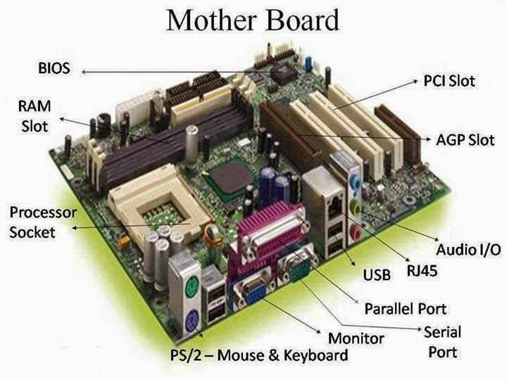 Not all columns and columns of the framework got to be utilized. The contacts can either be made by utilizing an LGA attachment, or by utilizing patch glue.
SATA & IDE
Serial ATA could be a computer transport interface that interfaces transport connectors to mass capacity gadgets such as difficult disk drives, optical drives, and solid-state drives adjoining the CPU. SATA connectors supplanted IDE connectors, which were ribbon-like cables for CD-ROMs/DVDS or a difficult drive that was slower and more lumbering and required to be doled out.
SATA moreover succeeded the prior PATA (also known as the Parallel ATA) standard to end up the overwhelming interface for capacity gadgets. The foremost vital advancement was speed, with first-generation SATA cables exchanging information up to 1.5Gbps. As SSDs came to advertise, SATA detail made strides to 3Gbps to coordinate the speedier information capabilities of the solid-state drives. The most recent SATA from exchanges information at 6Gbps.
Front & Top Panel Connectors
Ordinary motherboards highlight one or more sound connectors outlined for distinctive purposes:
- Front/top-panel sound: Mouthpiece and earphones; found on nearly all motherboards.
- Music CD playback from optical drives: Once in a while required highlight since media player programs can play music through the SATA interface.
- SPDIF header: Planned to bolster a discretionary SPDIF bracket for advanced sound playback.
Internal USB Connector
The USB connector on the exterior of the case or portable workstation has an interface to the motherboard so that outside gadgets can get to the motherboard.
BIOS/UEFI Settings
BIOS (stands for the Basic Input/Output System) is popularly known as a ROM chip found on motherboards that permits you to get to and set up your computer framework at the foremost fundamental level.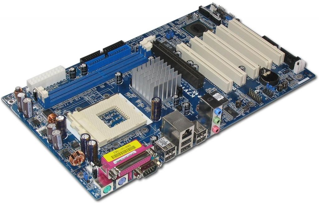 The UEFI (stands for the Unified Extensible Firmware Interface) is popularly known as a detailed interface between a working framework and a stage program.
UEFI is the primary code run by a computer when it is booted by planning the machine by testing it amid bootup and clears the way for the working framework to begin. It tests and initializes components such as the processor, optical drives, video cards, difficult drives, and USB drives.
Read more >> What Should You Know About CompTIA A+ Troubleshooting Model?
In the event that any blunders happen, the BIOS/UEFI reports them as the portion of the testing organization, also popularly known as the POST (stands for the power-on self-test). To get to the BIOS, press the key or key combination shown on the screen when the framework begins booting to get to the BIOS program menu.
UEFI, which may be a GUI or text-based menu, supplanted the bequest BIOS firmware interface in most PCs, with most UEFI firmware usage giving bolster for bequest BIOS administrations. UEFI can bolster further diagnostics and repair of computers, indeed with no working framework introduced. All Mac computers utilize UEFI firmware.
Pros of UEFI:
- Bolster for difficult drives of 2TB and higher capacity. These drives require the utilization of the GPT (stands for the GUID Partition Table) to get to full capacity.
- Faster framework startup and other optimizations.
- Larger-size ROM chips utilized by UEFI make room for extra highlights, way better diagnostics, the capacity to open a shell environment for simple streak upgrades, and the capacity to spare numerous BIOS arrangements for reuse.
Firmware Updates
Common steps to find a streak BIOS overhaul and introduce it: Go to the vendor’s site and seek for “downloads” or “tech support” joins. The BIOS overhauls are recorded by framework show and by form; maintain a strategic distance from beta (prerelease) versions.
Locate the right BIOS upgrade for your framework or motherboard.
Determine the establishment media required to introduce the BIOS picture (Windows-based installer, bootable CD, or USB flash drive).
Download all records required to introduce the BIOS image.
Create bootable media and after that take after the vendor’s information to put the loader and BIOS picture records on the media.
Installation
- Bootable media: Make beyond any doubt the drive the primary thing within the BIOS boot arrangement. Embed or interface your media and restart the framework. In case provoked, press a key to begin the updated handle. After the method begins, it takes roughly three minutes to rewire the substance of the BIOS chip with the upgraded information.
- Windows: Near all Windows programs before the process of beginning the upgraded handle. Explore the envelope containing the BIOS overhaul and double-click it to begin the upgraded handle.
 Take after the prompts onscreen to total the method (takes around 3 minutes).
Evacuate the media and restart the framework to utilize your modern BIOS highlights. Reconfigure the BIOS settings in the event necessary.
Caution: Whereas performing a streak overhaul, make beyond any doubt you don’t turn off the control to your PC. Hold up for a message demonstrating that the BIOS overhaul has been completed before the process of touching the computer. In case the control goes out amid the streak upgrade, the BIOS chip may be rendered useless.
Security Features
Security highlights of different sorts are scattered around the normal framework BIOS/UEFI dialogs. Highlights and their areas change by the framework and might include:
- BIOS secret word: BIOS Settings Secret word or Security dialogs.
- Empower BIOS secret word to include allow get to BIOS setup dialogs.
- Power-on secret word: Designed through the Security discourse.
 Anticipates anybody without a secret word from the beginning of the system.
 - Chassis interruption: Different locations Boot segment assurance: Progressed BIOS Highlights dialog
- Note: BIOS watchword & Power-on secret word can be overcome by opening the framework & clearing the CMOS memory.
These mentioned features are able to support drive encryption:
- TPM (stands for the trusted stage module): Security discourse. Windows versions that bolster BitLocker FDE (full-disk encryption) highlight TPM to secure the substance of any indicated drive.
- LoJack for tablets: After-market item implanted in firmware or introduced by the end-user; not overseen with BIOS dialogs. Utilized for finding lost/stolen laptops.
- Secure Boot: Boot or other dialogs. Square’s establishment of other working frameworks & requires the client to get to UEFI setup by restarting the computer in an extraordinary investigating mode inside Windows 8 or afterward.

Interface Configurations
Interface arrangements comprise:
- SATA arrangements alternatives: To enable/disable SATA & eSATA ports & to arrange SATA have connectors to run incongruent, local, or Attack modes.
- USB has connectors & charging back: Utilized to empower USB 2.0 & 3.0 in your framework BIOS so that all your system’s USB ports will run at legitimate speeds.
- Audio & other types of Ethernet ports: Utilized for the purpose of designing sound and other coordinate ports.
CMOS Battery
The CMOS (which stands for the complementary metal-oxide-semiconductor) battery keeps up the time, date, difficult disk, and other setup settings within the CMOS memory. CMOS batteries are little and are joined specifically to the motherboard. The CMOS battery gives control to preserve the substance of the CMOS chip.
Battery life is a few years, but a moo CMOS battery can cause issues with drivers and now and then booting. Framework date & time mistakes can be a sign that it is time to check or alter the battery. To clear CMOS on most frameworks, put a jumper piece over two jumper pins. A few frameworks highlight a port-cluster-mounted thrust button to clear the CMOS.
Read more >> CompTIA A+ Port Numbers: Important Things to Know in 2022
CPU Features
CPU Cores: Single Core and Multicore
A single-center could be a chip with one CPU (handling unit) that gets information from the computer program to perform calculations for yield. Multicore processors are computer processors that coordinate circuits with 2 or more isolated handling units which study and execute program information as if the computer had a few processors. The good thing about a multicore processor versus having numerous physical processors may be a lessening in cost and they work with any working framework that bolsters conventional single-core processors.
Virtualization
CPU virtualization emphasizes execution and runs straightforwardly on the processor at whatever point conceivable. The fundamental physical assets are utilized at whatever point conceivable and the virtualization layer runs enlightening as required to create virtual machines work as in the event that they were running specifically on a physical machine. Most current processors highlight virtualization back, moreover known as hardware-assisted virtualization. Hardware-assisted virtualization empowers virtualized working frameworks and applications to run quicker and utilize fewer framework assets.
Hyperthreading
Hyperthreading is Intel’s exclusive concurrent multithreading usage utilized to progress the parallelization of computations (doing different assignments at once) performed on an x86 chip. When hyperthreading is empowered within the framework BIOS and the processor is running a multithreaded application, the processor is imitating 2 physical processors.
CPU Speeds
A mode of transport may be a circuit that interfaces one portion of the motherboard to distinctive components such as the CPU, memory, chipsets, development spaces, capacity interfacing, and I/O ports. The more information a transport can handle at one time, the speedier it permits data to travel. The speed of the transport, measured in MHz, alludes to how much information can move over the transport simultaneously.
Overclocking
In computing, the reason for overclocking is to extend the working speed of a given component. In present-day frameworks, the target of overclocking is expanding the execution of a major chip or subsystem, such as the processor or design controller, but other components, such as framework memory (Smash) or framework buses are commonly included. The trade-offs are expanded control utilization (warm), fan commotion (cooling), and abbreviated life expectancy for the focused on components.
Most components are outlined with an edge of security to bargain with working conditions outside of a manufacturer’s control. Overclocking methods in common point to exchange this security edge by setting the gadget to run at the higher conclusion of the edge, with the understanding that temperature and voltage must be more entirely observed and controlled by the client.
Integrated Graphics Processing Unit
An IGP (stands for the integrated graphics processing) unit could be an illustration chip that coordinates into a computer’s motherboard. The IGP serves the same reason as a video card, which is to prepare the design shown on the computer. IGP takes the design parcel of the preparing stack off the most CPU.
Due to IGPs being fastened onto the motherboard, their measure is constrained and they cannot use a devoted fan to cool them as a few video cards do. Usually, the main reason why IGPs ordinarily don’t have the same execution as video cards is that they are joined to the computer’s PCI or AGP ports. IGPs due to their little estimate are great arrangements for tablet computers and entry-level desktop PCs.
Processor Compatibility
AMD & Intel are the 2 primary companies creating CPUs. AMD processors utilize the PGA shape figure where the contact pins that embed into the attachment are mounted to the CPU itself. Intel processors utilize the LGA shape figure where the pins that interface the CPU to the motherboard are mounted on the motherboard’s attachment. How the CPUs physically join and how they work inside imply that the two brands are not congruous with one another. Free producers of motherboards, such as ASUS and ASRock, make a few distinctive sheets that back CPUs from both companies.
Read more >> CompTIA A+ Linux Commands | The Complete Guide in 2022
Cooling Mechanisms
Computer cooling is required to expel the squander warmth delivered by computer components and to keep components inside allowable working temperature limits. Components that are helpless to brief glitch or changeless disappointment in case overheated incorporate coordinated circuits such as CPUs, chipsets, design cards, and difficult disk drives.
The essential prerequisites for legitimate CPU cooling incorporate the utilization of a fitting warm sink (which incorporates a fan) and the application of a suitable warm fabric (oil, glue, or a pre-applied warm or phase-change compound). Progressed frameworks some of the time utilize fluid cooling instead.
Expansion Cards
An expansion card is often known as an electronic card that’s utilized to include additional usefulness to a computer. It is embedded into an extension space on the motherboard of a computer. Development cards contain edge connectors that are utilized to form an electronic connection between the motherboard and card, in this way empowering these 2 to communicate.
Video Cards
A video card is an extension card that produces nourishment of yield pictures to a show gadget (such as a computer screen). Most video cards are not restricted to basic show yield. Their coordinated design processor can perform extra preparation, evacuating this assignment from the central processor of the computer. Video cards can come as onboard or as add-on cards.
Sound Cards
A sound card is a card for a coordinate circuit for creating sound on a computer that can be listened to through speakers or earphones. In spite of the fact that the computer doesn’t require a sound card, it’s included on each machine either in an opening or the motherboard.
Above is all information associated with the CompTIA A+ motherboard diagram, which can be beneficial for your process of acing the CompTIA A+ certification exam as well as in your career path as an IT professor.
Motherboard Schematic Diagram — tokzamer.ru
The most common type of desktop memory currently available is DDR numbered 2, 3 and 4.
Where is the best place to buy a motherboard?
More on the topic: Cable laying in a trench
Motherboard: what, why and why?
The scheme posted in the article makes it possible to understand that some devices are launched along with them and their basic parameters are being established.
Actually, as you already understood, this article is devoted to the latter.
In this case, each voltage channel must be provided with the corresponding required current consumption. The motherboard, elementarily, should fit into your system unit. All other components of the motherboard can be conditionally divided into groups: Various ports for connecting both internal devices, processor socket, RAM slots, video card slots, and external ones — hard drives, optical drives, USB drives.
So, on modern devices there are about half a dozen connectors for various devices, except for those that will be discussed in the article. FPanel system panel connectors or front panel connectors. South, respectively, below in the south of the PCI bus and does without cooling.
Chipset Also called a chipset. If the voltage does not change, then we connected the resistor to the wrong place and everything needs to be carefully rechecked. Diagnostics of a faulty motherboard using a multimeter showed the presence of all supply voltages except for terminating VTT. Capacitors are needed to equalize voltage or block current in a circuit.
For example, the northbridge is not simply called that, but precisely because of its position relative to the center of the motherboard. And here’s what: a power supply button and restarting the computer, a hard disk load indicator, a built-in squeaker speaker.
The resistor we need is connected to the output of the operational amplifier of legs 1 and 7. Thanks to them, the main parameters that this device owns are determined. In addition, the described design with passive coolers, an analogue of which is actively used, by the way, in silent models of video adapters from the same manufacturer, reduces acoustic noise from the motherboard as well.
What is a motherboard
Used in older boards, the linear voltage regulator was a microcircuit that lowered voltage by dissipating excess voltage as heat. For example, the north bridge is far from just called that, namely because of its position relative to the center of the motherboard.
What actually connects there? Motherboard Form Factors When choosing a motherboard, you need to keep in mind such a parameter as the form factor.
More often than not, it is the south bridge that fails, taking all the blows first in the so-called PWM controller, which controls the mosfet transistors through driver microcircuits. Intel Processor Power Line Specifications When repairing computers, I often have to diagnose a motherboard malfunction.
Diagnostics of the motherboard on this is considered complete and further repair consists in replacing faulty components with new ones. This is what a microchip looks like on a printed circuit board. And taking into account their number in the processor multiplied by the switching frequency, a very large total current consumption of the processor is formed.
The choice of the correct socket depends not only on the manufacturer — Intel or AMD, but also on the line of which the particular processor belongs. To improve the power supply of motherboards, Intel has created a new ATX12V power supply specification. When installing a processor that consumes a lot of power into the motherboard, the regulator, and with it the motherboard, could fail due to overheating.
You can recognize the switching voltage regulator on the board by the inductors. Connector for connecting floppy disks Quite rare, but still just a miracle, some kind of motherboard component found in our time. In addition, a cooler is usually placed on the processor, which also has its own separate heatsink that effectively removes heat. Of course, the computer does not scatter space, but there this problem is not so acute. A power supply with a pin header can be used on a motherboard with a pin header, leaving the four extra pins unconnected.
The scheme of this device is very complex, and it itself includes several components. I can say that repairing motherboards is not always cost-effective, but in the event of a processor power circuit failure, for example, it is quite feasible. This allows you to get high overclocking results and increase the life of the equipment.
PC Motherboard Schematics Gigabyte, Foxconn, ECS, Asus, Intel
PC Motherboard Schematics
PC Motherboard Schematic Asus P5BW-MB
download
PC Motherboard Schematics ECS 321-1-4-02
download
PC Motherboard Schematics ECS 331-1-4-02
download
PC motherboard schematics ECS 400-1-4-02
download
PC Motherboard Schematics ECS 558-1-4-02
download
PC Motherboard Schematics ECS 845GV-M2 — REV 1.2A pc
download
PC Motherboard Schematics ECS 865G-M8
download
PC Motherboard Schematics ECS 945GCT-M — REV pc
download
PC Motherboard Schematics ECS 945G-M4
download
PC Motherboard Schematics ECS 945PL-A
download
PC Motherboard Schematics ECS 946GZT-AM
download
PC Motherboard Schematics ECS A33G
download
PC Motherboard Schematics ECS A535-1-4-02
download
PC Motherboard Schematics ECS A901-1-4-02
download
PC Motherboard Schematics ECS A928-1-4-02
download
PC Motherboard Schematics ECS A980-1-4-02
download
PC Motherboard Schematics ECS C51PVGM-M
download
PC Motherboard Schematics ECS C51-M941
download
PC Motherboard Schematics ECS G332-1-4-02
download
PC Motherboard Schematics ECS GeForce6100SM-M3
download
PC Motherboard Schematics ECS I4XIXX — REV 0. 3
3
download
PC Motherboard Schematics ECS P4M800PRO-M
download
PC Motherboard Schematics ECS P4M890T-M
download
PC Motherboard Schematics ECS P4M890T-M3
download
PC Motherboard Schematics ECS RS485M-M
download
PC Motherboard Schematics ESC 761GX-M754
download
PC Motherboard Schematics Foxconn 648FX7MF
download
PC Motherboard Schematics Foxconn 661M08
download
PC Motherboard Schematics Foxconn 741M01C
download
PC Motherboard Schematics Foxconn 748A01
download
PC Motherboard Schematics Foxconn 845GV_PE_GE REV B pc
download
PC Motherboard Schematics Foxconn 845M02-GV
download
PC Motherboard Schematics Foxconn 848P7MB
download
PC Motherboard Schematics Foxconn 915A02
download
Foxconn PM AMD PC Motherboard Schematics
download
PC Motherboard Schematics Foxconn W920 PVT
download
PC Motherboard Schematics Foxconn W930 h2& h4
download
PC Motherboard Schematics Gigabyte 8I845GE775-G
download
PC Motherboard Schematics Gigabyte 8I845GE-RZ
download
PC Motherboard Schematics Gigabyte 8I845GV
download
PC Motherboard Schematics Gigabyte 8I845PE pro
download
PC Motherboard Schematics Gigabyte 8I845PE-RZ
download
PC Motherboard Schematics Gigabyte 8I848E
download
PC Motherboard Schematics Gigabyte 8I848E-L
download
PC Motherboard Schematics Gigabyte 8I848P
download
PC Motherboard Schematics Gigabyte 8I848P-G
download
PC Motherboard Schematics Gigabyte G31M S2C
download
PC Motherboard Schematics Gigabyte GA-8GEM800
download
PC Motherboard Schematics Gigabyte GA-8i845G
download
PC Motherboard Schematics Gigabyte GA-8i845GVM-RZ
download
PC Motherboard Schematics Gigabyte GA-8i945AEF-AE PC
download
PC Motherboard Schematics Gigabyte GA-8i945AEF-RH-AE PC
download
PC Motherboard Schematics Gigabyte GA-8i945AE-AE PC
download
PC Motherboard Schematics Gigabyte GA-8i945EF-RH PC
download
PC Motherboard Schematics Gigabyte GA-8i945GMBX PC
download
PC Motherboard Schematics Gigabyte GA-8i945GME PC
download
PC Motherboard Schematics Gigabyte GA-8i945GMF PC
download
PC Motherboard Schematics Gigabyte GA-8i945GMH-RH PC
download
PC Motherboard Schematics Gigabyte GA-8i945G PC
download
PC Motherboard Schematics Gigabyte GA-8i945G-PRO PC
download
PC Motherboard Schematics Gigabyte GA-965GM-S2 PC
download
PC Motherboard Schematics Gigabyte GA-965P-DQ6 V1.