ATX, EPS, and 80 PLUS Specifications
ATX, EPS, And 80 PLUS Specifications
In PSUs, certain standards are widely accepted by almost all manufacturers. In the following sections, we are going to make a brief reference to three of the most recognized and up-to-date specifications: ATX, EPS and 80 PLUS.
ATX Specification
Advanced Technology Extended, known as ATX, is a motherboard form-factor specification developed by Intel in 1995. In general, it gives some guidelines on computer cases, motherboards and PSUs design. The first ATX specification was released in late 1995 and defined three types of power connectors:
- Four-pin Molex
- Four-pin FDD connector
- 20-pin Molex motherboard connector
This specification stated that most of a PSU’s power should be provided on the +5V and +3.3V rails. This is because in those early times, these two rails powered all electronic components, and +12V rails were used only for fans and motors of peripheral devices. This original ATX specification remained almost unchanged until the year 2000.
All Intel Power Supply Design Guides for Desktop Platform Form Factors use the Revision naming scheme. However, some of us and most companies use the ATX naming scheme. For example, ATX 2.31 is in essence Revision 1.1, while ATX 2.4 is Revision 1.31. More precisely, an Intel Power Supply Design Guide revision includes the ATX guidelines. These refer mostly to form factor matters like dimensions and PSU design, and in some cases they also include specific guidelines about the fan that should be used in a form factor. The rest of the revision refers to more important matters, which have to do with the PSU’s performance, efficiency, environmental safety, reliability and so on.
From the year 2000 to today, many revisions were released, with ATX 2.4 (Revision 1.31), released in April 2013, being the latest. The main difference between ATX 2.4 and the previous ATX version (Revision 1.30) is the minimum efficiency recommendations on the 5VSB rail, which actually became less tight.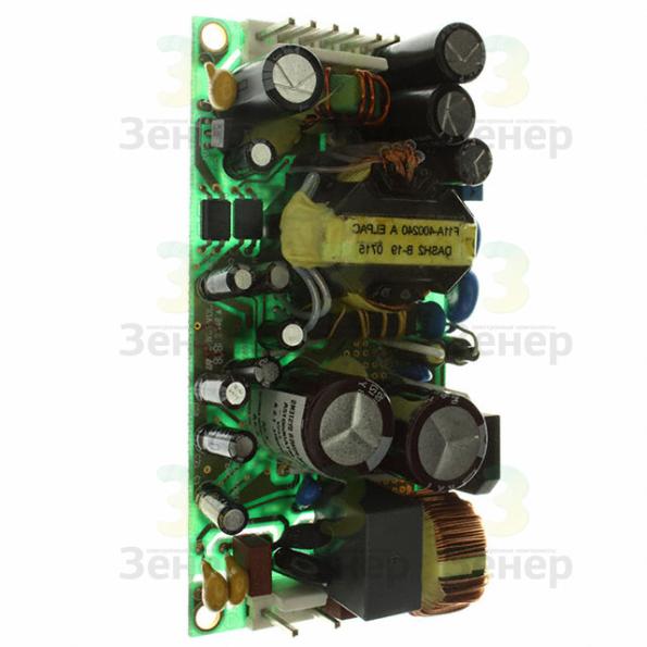 This is probably the first time that we saw a newer specification offering looser requirements, especially in an efficiency-related matter. While the rev. 1.30 spec recommended higher than 69 percent efficiency at 5VSB with 2.75W load on this rail, the newer spec recommends more than 55 percent efficiency with the same load. To be more exact, the rev. 1.30 spec took into account the requirements of the 2013 ErP Lot 6 and 2014 and 2016 ErP Lot 26 requirements directives, while the newer 1.31 follows the guidelines of the 2013 ErP Lot 6 and 2014 ErP Lot 3 directives, omitting the ErP Lot 26 directives. There is also a slight change in rise time. In the new ATX spec, the rise time waveform should be a straight line between 10 and 95 percent of its route, while in the previous specification, the range was 10 to 90 percent. A minimum loading condition for the second +12V rail was also added as a requirement, which in the 1.30 spec wasn’t required but only recommended. Finally, the CFX12V, LFX12V, ATX12V, SFX12V, TFX12V and Flex ATX guidelines were updated in ATX 2.
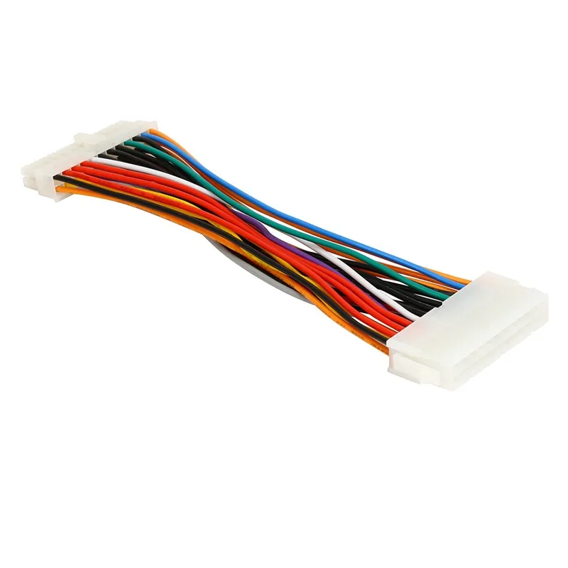 4.
4.
EPS Specification
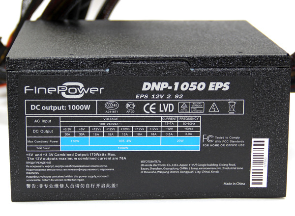
Entry-Level Power Supply Specification (EPS), which is a derivative of the ATX specification, was released for high-end PCs and entry-level servers. It was developed and released by the Server System Infrastructure forum. In order for a PSU to meet the EPS specification, it must have a 24-pin motherboard connector and an EPS (eight-pin) connector. It must also have one four-pin 12V connector if its capacity is 700 to 800W, or two four-pin 12V connectors for capacities of over 850W. The latest EPS specification is 2.92 (PDF available here).
80 PLUS Specification
80 PLUS represents an organization that certifies PSUs that have over 80 percent efficiency at 10, 20, 50 and 100 percent of their maximum rated load, and a power factor of 0.9 or greater at 100 percent load. For Bronze, Silver and Gold certifications, the power factor must be 0.9 or greater on all three load levels. Additionally, the newest Platinum level requires 0.95 or better power factor for servers.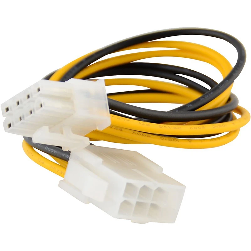
The first market-ready PSU was created in February 2005 by Seasonic. At first, the only certification level was 80 PLUS, but in the first quarter of 2008, the standards were revised, and Bronze, Silver and Gold efficiency-level certifications were added. The two latest efficiency level certifications, Platinum and Titanium, were added in 2010 and 2011, respectively. We look forward to seeing what the name of the next certification level will be, if there is one. The Titanium level is already pushing contemporary designs to their limits, and we believe that only with advanced, fully digital PSUs can efficiency levels go higher.
We must stress here that 80 PLUS initially certified non-redundant PSUs for desktop use at 115VAC, and 230VAC was used only for redundant PSUs (used in servers and data centers). This changed in April 2014, and 80 PLUS added certifications with 230V input. Since increased input voltage has a positive effect on efficiency (an increase of 1 to 1.5 percent compared to 115V), the 80 PLUS 230V requirements are stricter than the 115V ones.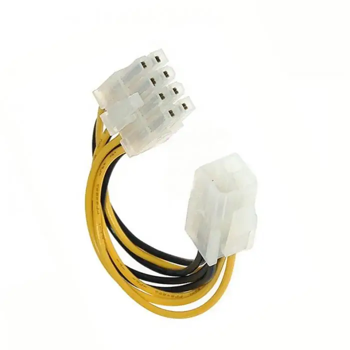 Below, you will find two tables listing all aforementioned efficiency certification levels.
Current page:
ATX, EPS, And 80 PLUS Specifications
Prev Page Monitoring Integrated Circuits
Next Page PSU Resources
Aris Mpitziopoulos is a Contributing Editor at Tom’s Hardware US, covering PSUs.
Topics
Power Supplies
PP12-EPS
- Power Supplies
* Supported PSU List
DA750 Gold
DA650 Gold
DA550 Gold
SX1000 Platinum
DA850 Gold
SX750 Platinum
DA1650 Gold
ET600-MG
ET500-MG
ET700-MG
Product Specifications
Model No.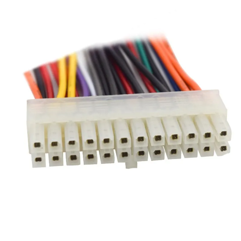
SST-PP12-EPS
Color
Black
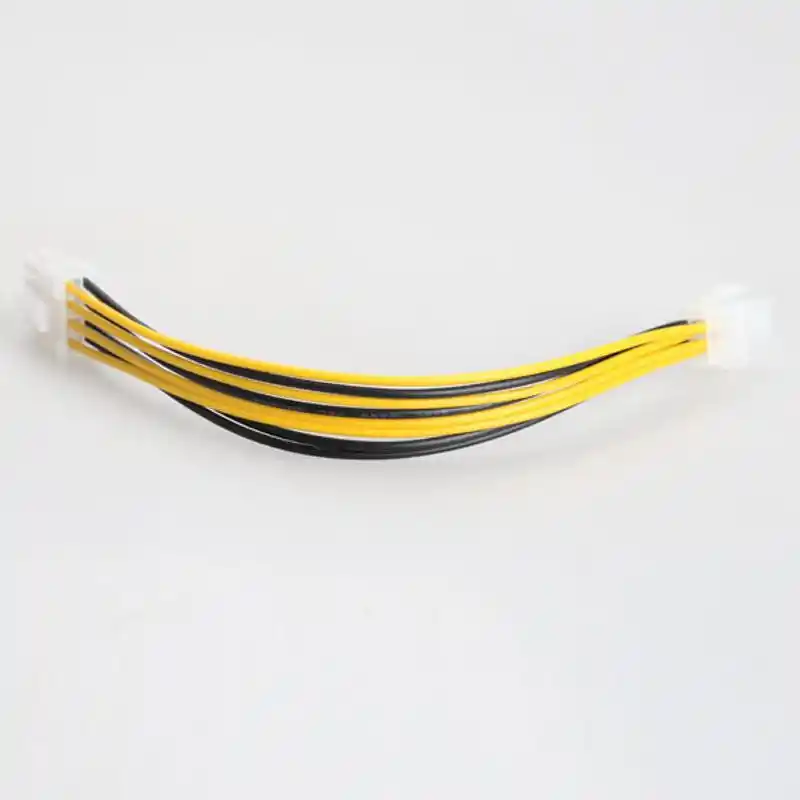
Connectors
2 x EPS 8 pin (PSU) to 1 x 12 pin (GPU)
Wire gauge
16 AWG
Dimension
550 mm (w/o connector)
File Download
| 描述 | Version | File Size | 下載 |
|---|---|---|---|
|
描述
|
Version
|
File Size
|
下載
|
|
描述
|
Version
|
File Size
|
下載
|
 47 MB
47 MB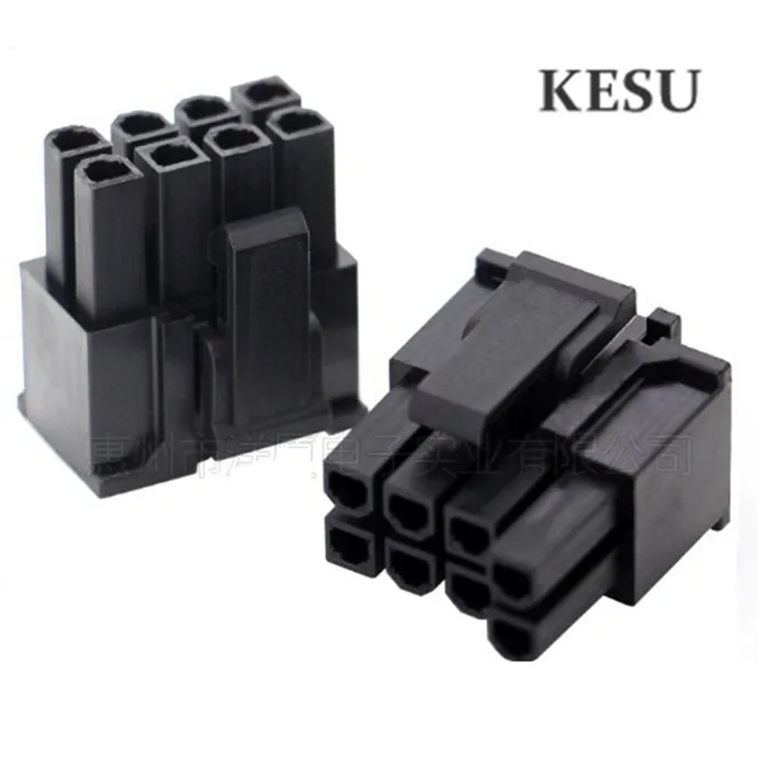 03 MB
03 MB
Recommended Products
View More
View More
View More
View More
View More
Product Reviews
Back to list page
MOD-ONE Custom Sleeved ASUS Power Supply Cable, 8-pin EPS
The MOD-ONE custom sleeved ASUS/ROG® 8-pin EPS power supply cable provides power from your ASUS/ROG® PSU to your motherboard’s 8-pin power connection.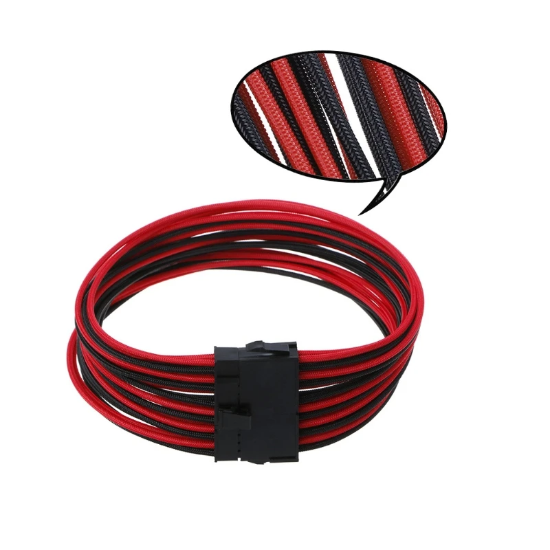
It all starts with premium wire
MOD-ONE premium wire is custom made to our exact specifications as a professional PC cable sleever and manufacturer. It is 100% free from unwanted markings and other text which can bleed through on some light sleeve colors.
Thicker is better. The 2.4mm outside wire diameter 16awg and 2.3mm outside wire diameter on 18awg gives MOD-ONE custom cables a more robust look compared to other manufactures. MOD-ONE premium wire is designed for a superior cable training experience due to its construction, rigidity and form holding ability.
Molex ATX Terminals for superior crimps
When it comes to executing the perfect crimp, you just can’t beat Molex brand terminals. Not only did they create the original ATX terminal (Mini Fit Jr series), but they are one of the biggest and most trusted names in wire harness manufacturing. All MOD-ONE custom MDPC-X sleeved PC power supply cables and extensions use Molex branded ATX terminals.
Each custom sleeved cable also uses our quality MOD-ONE connectors which are available in black or white. MOD-ONE connectors are also compatible with the Molex brand terminal extractor tool as well as the aftermarket versions.
Uniform wire lengths and in-line crimps
One of the most critical factors, and most unknown, in making the perfect custom sleeved pc cable is in perfectly cut and crimped wires. Wires within a cable that consist of unequal lengths will create bunching and twisting in the cable. Crimps that are out of alignment from each other and do not coincide with the natural curve of the wire can also create unwanted twisting.
We use precision machinery and skilled craftsman to ensure wires within a cable are the same length throughout, and have crimps that are in line with each other that work with the natural curve in the wire.
THE Legendary MDPC-X PC Cable Sleeving
MDPC-X is the first PET cable sleeving manufacturer to specifically cater to the PC enthusiast and PC modding communities.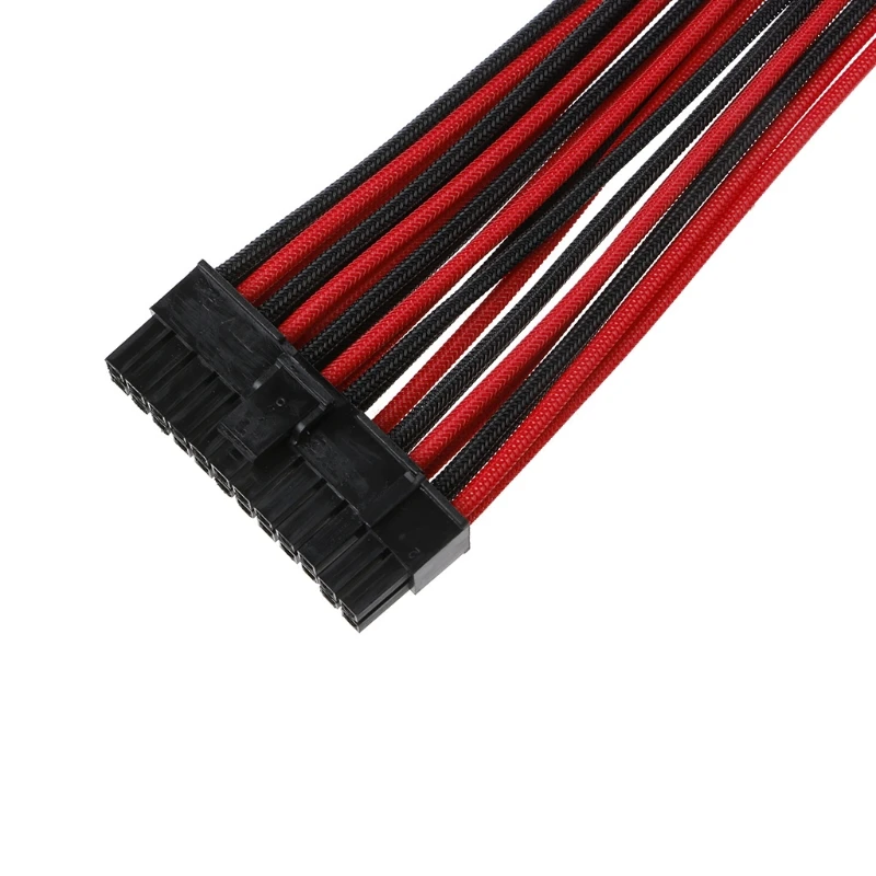 Before MDPC-X, cable sleeving was designed more for industrial applications were colors and weave density were not nearly as critical as it is in today’s custom PC cables. MDPC-X created a tighter weave without losing expandability, developed colors with greater opacity and vibrancy, and finally added UV lighting reactions that are sure to impress.
MDPC-X is a PET (polyethylene terephthalate) based cable sleeving. When it comes to custom sleeved PC cables, PET cable sleeving is a superior option over fabric-based materials like paracord. PET cable sleeving is more dust resistant and will not fray like fabric based materials can.
With over 50 cable sleeving colors and growing, the MDPC-X color pallet is sure to work with any custom PC style or theme.
Unprecedented UV Reactions
Before there was RGB, there was UV. MDPC-X strives to create the most intense UV reactive cable sleeving available. UV reactive cable sleeving makes for an impressive display of color.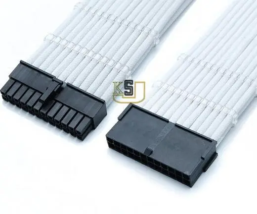
Melted sleeve ends, not crimped
Premium MOD-ONE Custom PC Cables have sleeve ends which are melted over the terminal as opposed to crimped under the terminal. To crimp terminals over the cable sleeving, more of the wire insulation is removed and the sleeve is crimped directly over the bare wire where the insulation used to be. By doing this, the crimp quality is reduced as the strain relief of the terminal is no longer crimped on the firm PVC insulation. By melting the cable sleeving end, the crimp is of the same quality as the stock power supply cables.
Premium MOD-ONE Cable Combs
MOD-ONE Cable Combs are laser cut in-house from quality 3/16” thick acrylic. These combs have been specifically designed for use with MOD-ONE Premium PSU Wire and MDPC-X Cable Sleeving to ensure a snug fit for the best possible cable management experience.
Custom Cable Pin-Outs
Factory power supply cables are not designed with sleeved wires in mind. Because of this, many of the individual wires within a factory cable cross over each other. The cable is then sleeved with a single large piece of sleeving, or the wires are bound together with no sleeving. If these cables were to be taken apart, sleeved, and then put back in the same way, the cable would have a large bulge in the center were all of the wires cross over each other. To solve this, we custom route the wires to matching receptacles and create a custom pin-out to better designed to worked with individually sleeved wires. Not only will this create cleaner cable runs, but we also test every cable we make with a power supply testing tool to ensure continuity.
Proudly Made in the USA
Each MOD-ONE custom sleeved cable is made right here in the USA just for you! We take pride in every cable we make and test each one before it ships. Our cables are not only designed to look good, but to also last through multiple PC teardowns and rebuilds. Order a set and see the difference!
Electrophoresis Power Supplies – EPS
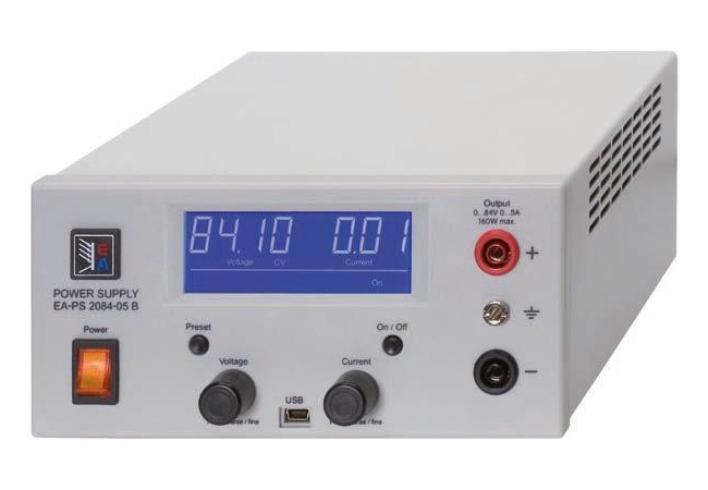
The Power Supply is designed for electrophoresis and blotting techniques including large format and high throughput applications. The small footprint, large handle, and simple operation make the Power supply easy to set up and use in your lab. With the large, easy to read LED & LCD, simply set the constant parameter, set the timer (if desired), and push start.
Sleek Model
Features
- Compact and Light weight
- Overload / short – circuit protection
- Suitable For Mini Agarose, SDS – PAGE, Paper, Immuno electrophoresis and blotting systems
Technical Specifications & Ordering Information
| Model | EPS/PS/ SLK 100 | EPS/PS SLK 200 | EPS/PS SLK 300 | EPS/PS SLK D100 | EPS/PS SLK D200 | EPS/PS SLK D300 |
|---|---|---|---|---|---|---|
| DC Voltage | ||||||
| Current | 100mA | 200mA | 300mA | 100mA | 200mA | 300mA |
| Control | ||||||
No.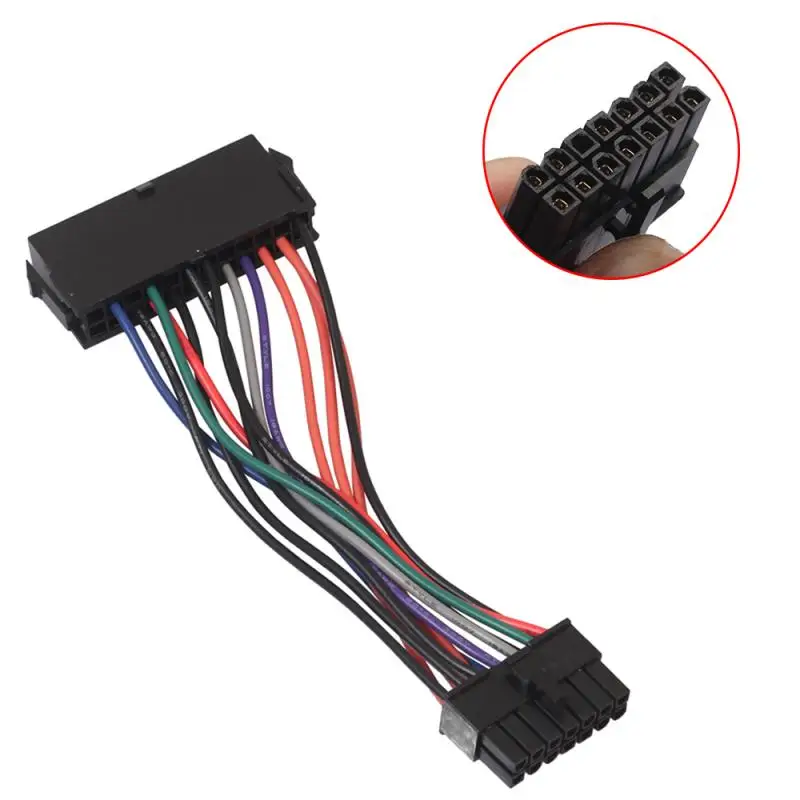 of Output of Output |
||||||
| Power | ||||||
Sinusoidal Model
Features
- Compact and Light weight
- Seven segment display and Digital control
- Easy to use: Knob and membrane key
- Buzzer and real time process
- Overload / short – circuit protection
- Suitable For Agarose, SDS – PAGE, Paper, Immuno electrophoresis and blotting systems
Technical Specifications & Ordering Information
| Model | EPS/PS Sino 300/100 | EPS/PS Sino 300/200 | EPS/PS Sino 300/300 | EPS/PS Sino 500/500 | EPS/PS Sino 500/1000 |
|---|---|---|---|---|---|
| DC Voltage | 0 to 300V | 0 TO 300V | 0 to 300V | 0 to 500V | 0 to 500V |
| Current | 0 to100mA | 0 to200mA | 0 to300mA | O to500 | O to1A |
| Timer | 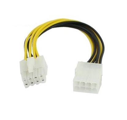 59 Min 59 Min |
||||
| Display | |||||
| Resolution | |||||
| Parameters | |||||
| Working temperature | |||||
| Relative Humidity | |||||
| Power | |||||
| Output | |||||
| Control | |||||
Liquid Crystal Display- Model
Features
- Variable LCD model with a maximum 1000 mA with safety
- Constant Voltage and constant current modes with auto balancing facility
- Programmable for 20 users depends on their applications
- Fine adjusting facility for setting the parameters
- Over load and short circuit protection
- Weight is around 2 kg made up of Injection molding ABS plastic enclosure.
- Buzzer and memory option.
- Auto restart set program in case of power failure.
- Programmable 20 mode power supply
- Timer (999 min)
- Four output terminals
- User Guide
Technical Specifications & Ordering Information
| Model | EPS/PS LCD 300/200 | EPS/PS LCD 300/300 | EPS/PS LCD 500/500 | EPS/PS LCD 500/1000 |
|---|---|---|---|---|
| DC Voltage | 0 to 300V | 0 to 300V | 0 to 500V | 0 to 500V |
| Current | 0 to 200 mA | 0 to 300 mA | 0 to500 mA | 0 to1A |
| Timer | ||||
| Display | ||||
| Resolution | ||||
| Parameters | ||||
| Memory Option | ||||
| Parameter Control | ||||
| Working temperature | ||||
| Relative Humidity | ||||
| Power | ||||
| Output | ||||
| Weight | ||||
EPS: Electrical Power Supply — ECE3SAT
In a clean room at Astrotech, the solar panels of the Dawn spacecraft are extended to their full extent — From https://commons. wikimedia.org/wiki/File:Dawn_solar_panel.jpg
Electrical Power Supply (EPS)
The Electrical Power Supply, or EPS of the CubeSat is composed by
three modules which are the PCC (Power Control Circuit), the PV
(photovoltaic panel) and the BAT (Battery). The role of the EPS is
to generate, store and distribute the electricity produced by the solar
panels.
Subsystems of EPS
PCC is responsible for the voltage regulation, the modules
protection and the energy distribution. In others words, it has to
manage the energy through the ECE3Sat. It communicates with the
OBC, thanks to a microcontroller.
The PV has to generate the electricity using the sunlight and the
photovoltaic effect. This will be possible thanks to five solar panels,
on each side of the CubeSat.
The BAT module has to store this energy to enable its using at any
time.
EPS Subsystems
The goal of the state of the art is to establish an inventory of the
existing technologies and to see their underlying potential of their
utilization in the project.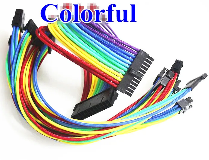
PV
The solar cells generate electricity by absorbing sunlight thanks to the
photovoltaic effect.
In space at Low Earth Orbit, the sunlight is not filtered by the
atmosphere. The efficiency of a solar panel depends of the wavelength of
the photons that it can absorb. Therefore, in a space context with a
larger wavelength of photons available than at Earth, the technology
used for the solar cells has to be able to absorb the maximum amount of
photons. More, since the area available of the solar panel is strongly
limited on the CubeSat (each side size 100 cm², and has to integrate
solar cells but also sensors and wires). The triple junction technology
solar cells have a layer well adapt to a large wavelength area with an
absorption wavelength from 300 nm to 1700 nm. This option but also other
types of technology have been study in the State of the Art document.
Wavelength absorption depending on the layer material
BAT
The energy produced by PV panels has to be stored partially to deal with
the eclipse period in which there is no more sunlight, and so no more
electricity production.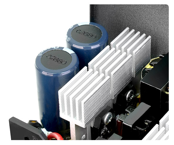
Batteries are generally the preferred method of energy storage for
CubeSats. There are several factors to consider when choosing the
dimensions and technology.
-
The nominal voltage has to be line with the buses voltage required
by the modules supplied by the battery. -
The energy density determines the size of the battery compared to
the needed energy -
The maximum discharging current limits the maximum number of modules
running at the same time. This also limits the maximum consumption
of any single module. -
The self-discharge will affect the battery capacity, so it must be
taken into account when deciding the total capacity. -
The charging time of the battery minus the oversize part cannot be
longer than the sunshine time, or else it will be a lack of
electricity during the eclipse. -
The thermal charging and discharging range are linked to the spacial
conditions, and must be line with the thermal regulation modules to
provide optimal or minimal operating conditions -
The maximum number of cycles depends on the length of the
space mission.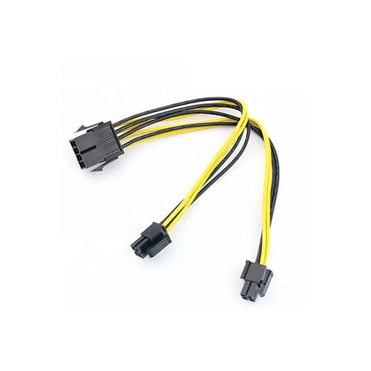 As the capacity of the battery diminishes over time,
one can choose to over-size the battery or to choose a type which
has a higher number of maximum cycles.
Many kinds of 1U batteries already exist. The power stored in each of
these batteries is about 10 to 30 Wh.
The ECE3SAT team considered different type of battery technology,
including chemical batteries. The maximum energy density and watt-hour
per kilogram rate with a correct price are the Lithium batteries (in the
chemical battery technology). This technology is usually the one which
is used in CubeSats.
The lithium batteries (Li) can be divided in two categories. Lithium
Polymer or Li-Po, and Lithium Ion or Li-Ion. These two categories have
both advantages and disadvantages comparing with the other.
Lithium Polymer
- Strengths:
- Can have different tiny forms
- Low weight
- Safest batteries
- Weaknesses:
- Less Energy saving than Li-Ion batteries
- More expansive
- Regulated charge
Lithium Ion
- Strengths:
- Can have different tiny forms
- Low weight
- Highest power saving
- Weaknesses:
- Shortest life cycle than Lithium Polymer batteries
- Can cause bypass
PCC
When the electricity has been generated by the solar panels.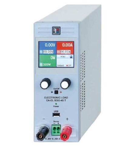 It has to
be manage by the PCC modules. The PCC has to distribute the electricity,
to the battery to store it or directly to the modules to use it. PCC has
also to protect modules against over-current and reverse-current. To do
so, a microcontroller, several MPPT modules and regulators will be
integrate in the circuits.
Microcontroller has to fit with the need of communication with the OBC
thanks the I2C buses, of electricity distribution control with digital
outputs for the electronic switchs and of measure of battery level of
charge using sensors.
Architecture
There is two main architectures for CubeSats which are centralized and
distributed. Each one has several advantages and disadvantages.
According to a survey on 25 CubeSats led by university or affiliated
university whose purpose was to determine what type of architecture was
implemented, 80% of the CubeSats used centralized architecture while 20%
used distributed architecture.
References
- Utah State University
- Universiti Tunku Abdul
Rahman - The CubeSat Cook
Book - Characterization of Lithium-Polymer batteries for CubeSat applications,
Nimal Navarathinam, Regina Lee, Hugh
Chesser - Techbrief
System Specifications EPS
The system specifications of EPS are mainly focus on the losses of the
PCC, and its weight which shall be between 20-30% of the total weight of
the CubeSat.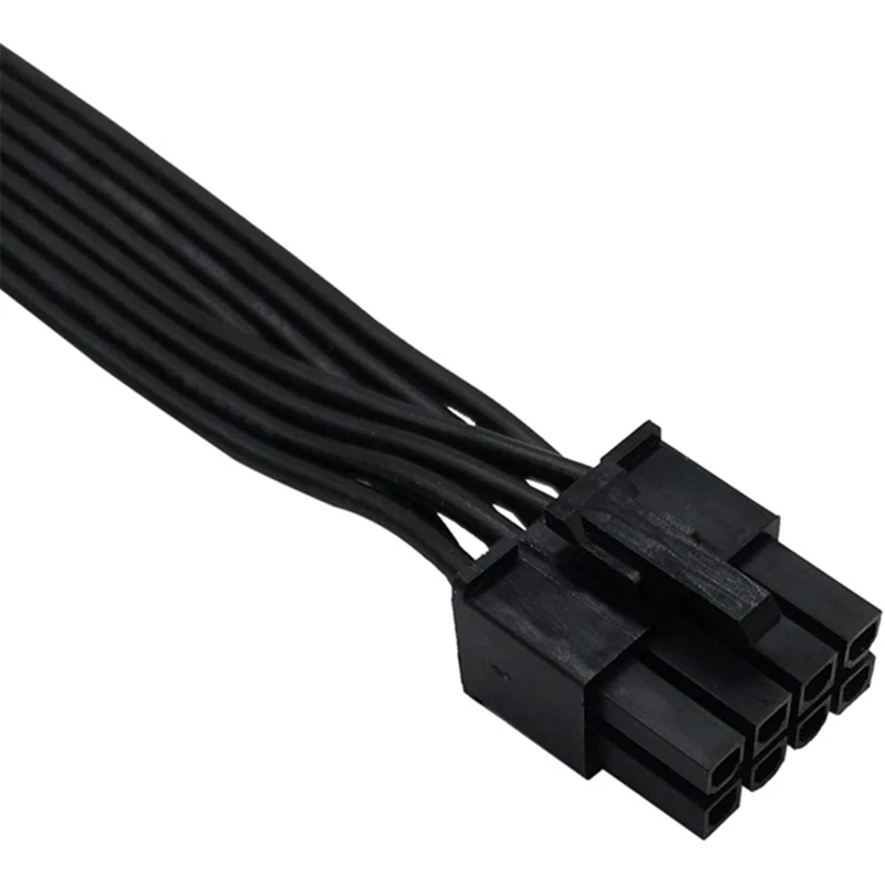
BAT (Battery)
In these system requirements, two batteries will be considered. A
primary battery, which will be named the battery and secondary battery
which will be named the cell.
Thus, many factors have to be taken in account such as: the battery’s
temperature, the number of cycles of the battery, the charge level, the
charging time, the battery’s capacity and the heater’s consumption.
Battery
PV (Photovoltaic panels)
The primary function of the PV module is to provide energy to the
battery and the other modules. But other systems specifications shall be
taken into account, which are: the MPPT’s (Maximum Power Point Tracker)
wiring, the technology and the size of solar panels (Triple Junction),
the protection against certain wavelength, the wiring of solar panels,
and the decrease of the efficiency of solar panels.
Solar panel
PCC (Power Control Circuit)
The role of the PCC is to manage and distribute the energy through the
entire CubeSat thanks to a microcontroller. This energy control shall
take into account: the regulators (3.7V, 5V) the electronic switches,
the battery charge level and the communication with the On Board
Computer (OBC).
Microcontroller
SystemSpecifications EPS
Sizing EPS
BAT
The battery will be a Li-Po and will have a voltage of 3.7 V. 2.25 Wh is
needed by the CubeSat, and the step of charge of the battery must be
between 20% and 90%. Therefore, the battery must deliver 3.21 Wh. There
will be an electric heater to maintain the temperature of the battery
between 0°C and 5°C. This is to avoid the depth of discharge without
consume a lot of energy.
PV
5 PV Triple junction panels are used to produce the electricity using
Sunlight. Since the satellite is a Cube, only one to three panels can be
under sunlight at the same time. Their efficiency is usually between 24%
and 30%. The energy generated depends on the area of PV under sunlight,
the inclination of the CubeSat and the solar intensity. Following Matlab
simulations, the best inclination has been computed:
CubeSat angles
The maximum value of power is obtained for three sides under sunlight
with ϕ = 45° and v = 55°
Solar Cells are connected in series but every section will be in
parallel: every solar panels will be connected to each other in
parallel.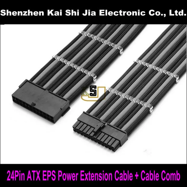
PCC
A MPPT is used to obtain the better power as possible. The Solar Panels
will deliver a voltage until 4V. So, the MPPT have to handle a maximum
input voltage of 4V and deliver a voltage of maximum 3.7V. Regulators
are used to provide the different parts of CubeSat with 3.3V and 5V.
A microcontroller has to control the energy distribution in the entire
CubeSat. So, it needs four digital/analog outputs to the other modules
and two to the battery: One connection to provide the microcontroller
and an other to send the step of charge. An UART communication is used
between the EPS and the OBC. An SPI communication is used for the other
connections.
Files
- Batteries
- PCC
- Microcontrollers
Feasibility Study EPS
The feasibility study aims to assess the practicality of the EPS module.
The purpose of this stage is to assess the performance according to the
association of the requirements and the state of the art.
PCC
As a brief remind, the PCC module is responsible for the distribution
and regulation of electricity through the CubeSat. There is many
requirements to fit such as the protection of the modules, the
communication with the OBC and the energy distribution from PV cells to
battery for the storage and/or to module for the consumption.
The MPPT will have to handle a maximum input voltage of 4V from solar
panels and supply power to a 3.7 V battery. Redirecting the current to
regulators providing energy to the modules (3.3V and 5V). The modules
are both connected to the panels and the battery, that is why regulators
will be connected in parallel to the MPPT output and the battery. An
additional cell has been integrated because of the large amount of
energy needed for the detumbling phase, the battery will not be enough
to ensure the power supply in this time.
It has been established that a 3.3V regulated bus detumbling could be
used to supply ADCS and OBC (which are on the same board), the other 5V
converters will be connected to TCS and EDT. These figures are for now
only indicative and will have to be changed according to the needs of
each module.
The MCU is used for gathering and computing the housekeeping data,
taking decisions for connecting/disconnecting users in case of failure
and communicating with OBC thanks to an UART bus. The battery level of
charge is harvested through an analog-digital converter.
A schematic of the description above, develops the architecture more
clearly:
Electrical schematic
According to the availability on the market, the type of regulators
varies as a function of the input and the output. As the battery charge
regulator receives a various input from MPPT which can be superior or
inferior to 3.7V, it has to work as a step-up and step-down regulator.
For increasing the voltage from 3.7V to 5V the second regulator should
be a step-up. As the last regulator decreases the voltage to 3.3V, it
should be a step-down regulator. But, since the battery’s output voltage
decrease with its level of charge, the input voltage of regulators could
be under 3.3V. Therefore, the last regulator should not be only a
step-down regulator, it has to be a step-up/step-down voltage regulator,
with a 3.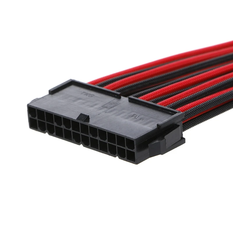 3V output.
Microcontroller
The microcontroller has to handle the energy distribution of the entire
CubeSat, and has to communicate with the OBC too. Thus, it needs four
digital/analog outputs (EDT, ADCS, Telecom, OBC), one BUS with a two-way
communication between the microcontroller and the OBC in: UART. And two
inputs with a power BUS and one another BUS which is used to send data
of the battery level of charge to the microcontroller: SPI.
Energy consumption
Generally, microcontrollers consume few energy, around the mirco ampere
for the “Active mode” and around the hundreds of nano ampere for the
“Off mode”. Others microcontrollers are more economical, they can be
used with six different ways.
Voltage range
The voltage range of the microcontroller depends of the output voltage
of the battery, which is 3.7V.
Almost microcontrollers have a voltage range of 2-3.6V, except for the
ATMEGA1281 which has a voltage range of 2.7-5.5V.
Memory
In the light of the functions of the microcontrollers the memory didn’t
have to be huge.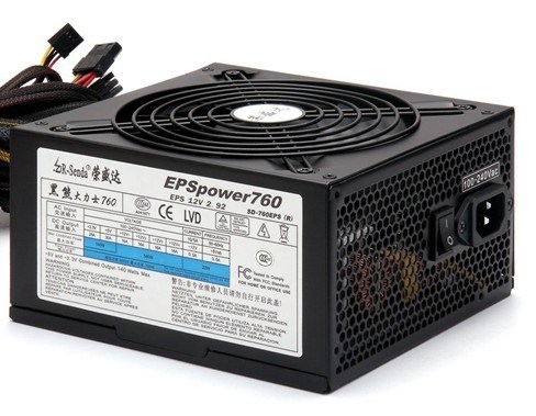 All the microcontrollers are viable.
PV
The sizing of this module has to be accurate and margins have to be
considered to be sure of the capability of production compare to the
consumption.
The energy production of the PV mainly depends of two factors which are
the efficiency and the surface area of the cells. Other characteristics
such as temperature, way to wire or weight have to be taken into
account.
Temperature
The PVs are subject to high electro magnetic radiation that cause huge
variation of the temperature over time. (Around 100°C of difference
between solar exposition phasis and eclipse). Then PVs shall be sized to
undergo the extreme conditions of space environment.
Surface & Efficiency
The limited surface area on each side of the nanosatellite implies some
restriction on the type of PVs available on the market and in compliance
with the need of production. Efficiency and surface being related to
each other, finding a compromise between them could imply an increase in
the cost.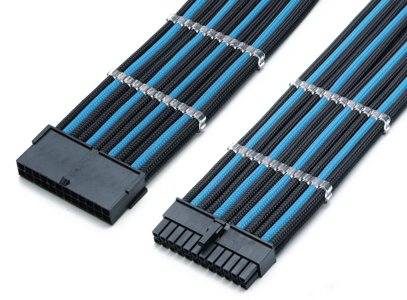
As panel’s efficiency decreases over time, the capacity of production
shall be computed for the beginning and the end of life. According to
the allocated power budget, efficiency shall be maximized, Triple
Junction solar cells are well indicated for this last condition.
Generally, the solar cells designed for 1U CubeSat are between 25% and
30%.
Triple junction solar cells are used in space, our CubeSat will
integrate this technology too. To save money, a choice of solar cells
rather than complete solar panel has been studied.
The advantages of this solution are the flexibility on architecture, the
cheaper cost, and the number of choices between different TJ solar cells
The disadvantages of this solution are that the architecture is more
complicate than solar panels’s architecture (due to the big number of
solar cells), the sensors, wire and magnetorquers have to be add by
ourselves (inducing more risks on the result), and some solar cells such
as TASC cells have not coverglass on it.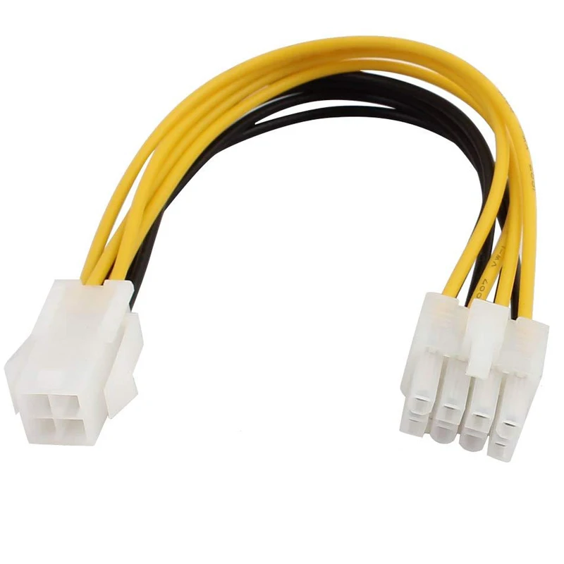 In this case, there is a need
to add encapsulation on cells aftermarket coverglass.
tTherefore, the first option will be considered as our solution if the
budget enables it. Otherwise, the second option will be considered even
if it induce an increase of risk of mission failure.
PV Feasibility Study Download
You can find below the study of two kind of PVs Ultra Triple Junction
Solar cell from Spectrolab, and ISIS TJ 3G30A
The results calculated are the power generated by only one face of the
CubeSat. However the CubeSat has 5 sides with solar panels and between
one and three sides can be under Sunlight at the same time. The number
of sides which receives solar power is related to the orientation of the
CubeSat. To estimate the power generated by the entire CubeSat, the
calculations have to take in account the inclination of the satellite,
in other words, the angles (here in spherical coordinates).
Battery
To supply the modules in energy, at least one rechargeable battery is
needed.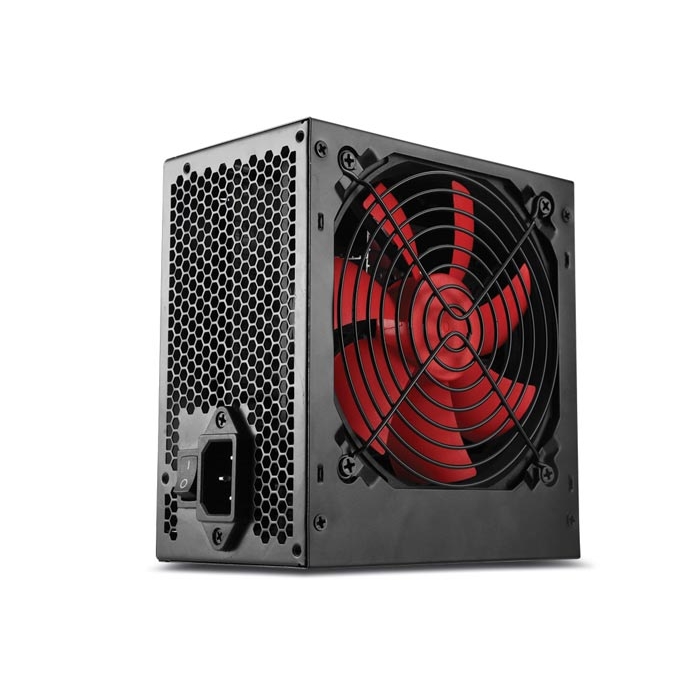 There are different types of batteries (Typically Li-Ion and
NIMH). The technology, the attitude in a cold and hostile environment
and the power consumption have to be considered to size the battery
module.
Since the CubeSats have already a huge rate of failure (due to the
hostile environment that they have to face with), the battery considered
in the ECE³SAT has to be as safe as possible technology designed for
space.
Energy needed
There is not a Power Budget for the ECE CubeSat, therefore an average of
the precedent CubeSat is used:
For improving the battery lifespan, it has to be neither fully charged
nor depth discharged. Precisely, the level of charge needs to be
maintained between 20% and 90% of the total capacity. According to the
amount of energy needed by the system, this should represent 70% of the
battery capacity. Then, in consequence the battery should deliver 3.21
Wh.
Energy used
To improve the lifespan of the battery, it has to be neither fully
charged nor depth discharged.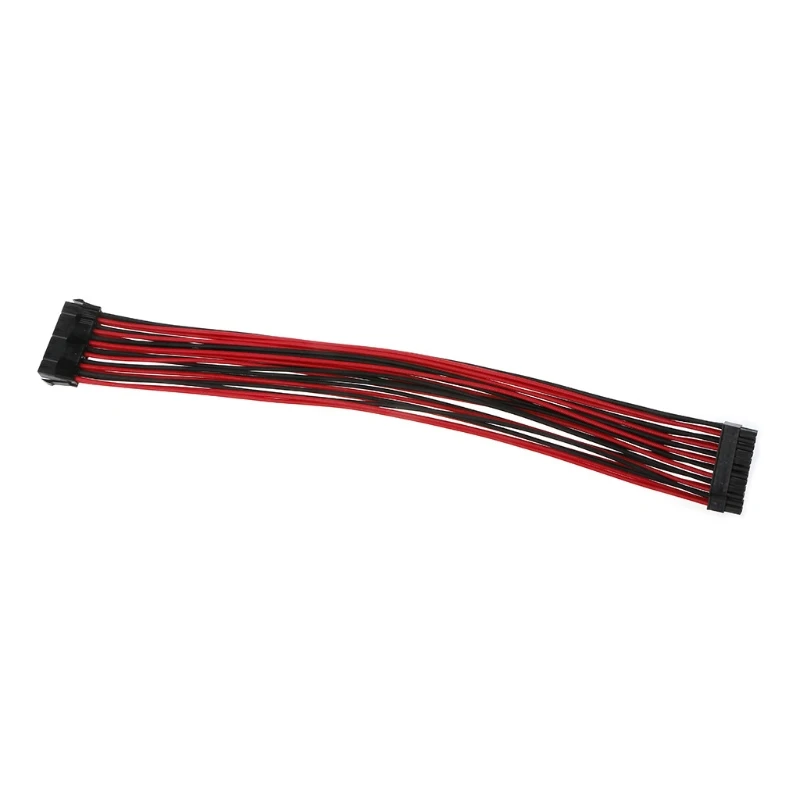 The level of charge needs to be maintained
between 20% and 90% of the total capacity.
Moreover, in average, 2.25Wh will be needed during an eclipse
according to the power budget part.
Thus, a battery will be required with 3.21Wh, or a capacity of 0.87
Ah with a voltage of 3.7 V.
It is in adequacy with the 1 Ah generally used.
The CubeSat may also consider the use of a non rechargeable battery to
execute one time operation. It could be very interesting for some
specific operations such as in the detumbling mode in the ECE³Sat case.
So, it would a primary battery of 1Wh.
Vacuum
At low earth orbit, the atmosphere influence at really low level the
space environment. Therefore, LEO is considered to be in vacuum
conditions.
The battery designed for the CubeSat has to be able to charge and to
furnish electricity to modules in these vacuum conditions.
Temperature
The temperature in space is very low and it is important to take into
account during the design of the modules.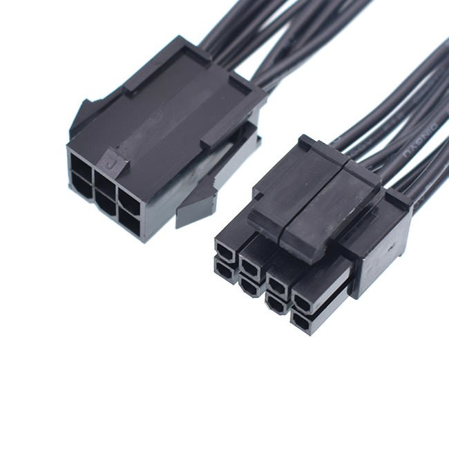 The battery is always
confronted to the natural discharge issue, but in a cold environment
this problem increases. That means that the battery has to be designed
for space, and has to resist to low temperature.
The natural discharge of the battery has to be considered according to
this extreme temperature. The battery should be able to work well and
without too much loss for a temperature of 0 C°. This aims to improve
the charge of battery and avoid the depth of discharge.
Models EPS
To validate the theory, we made some tests with the same type of
components than in our achitecture.
The main purpose of this realization is to study the physical
feasibility of the circuit builded with ISIS. For ensuring precise and
reliable results we simplified a lot the scheme by using only one PV
associated with one MPPT at first. In this way, the energy generated
will charge a 3.7V battery and shall be able to redistribute it into
connectors linked with regulated switch.
To do so, we used:
- CIGS flexible solar cells
- STEVAL ISV006V2 board with a MPPT SPV 1040 and potentiometers
- 3.
 3V Step-Up/Step-down Voltage Regulator
 - 5V Step-Up Voltage Regulator
- Li-Po Battery 3.7V
Solar cells efficiency
First of all, we have to check the efficiency of the CIGS solar cells.
To do so, we used a luxmeter, a multimeter and a load.
CIGS cell is 24 cm by 7.3 cm
Tall
The solar power is of 1W/m² according to the lux meter.
The voltage at the output of the solar cell is of 10V for a 0.2A
current.Then, the cells have a output Power of
Power equation
We can deduce the efficiency of the cell
Efficiency equation EPS
Voltage regulators test
We check the voltage regulation through Voltage 3.3V regulator and
Voltage 5V regulator using both battery or solar cells. The output
voltage of regulators can be regulated only if the current through it is
strong enough to manage the voltage. Therefore, for a bad sunlight (such
as under a 1W light), the regulator cannot works. At the opposite, it
works under the real Sunlight, outside during the day. Therefore the
regulators should also work in space. You can find the description of
the test in the document at the end of the page: Model EPS.
MPPT Board
First Stage: STEVAL-ISV006V2
This device gather both PV (220 mW) and MPPT (SPV1040) on the same
board. You can find below the scheme of the circuit and the top and
bottom view:
We added a connector on the PV input pin for a better handling during
the measurements.
The user can directly act on the circuit by the intermediary of a jumper
and 3 potentiometers (VR4, VR2, VR10)
tAs you can see a jumper named J1 linked a second stage which allows the
battery to be charged or not (the battery can be simulated by the
on-board super capacitor). The jumper allows to discharge manually the
battery or inhibit the charge when PV is illuminated.
Moreover both pins of J1 will be interesting points to take current and
voltage samples on the MPPT (SPC1040) output or battery output. The
device input corresponds to the PV pins.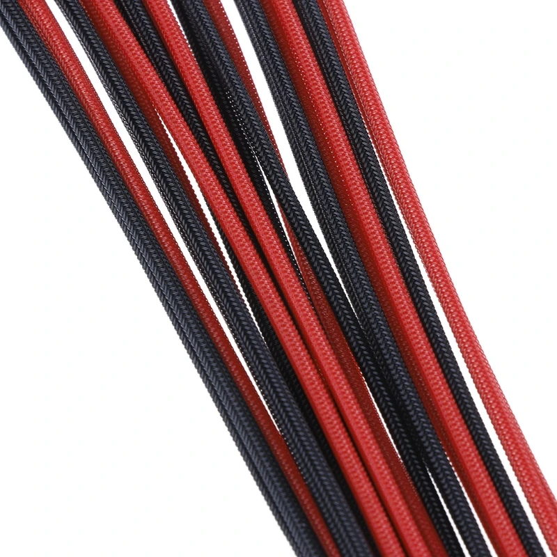
- VR4 (0-1 kΩ)
This variable resistor regulates the input voltage of MPP-SET
(SPV1040 pin). The SPV1040 device is a low power, low voltage,
monolithic step-up converter with an input voltage range from 0.3V
to 5.5 V, capable of maximizing the energy generated by a single
solar cell. The PV shall be illuminated as it generates enough input
voltage to turn on the MPPT (MPP-SET shall see 0.3 V at minimum).
When VR4 equals to zeo, MPP-SET is directly connected to the ground.
After measuring the input voltage, VR4 can be estimated thanks to
the following voltage divider equation:
Equation VMPP-SET - VR2 (0-1 MΩ)
This variable resistor controls the desired ouptu voltage by
regulating the voltage of the pin Vctrl. The algorithm inside the
MPPT will compute the maximum power point according to this value.
With the aid of a multimeter connected to the good pin of the
jumper, we can display the MPPT output voltage. The resistor shall
be configured until the desired ouput is obtained.
- VR10 (0-1 MΩ)
This resistor is connected to the charge regulator and regulate the
amplification of the input signal.
Steval ISV006V2 schematicMPPT top viewMPPT bottom view
What Is EPS12V: Checking Motherboard Power Connectors
EPS12V is a power supply unit designed for entry-level servers and high-power consumption PCs. The EPS12V specification was derived from the ATX form factor, and it was developed by the SSI or Server System Infrastructure forum, a group that includes many different computer companies, including HP and Dell.
In this post, we’ll help you understand what the EPS12V is and how to use it on your computer. Without further ado, let’s get right to it.
Contents
- What Is EPS12V?
- – EPS Explained
- – Using Eight-pin EPS + 12V Power Cable
- – EPS12V Pinout Shapes and Arrangement
- – Connecting Eight-pin EPS12V Cable to a Four-Pin Motherboard Connector
- – Using 4-pin Peripheral Adapters
- – EPS12V and PCIe Connectors
- – EPS12V vs PCIe Connection
- – Using the ATX12V
- – ATX12V Shapes and Arrangement
- EPS12V vs ATX12V
- Conclusion
What Is EPS12V?
EPS12V version specifies two more four-pin 12V connectors for motherboards that require more power.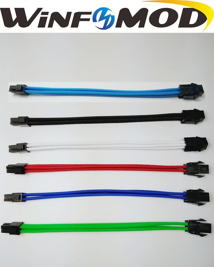 One of these two additional four-pin 12V connectors is required on 850W+ power supply units, while the second is needed on 700-800 watts PSUs.
– EPS Explained
Entry-Level Power Supply Specification, otherwise known as EPS, is a PSU standard that provides critical-based applications and systems with a stable environment while cranking up their power.
EPS power supplies are often designed with an eight-pin 12V connector and a 24-pin motherboard power connector.
In theory, EPS power supplies are compatible with ATX12V and ATX motherboards found in offices and homes.
However, there may be mechanical problems when you connect an EPS12V PSU to an ATX board, especially if the board is from an older generation.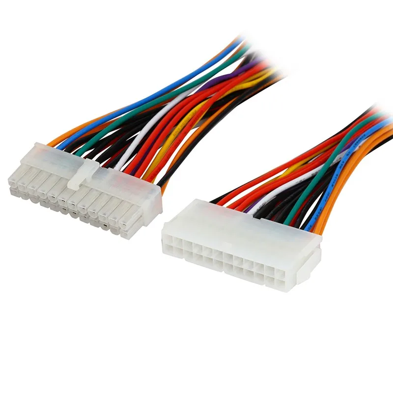
You risk the board’s connector overhanging the socket. To overcome this issue, many PSU vendors utilize connectors in areas where possible to unclip the extra sections. There is no -5V rail for the EPS standard.
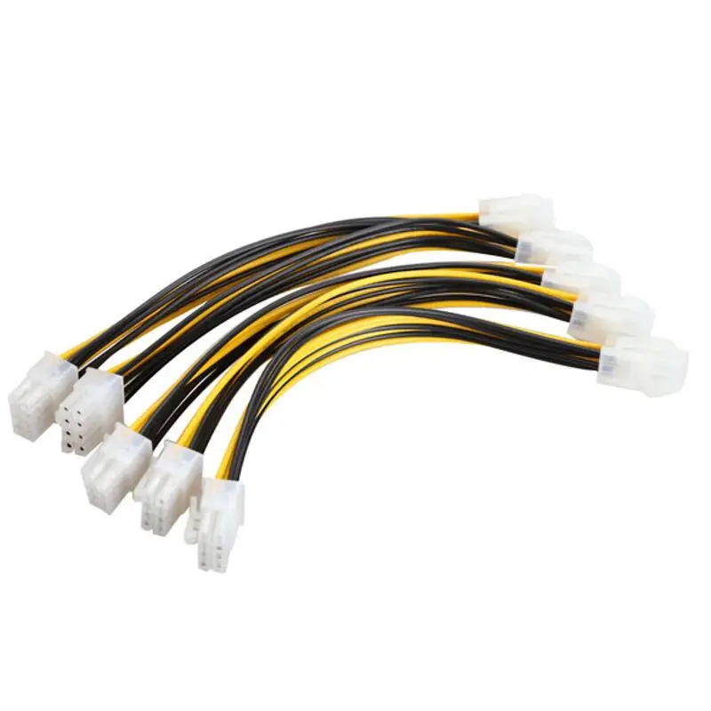
– Using Eight-pin EPS + 12V Power Cable
The eight-pin EPS12V power cable was originally designed for workstations so they could provide multiple CPUs with 12 volts of power. However, thanks to the advancement in technology, many CPUs now require more 12-volt power, thereby making the eight-pin 12-volt cable the ideal choice instead of the four-pin 12V cable. The eight-pin EPS12V comes in two variants depending on the power supply.
There’s the variant where only one 12-volt rail is included in all eight pins and a different variant where two 12-volt rails come in four pins apiece.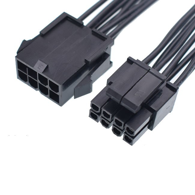
Thanks to the fact that the eight-pin 12V cable is polarized, you can connect it directly to your motherboard’s 8-pin connector.
– EPS12V Pinout Shapes and Arrangement
Of these eight pins, four pins often have a square shape while the remaining four have rounded corners. Your motherboard connector should also have the same shapes and arrangement so the cable can fit in correctly.
While these correct shapes and arrangements are usually the case, you can plug an incorrect arrangement into the connector with a little bit of force, though it’s not guaranteed to work.
The eight-pin cable comes with enough pins to make sure you don’t connect it to your motherboard the wrong way.
You should make sure the square and rounded patterns match the exact same patterns on your motherboard.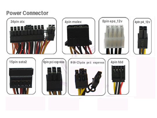
While some of your motherboard connectors, such as the 24-pin main power connector and the 20-pin main power connector, may have the same type of patterns as the EPS12V header, the eight-pin EPS cable should be plugged in its correct socket to make sure none of your components get fried.
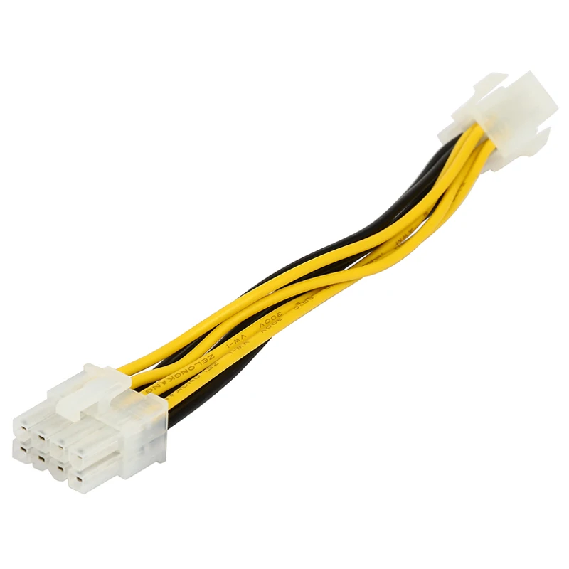
– Connecting Eight-pin EPS12V Cable to a Four-Pin Motherboard Connector
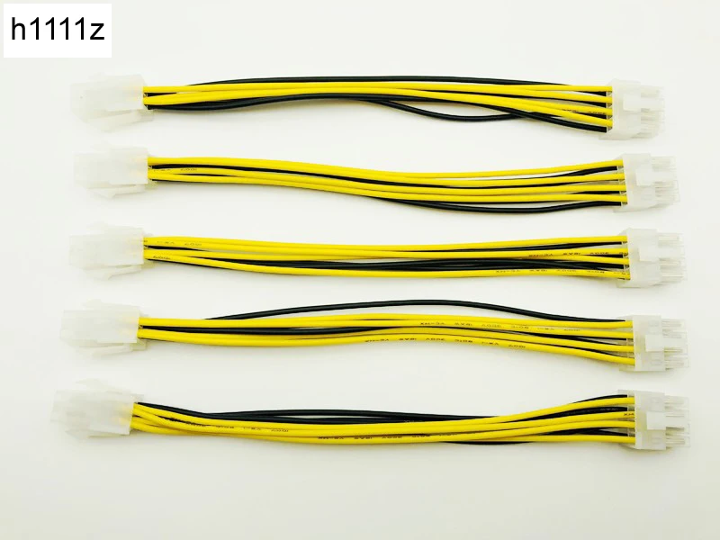
You can also connect the eight-pin 12 volts cable to a four-pin 12-volt motherboard connector. In this situation, only four of the pins on your eight-pin cable will fit into the four-pin MOBO connector, while the remaining four pins that are unconnected will hang off the end of the connector.
Note that you can only fit one end of the eight-pin cable into the four-pin connector on your motherboard.
There’s usually a component that helps you block off the area where the remaining four-pin will hang off.
And there are cases where the plastic end of the four-pin connector on your motherboard would be just too thick, so you won’t need the component to sit between the pins of the eight-pin cable.
– Using 4-pin Peripheral Adapters
If you’re unable to get an eight-pin EPS cable, you can use a four-pin peripheral adapter instead.
This adapter helps you convert two four-pin peripheral power cables into an eight-pin 12V cable.
However, if you choose to use this adapter, make sure to plug the four-pin peripheral connectors into different power supply cables.
If you connect both four-pin peripheral power cables into the same PSU cable, you’ll be pulling the power needed for an entire 8-pin 12 volts connector through one 18-gauge wire.
While there may be no immediate effects, it may not be the safest method in the long run.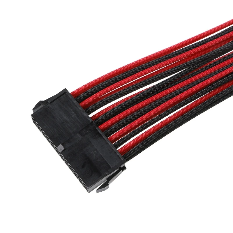
– EPS12V and PCIe Connectors
While the EPS connector is designed to provide the motherboard’s CPU socket with power, the PCI Express connector is built to provide power to the GPU.
Make sure you never try to connect an eight-pin EPS cable to a video card’s eight-pin PCIe power connector.
While the cables for both components may look very similar, they don’t work well with each other. Many people get both cables confused and end up frying their PC components.
The eight-pin PCIe cable is often labeled to make sure that it is not mistaken for the eight-pin EPS cables.
The PCIe cables usually come with a label that says “PCI-E” on their connectors.
If you’re unable to find any label on the connector, you can use the color-coded wires to tell whether or not they are EPS cables or PCIe cables.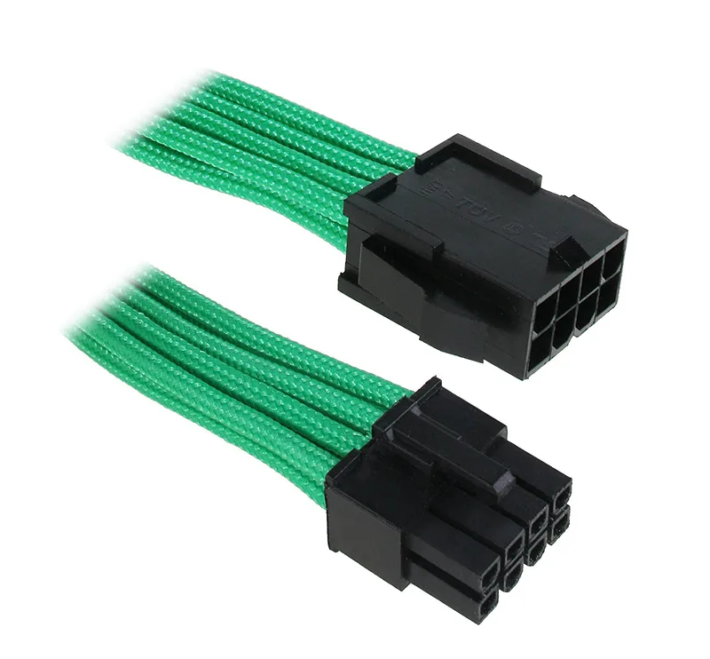
A typical eight-pin EPS cable features yellow wires on the side that has the connector clip, while an eight-pin PCI Express cable would have black wires on the side with the connector clip.
– EPS12V vs PCIe Connection
Besides their appearance, the way both cables are keyed into their connectors is also different, so it would be difficult for you to plug a PCIe cable into an EPS connector or vice versa, except you force the cables. The square and rounded-off connectors of both cables and motherboard connectors are designed so you won’t be able to connect one to the other.
While forcing the cables may allow you to plug the wrong cable into the wrong connector, it’s important to note that both the PCIe and EPS cables and connectors are not compatible with each other and can cause serious damage to your rig.
Both power connectors may offer 12 volts of power, but the row of pins close to the clip of the PCI express connector is ground, while the bottom offers the 12 volts of power.
On the EPS connector, the arrangement is the opposite, with the bottom being ground and the clip side being 12V.
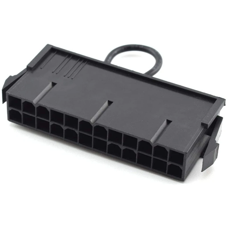
– Using the ATX12V
Before the introduction of the newer 12V power cable, only one 12-volt line was used to provide power to the motherboard.
With the advent of a newer 12 volts cable, there were now two power cables, which allowed more load to be moved to 12 volts.
Most of the power coming from the 12V connector is often used to power the CPU. However, some motherboards dedicate the power to other things as well.
Having the new 12V connector on a motherboard meant that your motherboard was an ATX12V motherboard.
If your motherboard is designed with an ATX12V connector, then you’ll need to plug an ATX power cable into the connector, or else your processor would get no power.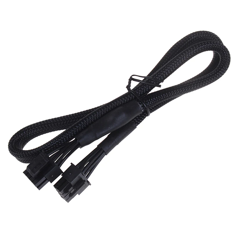 There was one exception, however.
When the connector was newly made, some motherboards featured an alternative in the form of a socket that allowed you to plug in a four-pin peripheral power cable.
This solution allowed and still allows people with older power supplies that didn’t and don’t have the four-pin 12-volt cable to power their components.
– ATX12V Shapes and Arrangement
The four-pin 12-volt cable comes in a polarized design, so you can’t plug it into any other connector except a four-pin motherboard connector. There are two pins with rounded corners and two pins with a square shape.
The motherboard connectors they connect to also come with the same design and arrangement, so you can only connect the cable correctly as long as you don’t forcefully connect it the wrong way.
While the square and rounded pattern arrangement on the ATX12V pins may match various arrangements on other motherboard connectors, such as the 24-pin main power connector and the 20-pin main power connector.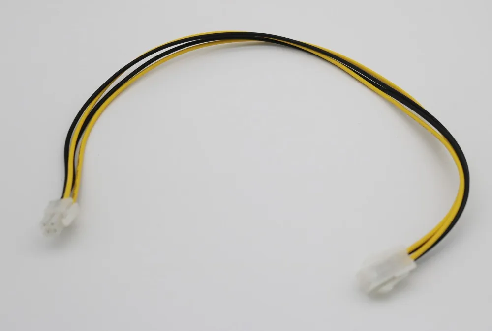
It’s recommended that you only plug it into the rightful four-pin connector on your motherboard if you don’t want to fry your components.
You can also use a four-pin peripheral adapter to connect a four-pin 12 volts cable to your power supply if your PSU doesn’t have a four-pin 12V cable.
EPS12V vs ATX12V
While it’s possible to plug the four-pin 12 volts of an ATX12V cable into an eight-pin EPS motherboard, there’s no guarantee that the former would work.
If one 12-volt rail is what the motherboard is designed to take, then the four-pin 12-volt cable of an ATX12V may work.
However, if the motherboard is supposed to take up two 12-volt rails, then the four-pin cable won’t work.
Keep in mind that many double CPU motherboards need one 12 volt rail per processor for them to function properly.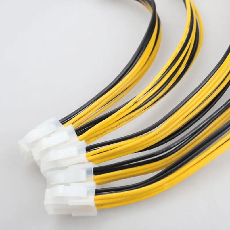
Even if the motherboard ends up working with the four-pin 12-volt cable, you’ll only be providing half the current-carrying capacity the eight-pin EPS cable is capable of providing.
The lack of power can cause your motherboard’s connector and the four-pin cable to overheat, leading to melted or scorched connectors.
Motherboards with eight-pin EPS connectors expect a significant amount of power. You’ll be taking a great risk by plugging in a four-pin cable.
Besides the fact that the four-pin cable won’t supply enough power, it can only sit on one end of the eight-pin connector.
And sometimes, the pin arrangement won’t align with how the connector pins are arranged.
Conclusion
With this post, you’ve learned EPS12V meaning as well as the difference between EPS modular power and other power supply units.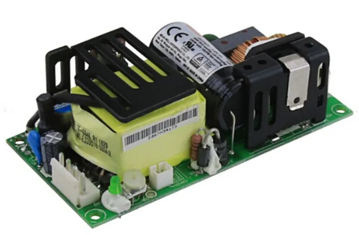
Here’s a summary to make sure you have all you need:
- EPS12V comes with eight-pin connectors that require an eight-pin cable with the same pin arrangement
- You cannot connect an EPS cable into a PCIe connector or vice versa
- Connecting an ATX12V cable into an EPS12V motherboard connector isn’t recommended and may not work
- ATX12V features a four-pin connector that requires a four-pin cable with the same pin arrangement
Always make sure you plug in the right power supply cable into the right motherboard connector to avoid damaging your PC components.
Remember that the EPS12V doesn’t have a label, while the PCI Express tends to have a label depicting that it’s a PCIe connector or cable.
EPS-45S-48
Make a request for
source of power
Quantity
Your name
Email
Phone number
Organization
Order comments
By submitting this form, I agree to the
personal data processing policy
Application successfully sent.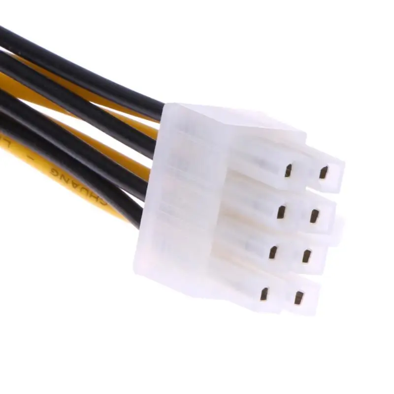
An error has occurred. Try later.
Email does not match the format.
Confirm your consent to the processing of personal data.
Fill in required fields.
Specifications
| Output: | |
|
DC voltage |
48V |
|
Rated current |
0. 94A 94A
|
|
Rated power |
45.1W |
|
Output noise level |
300mVp-p |
|
Voltage adjustment range |
45. 6-52.8V 6-52.8V
|
|
Voltage tolerance |
±1.0% |
|
Mains output voltage instability |
±0.5% |
|
Load instability |
±0.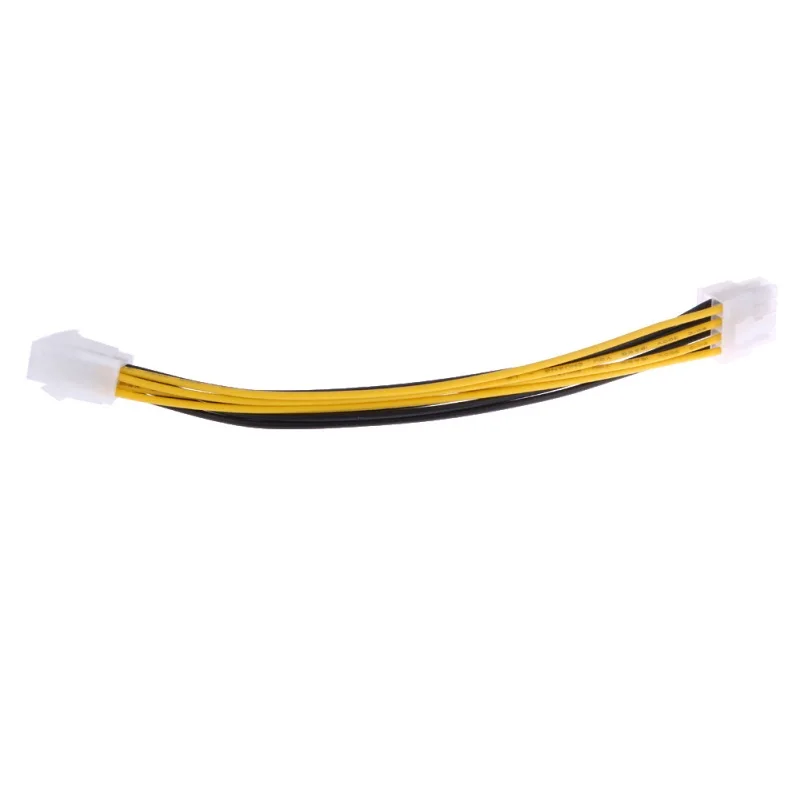 5% 5%
|
|
Settling time, rise time |
500ms, 30ms / 230VAC 500ms, 30ms / 115VAC at full load |
|
retention time |
30ms / 230VAC 12ms / 115VAC at full load |
| Input: | |
|
Input voltage range |
85-264VAC 120-370VDC |
|
Frequency range |
47~63Hz |
|
efficiency |
9one% |
|
Alternating current |
1. 2A/115VAC 1A/230VAC 2A/115VAC 1A/230VAC
|
|
Withstand voltage |
l/P-0/P:3KVAC l/P-FG:2KVAC O/P-FG:0.5KVAC |
|
Starting current |
OLD STAR 30A/115VAC 60A/230VAC |
| Protection: | |
|
Surge protection |
Protection type: Shut down o/p voltage, re-power on to recover |
|
Overload protection |
Protection type : Hiccup mode, recovers automatically after fault condition is removed |
| Ambient conditions Wednesdays: | |
|
Operating temperature range |
-30 ~ +70°C |
|
Operating Humidity |
20 ~ 90% RH non-condensing |
|
Temperature coefficient |
±0.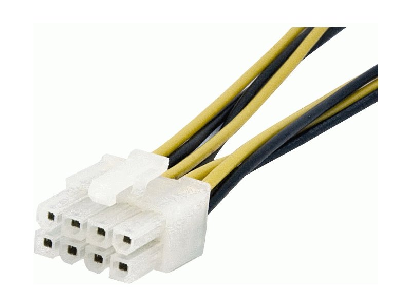 03%/°C (0 ~ 45°C) 03%/°C (0 ~ 45°C)
|
|
Vibration |
10 — 500Hz, 2G 10min./1 cycle, period for60min. each along X, Y, Zaxes |
|
Temperature and humidity conditions of storage |
-40 ~ +85°C, 10 ~ 95% RH |
| Safety and EMF: | |
|
Safety standards |
UL60950-1, TUV EN60950-1 approved |
|
Insulation resistance |
l/P-O/P, l/P-FG, O/P-FG:100M Ohms/500VDC/25°C/70% RH |
|
Electromagnetic compatibility |
Compliance to EN55022 (CISPR22) Class B, EN61000-3-2,-3 |
|
Electromagnetic immunity |
Compliance to EN61000-4-2,3,4,5,6,8,11, heavy industry level, criteria A |
| Other: | |
|
MTBF (Mean Time Between Failures) |
726. 2Khrs min. MIL-HDBK-217F (25℃) 2Khrs min. MIL-HDBK-217F (25℃)
|
|
dimensions |
76.2*50.8*24mm (L*W*H) |
|
Package |
0.11Kg; 120pcs/14.2Kg/0.97CUFT |
EPS-35-5 for 1 336.
 32 ₽ in stock manufactured by MEAN WELL
You can buy a pulse power supply unit 30W EPS-35-5 from the manufacturer MEAN WELL wholesale and retail with delivery throughout Russia, Kazakhstan, the Republic of Belarus and Ukraine, as well as to other countries of the Customs Union (Armenia, Kyrgyzstan, etc.).
In order to buy this product at the base price at retail, put it in the shopping cart and place an order following the detailed instructions. Please note that depending on the increase in the volume of products, the retail price will be recalculated automatically. The wholesale price for a switching power supply 30W 120-370Vdc 85-264Vac EPS-35-5 is set only after sending a commercial request to e-mail: [email protected] or [email protected]
- For more information, see Payment.
We work with all major transport companies and guarantee the efficiency and reliability of each delivery, regardless of the region where the customer is present.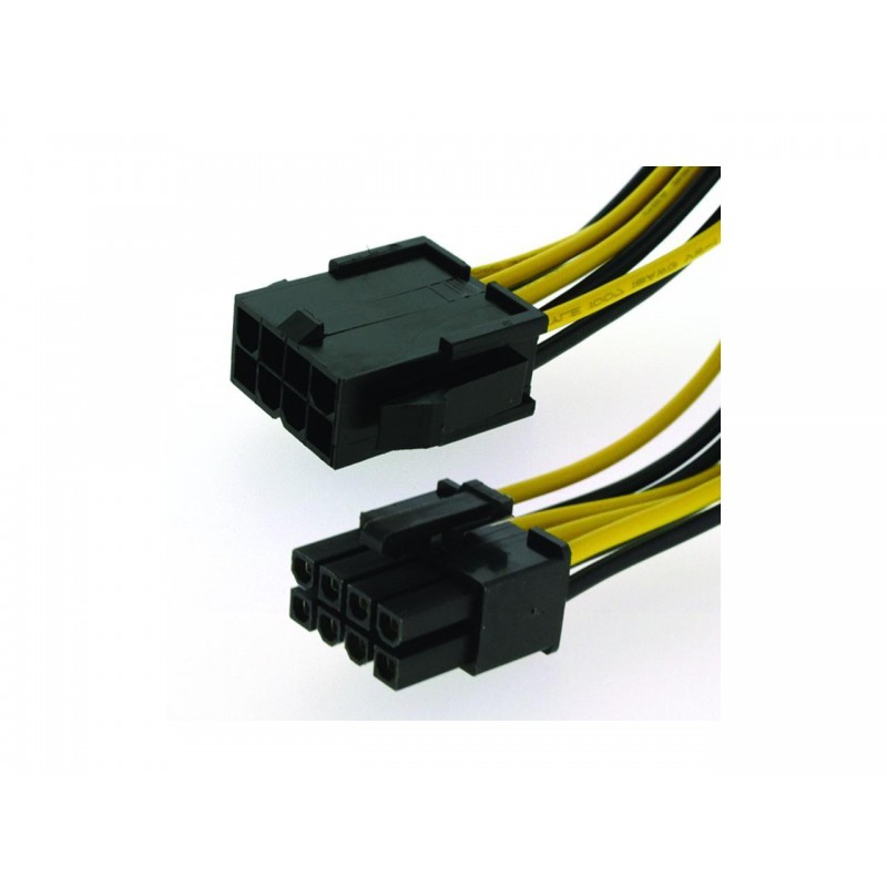 These goods are also delivered from various warehouses in Europe, China and the USA. Please ask SUPPLY24.ONLINE specialists for possible delivery options.
- For more information, see Delivery.
Warranty provided directly by the MEAN WELL manufacturer. Warranty repair or replacement of equipment is carried out only after the examination and establishment of the fact of a warranty case.
- For more information, see Warranty and Warranty Terms.
Open power supplies of almost all well-known world brands are represented by our company. If the product you are interested in was not found on our website, contact the technical support service or your manager and our engineers will select analogues for your equipment. Thus, it is possible to reduce the cost of equipment maintenance by up to 20% and optimize your costs. The SUPPLY24.ONLINE company takes full responsibility for the correct selection of the analogue. Our company offers only a reasonable approach, if, according to a number of criteria, the requested product does not imply a replacement for an analogue, we do not offer a replacement.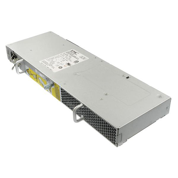
The strategic goal of our company is to help you choose equipment and goods with optimal characteristics, and understand a huge number of commodity items and offers.
Attention!
- Characteristics, appearance and complete set of goods can be changed by the manufacturer without notice.
- Product image is for illustration purposes only and is subject to change without notice.
- See Specifications tab for exact specification.
- If you need to install software and use third-party accessories, please check their compatibility with the device by studying the documentation on the manufacturer’s website MEAN WELL
- It is forbidden to violate the factory settings and adjustments without the involvement of specialists from certified service centers.
Features
Manufacturer
MEAN WELL
Dimensions
see
Installation
Open execution
Power
EPS-35
Operating temperature
-30 .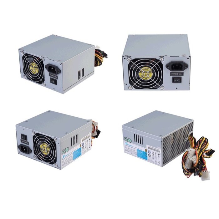 .. 70 ° C
power voltage
85 … 264V AC,
Related goods
BVHH- 21t-P1.1,
Outpatus current
Protection
from KZ,
Outputs
Outpatient voltage
4.75 … 5.5V DC,
External dimensions
76.2×50.8x24mm
Power supply type
pulsed
Type of power supply
without housing
Electrical connection
plug with a pitch of 3.96 mm
DELIVERY IN RUSSIA
goods in a warehouse in the Russian Federation. In some cases, with a large remoteness of your region, the delivery time may be increased.
- A complete list of cities to which delivery is carried out, see below.
DELIVERY TO THE COUNTRIES OF THE CUSTOMS UNION
Delivery is carried out within 3-5 days from the moment the funds are credited to the account of the company to the following countries.
- Kazakhstan
- Armenia
- Belarus
- Kyrgyzstan
Please note that the terms of delivery of goods directly depend on the availability of goods in the Russian warehouse of the company.
If the selected items are located in one of the external warehouses in Europe or the USA, then the delivery time of the goods can be up to 3-4 weeks. To avoid misunderstandings, we recommend that you clarify the current delivery time in the logistics department or with the company manager.
In this case, as a rule, 90% of orders are delivered to customers within the first 2 weeks.
If any part of the goods from your order is not in stock, we will ship all available goods, and after receiving the rest of the order from the external warehouse, we will send it to you at our company’s expense.
DISPOSAL OFFICES:
Delivery to shopping center is free of charge
WAREHOUSES
Mean Well EPS-65S-24 power supply, third of six. Overview and test of the power supply for 24 Volts. Power supply 24V Mean Well
$9.97
Go to store
And so, today I have in my hands the third power supply and six sent to me by one of my readers. In this case, we will talk about a relatively compact and inexpensive power supply, I would even say that this unit belongs to the budget series, since to some extent it is noticeably simpler than the previous ones. But simpler does not always mean worse, and I will try to show and explain all this in the course of the review.
In general, who are interested in branded power supplies, I think they will find something new for themselves.
In fairness, this review is the third only conditionally, since before that I had already reviewed the power supply from this company, but since there are reviews from one batch of six pieces, the review is called — the third of six 🙂
More I would like to thank Vladimir, without whom this series would not have been possible. Anyway, I somehow thought that there are a lot of reviews of «Chinese» power supplies, but there is a failure with branded ones, but they are also of interest, not only for the quality of work, but also for circuitry solutions different from Chinese «comrades».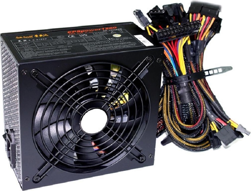 That’s why I think that reviews of branded power supplies are also very useful and I’m glad that I can fill this gap.
The power supply was bought on Taobao, but if the previous two were bought from one seller, then the one being reviewed is already from another.
The packaging is simple, of course worse than a cardboard box, but better than bubble wrap.
Externally, the power supply looks great, no damage. However, the manufacturer fills its power supplies with sealant in such a way that nothing moves in it at all and it is also very problematic to break off anything.
High efficiency, up to 91% depending on the output voltage, as well as power consumption without load, only 0.1 watts.
In addition, there is protection against overload, short circuit and overvoltage.
The power supply is designed for passive cooling and operation in the temperature range from -30 to +70.
Full specifications are available on the datasheet, but I’ll just quote some key pages from it.
Judging by the description, the power supply is available with seven output voltage options, but I will review the 24 Volt version.
You can also notice that the power supply works out the declared power only in the version with voltages of 12 volts and higher. At lower voltages, the power can even be two times lower than the declared one, for example, for the 3.3 Volt version.
This power supply is a variation of the EPS-65 version, which has a slightly different design.
The power supply is made in the form factor 2×3 inches, or about 50x75mm and belongs to the compact series.
For comparison, I put a pair of Minvel power supplies with a power of 100 and 120 watts on the left, and on the left a Chinese version with a declared power of 72-96 watts, the so-called «folk».
Dimensional drawing of power supplies of this series. It can be seen that the power supply is very compact, for example, the total height is only 27mm.
But let’s move on to a more detailed examination.
At the input there is an almost full-fledged filter, perhaps only a protective varistor is missing.
As expected, there is a thermistor to limit the inrush current and an X type capacitor. There are two two-winding chokes, a small one is turned on immediately after the power input, a large one is between the X capacitor and the diode bridge.
The input capacitor has a specification sticker. The capacitance of the input capacitor is 82 microfarads, taking into account the output power of 65 watts and the full range of input voltage, I would say that this is not enough.
I thought I saw a lot of different power supplies, but they still never cease to amaze me. In this case, I came across a very unusual choke. The fact is that it is wound not with an ordinary wire, but with a thin tire, a very unusual solution.
No, of course I have seen transformers whose windings are wound with a busbar or thick foil, but here the busbar is laid perpendicular to the frame. ..
..
the power of the power supply.
2. Output diode assembly MBR20200, 200 Volt 20 Amp, which is very good for an output current of 2.7 Ampere. To the right you can see a place for another diode assembly, it is presumably installed in low-voltage versions of power supplies.
3. There is also a pair of feedback optocouplers, one is responsible for voltage stabilization, the other for overvoltage protection.
4. Another unusual thing I saw in this block. Interwinding capacitors are not one or even two, but four.
The bottom pair is included as standard, between the minus of the input filter capacitor and the common output wire. But the second pair is connected at one end between the noise suppression chokes, while the other side also goes to the common output wire.
The solution is somewhat extraordinary, I have not seen this before.
Above, I wrote that a 13N60M2 transistor was used. By and large, the most common high-voltage transistor, if not for what case it comes in. The most common isolated TO-220 is installed here, but it turns out that there is also a shortened version, which I also did not come across before.
And here the designers surprised me once again, but this time not very pleasantly. The fact is that a diode assembly is installed at the output of the power supply and it is quite logical that it is installed on a radiator. Since the power supply has modifications with a large output current, the designers have installed a very decent radiator, which is good.
But the fact that it not only goes to the «hot» side, but also has insulation only in the form of adhesive tape, surprised me greatly, especially considering the scrupulous attitude of this company to the safety of its products.
The radiator is fixed with a special sealant and installed very rigidly, but in my opinion this solution is closer to «Chinese» crafts than to a proprietary device.
1. After the diode assembly, there is a pair of 390 microfarad capacitors at 35 Volts, manufactured by Rubicon, however this was predictable: There is also a choke to reduce the level of output ripple.
2. To the left, another capacitor is installed, with a capacity of 100 μF, which is connected after the inductor, as well as an LED and a tuning resistor for setting the output voltage.
Another couple of photos of the power supply in the top view.
Everything is neat from below, although I did not doubt it. The board is clean, there are protective slots in the «narrow» places.
1. Controls the operation of the PWM controller 46BL065. This is a quasi-resonant PWM controller, but what is curious, although it has a different name, according to the conclusions, it completely coincides with the NCP1239 PWM controller, which is installed in the RPS-120-27 power supply. But at the same time, NCP1239 is not quasi-resonant.
2. Another place that surprised me in this power supply. The
PWM controller is often able to monitor the input voltage in order to protect against operation when the input voltage is too low. But usually the voltage across the input capacitor of the filter is measured. But here the alternating voltage is controlled, up to the diode bridge. To do this, there are two diodes on the board, the cathodes of which are connected and go to the PWM controller.
Everything would be fine, but this feature gave rise to at least two problems:
1. When the PWM input voltage fails, the controller immediately blocks the operation, and does not wait until the capacitor is discharged. Therefore, this PSU is worse for a short-term loss of power at the input. In fact, everything is given «at the mercy» of the output capacitors.
2. Since the PWM controller is immediately blocked, and there is no one to discharge the capacitor, it remains energized even after the power is turned off. And even after 12 hours, there is a residual voltage of 250-260 Volts on it!
I found out about this by accident when I decided to discharge the capacitor before measuring its capacitance. The result for me was somewhat …. unexpected.
There is a third problem. The fact is that there is no one to discharge the input X capacitor either, so if you remove the power plug from the network and immediately touch its contacts, you can “pinch” a little
In general, the developers surprised me once again. The above features do not affect the quality of work, but in my opinion they are unpleasant.
Another small observation, the capacitor after the output choke is connected somewhat incorrectly, since there is a rather long path in series with it. In theory, it should be closer to the output connector.
But as the tests showed, everything worked fine, although this can usually increase the amplitude of the ripple and the noise level a little.
The block diagram is present in the instructions for the power supply and it basically differs from the same RPS-120-27 in the absence of a thermal protection circuit.
Yes, this power supply does not have overheating protection, which is also unusual for Minwell products.
Since the power supply is relatively simple, I drew a complete circuit diagram of it. Of course, there may be some errors, but I tried to transfer it carefully up to the positional designations of the components.
At a cursory glance, we can say that we have before us the most common power supply circuit, if not for one more minor nuance. Not only is there no output load resistor, but for modern power supplies it is not really needed. But the value of the resistor in series with the power-on indication LED is as much as 680 kOhm, when 2-10 kOhm is usually set. Apparently again the struggle for low energy consumption at idle.
Before proceeding to the tests, a small photo to explain what and where is located in this power supply.
The output voltage adjustment range is very decent. at the base 24 Volts, you can set the output voltage from 21.1 to 28.4, while the adjustment is smooth.
The first test with which I will check the dependence of the output voltage on the load current, as well as measure the efficiency of the power supply and power factor.
The test used one of my electronic loads, a wattmeter and two multimeters to measure current and voltage simultaneously.
In this case, the test was carried out both at a voltage of 225-230 Volts, and at a voltage of about 108-110.
Judging by the results, the power supply has not only high efficiency, but also quite good output voltage stability. The output voltage difference over the full load range is only about 30mV.
Efficiency measurement results at 110 volts may not be very accurate, since the Wattmeter does not work quite correctly in this mode.
The next test is to measure the ripple level at the output of the power supply.
First, what does the idle output look like. A small low-frequency saw is visible, since the controller is in «green mode», but unlike the RPS-120-27, this power supply is quiet, the noise is noticeable only in the current range from 50 to 150 mA.
I will hide the main part of the waveforms under the spoiler, since they are given simply as an addition.
Waveforms
Summary of RF and LF ripple at 230/110 V input and 100% load.
1.2 — 230 Volts
3, 4 — 110 Volts
I can note a low ripple range, especially against the background of what was stated in the description for the power supply.
For a 24 Volt model, a swing of no more than 240 mV is declared, in fact the result was about four times less.
As usual, at the end of the review, I present the results of the thermal run. The tests were carried out classically, for 20 minutes each, followed by temperature measurement and an increase in the load current. The power supply was covered with a lid to simulate a closed volume.
Here I will digress a little. The instruction indicates rather severe restrictions in terms of the operating conditions of the power supply. For example, when the ambient temperature exceeds 50 degrees, it is necessary to reduce the load current. But in addition, such restrictions also apply when the input voltage is reduced. For example, with my test voltage of 108-110 Volts, the output power should be reduced to 90% of the maximum continuous. In this case, at a level of about 60 watts.
In fact, I did not reduce the load power, moreover, when powered by 230 Volts, I even loaded it with a current of 3 Amperes, and not 2. 7, as stated by the manufacturer. And in my opinion, the power supply normally survived all this, starting to give up only at extreme operating conditions.
At a voltage of 230 volts, the high-voltage transistor was the first to overheat, although it is still far from a critical state.
When the voltage was reduced to 110 volts, the heating of the diode bridge predictably increased, as the current through it increased.
The rest of the components did not have very high temperatures, so I believe that by increasing the area of the radiator in the «hot» part, you can get more power output without overheating.
Thermal photo after run at 230 Volts
And after run at 110 Volts.
As before, I ran a DC test to determine the maximum output current.
1, 2. With an input voltage of 230 Volts, the PSU turned off at 3.878 Amps.
3, 4. At 110 volts, the shutdown was a little earlier, 3.569Ampere.
In both cases, the power supply turned off abruptly, and the output voltage until the moment of shutdown was the original 24 Volts, this can be seen not in the first and third photos.
After the overload was removed, the power supply automatically restored operation.
Just for fun, I made a GIF for checking for a short circuit.
Let me sum up the results of the tests.
The power supply passed all tests, showed good quality of output voltage stabilization, low heating, small ripple range, and high efficiency.
By and large, in terms of work, I really have nothing to complain about, but in terms of «features» there are some comments.
Firstly, the absence of discharge circuits in parallel with the input capacitor, this does not affect operation, but it does affect safety.
Secondly, the design of the heatsink of the output diode assembly is not very good, also a note on safety.
And thirdly, the lack of thermal protection, which is also not very good, although the power supply does not overheat in operation.
Personally, in my opinion, such a Bp is perfect for building compact soldering stations with T12 soldering irons.
That’s all for me, I will be glad to ask questions and just comments, I hope that the review was useful.
$9.97
Go to the store
MeanWell EPS-65S-24 power supply, third of six
And so, today I have in my hands the third power supply and six sent to me by one of my readers. In this case, we will talk about a relatively compact and inexpensive power supply, I would even say that this unit belongs to the budget series, since to some extent it is noticeably simpler than the previous ones. But simpler does not always mean worse, and I will try to show and explain all this in the course of the review.
In general, who are interested in branded power supplies, I think they will find something new for themselves.
In fairness, this review is the third only conditionally, since before that I had already reviewed the power supply from this company, but since there are reviews from one batch of six pieces, the review is called the third of six 🙂
Once again, I would like to thank Vladimir, without whom this series would not have been possible. Anyway, I somehow thought that there are a lot of reviews of “Chinese” power supplies, but there is a failure with branded ones, but they are also of interest, not only for the quality of work, but also for circuitry solutions different from Chinese “comrades”. That’s why I think that reviews of branded power supplies are also very useful and I’m glad that I can fill this gap.
The power supply was bought on Taobao, but if the previous two were bought from one seller, then the one being reviewed is already from another.
The packaging is simple, of course worse than a cardboard box, but better than a bubble wrap.
Externally, the power supply looks great, no damage. However, the manufacturer fills its power supplies with sealant in such a way that nothing moves in it at all and it is also very problematic to break off anything.
High efficiency, up to 91% depending on the output voltage, as well as power consumption without load, only 0. 1 watts.
In addition, there is protection against overload, short circuit and overvoltage.
The power supply is designed for passive cooling and operation in the temperature range from -30 to +70.
Full specifications are available on the datasheet, but I’ll just quote some key pages from it.
Judging by the description, the power supply is available with seven output voltage options, but I will review the 24 Volt version.
You can also notice that the power supply works out the declared power only in the version with voltages of 12 volts and above. At lower voltages, the power can even be two times lower than the declared one, for example, for the 3.3 Volt version.
This power supply is a variation of the EPS-65 version, which has a slightly different design.
The power supply is made in the form factor 2×3 inches, or about 50x75mm and belongs to the compact series.
For comparison, I put a pair of Minvel power supplies with a power of 100 and 120 watts on the right, and on the left a Chinese version with a declared power of 72-96 watts, the so-called «folk».
Dimensional drawing of power supplies of this series. It can be seen that the power supply is very compact, for example, the total height is only 27mm.
But let’s move on to a more detailed examination.
At the input there is an almost full-fledged filter, perhaps only a protective varistor is missing.
As expected, there is a thermistor to limit the inrush current and an X type capacitor. There are two two-winding chokes, a small one is turned on immediately after the power input, a large one is between the X capacitor and the diode bridge.
There is a sticker with technical characteristics on the input capacitor. The capacitance of the input capacitor is 82 microfarads, taking into account the output power of 65 watts and the full range of input voltage, I would say that this is not enough.
I thought I saw a lot of different power supplies, but they still never cease to amaze me. In this case, I came across a very unusual choke. The fact is that it is wound not with an ordinary wire, but with a thin tire, a very unusual solution.
No, of course I have seen transformers whose windings are wound with a busbar or thick foil, but here the busbar is laid perpendicular to the frame …
.
2. Output diode assembly MBR20200, 200 Volt 20 Amp, which is very good for an output current of 2.7 Ampere. To the right you can see a place for another diode assembly, it is presumably installed in low-voltage versions of power supplies.
3. There is also a pair of feedback optocouplers, one is responsible for voltage stabilization, the other for overvoltage protection.
4. Another unusual thing that I saw in this block. Interwinding capacitors are not one or even two, but four.
The bottom pair is included as standard, between the minus of the input filter capacitor and the common output wire. But the second pair is connected at one end between the noise suppression chokes, while the other side also goes to the common output wire.
The solution is somewhat extraordinary, I have not seen this before.
Above, I wrote that the 13N60M2 transistor was used. By and large, the most common high-voltage transistor, if not for what case it comes in. The most common isolated TO-220 is installed here, but it turns out that there is also a shortened version, which I also did not come across before.
And here the designers surprised me once again, but this time not very pleasantly. The fact is that a diode assembly is installed at the output of the power supply and it is quite logical that it is installed on a radiator. Since the power supply has modifications with a large output current, the designers have installed a very decent radiator, which is good.
But the fact that it not only enters the “hot” side, but also has insulation only in the form of adhesive tape, surprised me greatly, especially considering the scrupulous attitude of this company to the safety of its products.
The radiator is fixed with a special sealant and installed very rigidly, but in my opinion, this solution is closer to «Chinese» crafts than to a proprietary device.
1. After the diode assembly, there is a pair of 390 microfarad capacitors at 35 Volts, manufactured by Rubicon, however, this was predictable: There is also a choke to reduce the level of output ripple.
2. To the left, another capacitor is installed, with a capacity of 100 microfarads, which is connected after the inductor, as well as an LED and a tuning resistor for setting the output voltage.
Another couple of photos of the power supply in the top view.
Everything is neat from below, although I did not doubt it. The board is clean, there are protective slots in the «narrow» places.
1. Controls the operation of the PWM controller 46BL065. This is a quasi-resonant PWM controller (presumably), but what is curious, although it has a different name, according to the conclusions, it completely matches the NCP1239 PWM controller, which is installed in the RPS-120-27 power supply.
2. Another place that surprised me in this power supply.
The PWM controller is often able to monitor the input voltage in order to protect against operation when the input voltage is too low. But usually the voltage across the input capacitor of the filter is measured. But here the alternating voltage is controlled, up to the diode bridge. To do this, there are two diodes on the board, the cathodes of which are connected and go to the PWM controller.
Everything would be fine, but this feature gave rise to at least two problems:
1. When the PWM input voltage fails, the controller immediately blocks the operation, and does not wait until the capacitor is discharged. Therefore, this PSU is worse for a short-term loss of power at the input. In fact, everything is given «at the mercy» of the output capacitors.
2. Since the PWM controller is immediately blocked, and there is no one to discharge the capacitor, it remains energized even after the power is turned off. And even after 12 hours, there is a residual voltage of 250-260 Volts on it!
I found out about this by accident when I decided to discharge the capacitor before measuring its capacitance. The result for me was somewhat … unexpected.
There is a third problem. The fact is that there is no one to discharge the input X capacitor either, so if you remove the power plug from the network and immediately touch its contacts, you can “pinch” a little
In general, the developers surprised me once again. The above features do not affect the quality of work, but in my opinion they are unpleasant.
Another small observation, the capacitor after the output choke is connected somewhat incorrectly, since there is a rather long path in series with it. In theory, it should be closer to the output connector.
But as tests showed, everything worked fine, although usually this can slightly increase the range of ripples and the level of interference.
The block diagram is present in the instructions for the power supply and it basically differs from the same RPS-120-27 in the absence of a thermal protection circuit.
Yes, this power supply does not have overheating protection, which is also unusual for Minwell products.
Since the power supply is relatively simple, I drew a complete circuit diagram of it. Of course, there may be some errors, but I tried to transfer it carefully up to the positional designations of the components.
At a cursory glance, we can say that we have before us the most common power supply circuit, if not for one more minor nuance. Not only is there no output load resistor, but for modern power supplies it is not really needed. But the value of the resistor in series with the power-on indication LED is as much as 680 kOhm, when 2-10 kOhm is usually set. Apparently again the struggle for low energy consumption at idle.
Before proceeding to the tests, a small photo to explain what and where is located in this power supply.
The output voltage adjustment range is very decent. at the base 24 Volts, you can set the output voltage from 21.1 to 28.4, while the adjustment is smooth.
The first test with which I will check the dependence of the output voltage on the load current, as well as measure the efficiency of the power supply and power factor.
The test used one of my electronic loads, a wattmeter, and two multimeters to measure current and voltage simultaneously.
In this case, the test was carried out both at a voltage of 225-230 Volts, and at a voltage of about 108-110.
Judging by the results, the power supply has not only high efficiency, but also quite good output voltage stability. The output voltage difference over the full load range is only about 30mV.
The results of measuring the efficiency at a voltage of 110 volts may not be very accurate, since the Wattmeter does not work quite correctly in this mode.
The next test is to measure the ripple level at the output of the power supply.
First, what does the idle output look like. A small low-frequency saw is visible, since the controller is operating in “green mode”, but unlike the RPS-120-27, this power supply is quiet, the noise is noticeable only in the current range from 50 to 150 mA.
I will hide the main part of the waveforms under the spoiler, since they are given simply as an addition.
Waveforms
All waveforms were taken at 25%, 50%, 75% and 100% load.
HF ripple at 230V input voltage
LF ripple
Supply voltage 110V
HF ripple
LF ripple
Combined pattern of HF and LF ripple at 230/110 Volts input voltage and 100% load.
1.2 — 230 Volt
3, 4 — 110 Volts
I can note a low ripple range, especially against the background of what was stated in the description for the power supply.
For a model with a voltage of 24 Volts, a swing of no more than 240 mV is declared, in fact, the result was about four times less.
As usual, at the end of the review, I present the results of the thermal run. The tests were carried out classically, for 20 minutes each, followed by temperature measurement and an increase in the load current. The power supply was covered with a lid to simulate a closed volume.
Here I will make a small digression. The instruction indicates rather severe restrictions in terms of the operating conditions of the power supply. For example, when the ambient temperature exceeds 50 degrees, it is necessary to reduce the load current. But in addition, such restrictions also apply when the input voltage is reduced. For example, with my test voltage of 108-110 Volts, the output power should be reduced to 90% of the maximum continuous. In this case, at a level of about 60 watts.
In fact, I did not reduce the load power, moreover, when powered by 230 Volts, I even loaded it with a current of 3 Amperes, and not 2.7, as stated by the manufacturer. And in my opinion, the power supply normally survived all this, starting to give up only at extreme operating conditions.
At a voltage of 230 volts, the high-voltage transistor was the first to overheat, although it is still far from a critical state.
When the voltage was reduced to 110 volts, the heating of the diode bridge predictably increased, as the current through it increased.
The remaining components did not have very high temperatures, so I believe that by increasing the area of the radiator in the «hot» part, you can get more power output without overheating.
Thermal photo after run at 230 Volts
And after run at 110 Volts.
As before, I ran a DC test to determine the maximum output current.
1, 2. With an input voltage of 230 Volts, the PSU turned off at 3.878 Amps.
3, 4. At 110 volts, the shutdown was a little earlier, 3.569 Amperes.
In both cases, the power supply turned off abruptly, and the output voltage until the moment of shutdown was the original 24 Volts, this can be seen not in the first and third photos.
After removing the overload, the power supply automatically restored work.
Short circuit test.
A small video on this PSU.
Let me sum up the results of the tests.
The power supply passed all tests, showed good quality of output voltage stabilization, low heating, small ripple range, and high efficiency.
By and large, in terms of work, I don’t really have anything to complain about, but in terms of “features”, there are some comments.
Firstly, the absence of discharge circuits in parallel with the input capacitor, this does not affect operation, but it does affect safety.
Secondly, the design of the radiator of the output diode assembly is not very good, also a note on safety.
And thirdly, the lack of thermal protection, which is also not very good, although the power supply does not overheat in operation.
I think that such a PSU would be well suited for building compact soldering stations with T12 soldering irons.
That’s all for me, I will be glad to ask questions and just comments, I hope that the review was useful.
Vanguard
Emma Young
September 18, 2022
Global Pharmaceutical Quality Marijuana Market with Top Companies in 2021 | Business Growth Strategies, Regional Growth, Challenges, Competition Dynamics, Industry Segmentation and Forecast to 20262022-09-18T11:43:00+00:00
The final report will add an analysis of the impact of COVID-19 on this industry. Pharmaceutical Marijuana Market — Insights: Market Research Report Pharmaceutical Marijuana provides qualitative and quantitative insights into primary drivers, constraints,…
Continue Reading
Emma Young
September 18, 2022
Global Phone Card Market Growth Statistics in 2021 | Competitive Environment, Constraints, Level of Market Concentration, Development Status and Growth Forecast to 20262022-09-18T11:42:00+00:00
The final report will add an analysis of the impact of COVID-19 on this industry. Calling Card Market — Insights: Market Research Report Calling Card provides qualitative and quantitative insights into primary drivers, restrictions,…
Continue Reading
Emma Young
September 18, 2022
Led Light Towers Market Size and Share in 2021 — Global Business Overview, Key Findings, Company Profiles, Growth Strategy, Technology Development, Trends and Forecasts by Region2022-09-18T11:42:00+00:00
The final report will add an analysis of the impact of COVID-19 on this industry. LED Tower Market — Insights: LED Tower Market Research Report provides qualitative and quantitative insights into primary drivers, constraints,…
Continue Reading
Emma Young
September 18, 2022
DNA testing market size in 2021 | New Business Opportunities with Covid-19 Effect, Growth Drivers, Latest Trends, Future Demand, Leading Player Analysis to 2026 Forecast2022-09-18T11:41:00+00:00
The final report will add an analysis of the impact of COVID-19 on this industry. DNA Testing Market — Insights: DNA Testing Market Research Report provides qualitative and quantitative insights into primary drivers, limitations, opportunities and…
Continue Reading
Emma Young
September 18, 2022
Global Temperature Recorder Market with Sales and Driver Analysis 2021 | Volume, size and shares of regional production, growth, supply and demand scenario and outlook 2021-20262022-09-18T11:40:00+00:00
The final report will add an analysis of the impact of COVID-19 on this industry. Temperature Recorder Market — Insights: Market Research Report Temperature Recorder provides qualitative and quantitative insights into primary drivers, limitations,…
Continue Reading
Emma Young
September 18, 2022
Overview of the OTC drug market by region 2021-2026 | Size and Share Estimation, Revenue, Business Outlook, Growth Opportunities, Challenges, Potential Benefits Through 20262022-09-18T11:39:00+00:00
The final report will add an analysis of the impact of COVID-19 on this industry. OTC Drugs Market — Insights: The OTC Drugs Market Research Report provides qualitative and quantitative insights into primary drivers, restrictions,…
Continue Reading
Emma Young
September 18, 2022
Global Home Blood Pressure Monitor Market with New Trends in 2021 | Major Key Player Updates, Business Growth Strategies, Competition Dynamics, Industry Segmentation and Forecast to 20262022-09-18T11:38:00+00:00
The final report will add an analysis of the impact of COVID-19 on this industry. Home Blood Pressure Monitor Market — Insights: Market Research Report Home Blood Pressure Monitor provides qualitative and quantitative insights into primary drivers, limitations,…
Continue Reading
Emma Young
September 18, 2022
Estimation of the production capacity of the global market for industrial batteries until 2026 | Industry Size, Current Trend, Competition, Growth, Product Price, Profit and Future Needs2022-09-18T11:37:00+00:00
The final report will add an analysis of the impact of COVID-19 on this industry. Industrial Battery Market — Insights: Industrial Battery Market Research Report provides qualitative and quantitative insights into primary drivers, limitations,…
Continue Reading
Emma Young
September 18, 2022
Global Clinical Decision Support Systems (CDSS) Market Analysis Leading Player | Strategic investment plans, business opportunities, SWOT analysis, regional growth challenges with the impact of Covid-19for 2021-2026 forecast2022-09-18T11:37:00+00:00
The final report will add an analysis of the impact of COVID-19 on this industry.