How To Install IO Shield On Your PC Chassis? (Step-By-Step Guide
IO shield is just a metal plate that you insert to fill the empty space behind your computer casing.
It is the first component to install on the casing before assembling even the motherboard and other hardware. The motherboard’s extension port goes into the shield and installing anything before it can force you to restart the building process from the beginning.
The IO shield attaches itself to the casing and does not come off if properly installed. However, installing it for some PC cases can be quite tricky, probably because it needs quite a bit of force to fit perfectly.
Table of Contents
How To Install IO Shield?
The IO shield usually comes in the motherboard package as an accessory. If you have a PC case with the good build quality, then it should not be much hassle to install the shield. However, for low-quality casings and some custom IO shields, it may take a while for the installation.
Nevertheless, the process is the same for all. Let’s move towards it straight away.
Remove the Factory IO Shield or the Old One
If your computer casing has a factory IO shield, then it may not match your motherboard’s port. Similarly, you may be shifting to a new motherboard whose extension ports do not ally with the older one.
In such cases, you will have to remove the IO shield already present in the casing. For that, simply push the IO shield with your fingers from the outer side of the casing. Sometimes, you may have to apply a little bit more force to bring it out.
Find the Correct Orientation of IO Shield
The IO shield can fit on the casing even if you place it upside down. But, the holes in the shield will not match the ports on the motherboard. It could be quite a hassle if you wasted your effort in fitting it inaccurately. So, you will have to find the correct orientation to place the IO shield.
Bring out the motherboard and place it on the desk. We recommend you use an anti-static mat or anti-static wristband while handling the board.
- Place the casing to the side of the motherboard.
- See in what orientation the motherboard stays in the casing and arrange it accordingly on the desk.
- Now, take the IO shield and line its hole to the ports on the motherboard to find the proper orientation.
Remember the orientation you just identified to install the IO shield in the same way later.
Bend the Prongs
You can find some prongs and extrusions coming out of the IO shield. These should be kept in touch with the motherboard or the ports. This provides the grounding circuit for the motherboard to protect from sudden electric surges and static charges.
- Line up the IO shield with the motherboard’s port.
- Push it a little so that the ports come through the holes.
- Bend the smaller prongs such that they touch the ports.
- Bend the bigger prongs so that they are in contact with the upper side of the ports.
You can now take the IO shield out of the motherboard.
Remove Any Rear Casing Fans
Some computer casings provide rear system fans right above or below the IO shield. This makes it difficult to insert the shield in its place properly.
So, you should unscrew the rear casing fans, if any, and remove them from the inside of the casing.
Perform the Installation
Now, we are ready to fit the IO shield to the casing. Bring the IO shield in the orientation identified earlier, and let’s move on to perform the installation.
- Place the casing in a sturdy position so that it does not move or slide while applying force.
- Place the IO shield to the space in the casing from the inside.
- Push the shield from its corners. You may have to apply force slightly.
- Do this for all four corners.
 You should hear click sounds. Ensure that the little bumps on the IO shield come out of the metal brace of the casing.
 - Push the edges further to make sure it is completely attached and does not fall off.
Some cheaper and low-build quality IO shields may be difficult to insert. In such cases, you can follow the instructions given below.
- Place the casing such that the space for the IO shield lies on the table.
- Put the IO shield in its place and apply force to its corners for proper attachment.
- Now, insert the motherboard into the casing and align its port with the IO shield.
- Push the motherboard gently until its ports go through the shield. Ensure that the motherboard screw holes align with the standoff pins on the casing.
- Tighten the motherboard to its position by using the screws.
You should find the IO shield fits perfectly.
You can now move on to other hardware components, starting from the rear casing fan you removed earlier.
Is It Necessary to Install an IO Shield?
There are a few advantages of using the IO shield in the computer casing. Let’s look at them.
- It protects the inner components and their functioning from interference by external electromagnetic devices.
- It provides a grounding circuit through prongs for the extension ports of the motherboard, saving them from static charge.
- It prevents dust and dirt from entering the casing easily.
- It fills the void in the back of the motherboard and provides aesthetics to the PC.
However, nowadays, the motherboard comes with an in-built IO shield. So, you do not have to worry about installing it yourself.
What Is The Motherboard IO Shield & How To Install It?
When building a PC, you might run into many parts that you don’t know about. It can be an alien cable or an unheard port, and such things will make you scour the Internet and skim the instruction manual.
Similarly, you might also find a metal plate along with your motherboard. It has cutouts for all the different ports and sharp prongs around them. This plate you’re looking at is an IO shield.
Now if you don’t know what is an IO shield, and how to install it, then worry not as this guide will cover everything there’s to know about it.
Let’s get started!
Table of Contents
Key Takeaways
- An IO shield is a metal plate that comes with your motherboard. It protects the motherboard against EMI and static discharge.
- It also blocks off any dust or moisture that might be getting into your PC.
- First, you need to remove the old IO shield. After that, find the right orientation of the IO shield by aligning it with the motherboard. Finally, place the IO shield in the hole and push it in. If needed, bend the prongs so they can touch the ports.
What Is An IO Shield?
Here is an IO Shield – Image Captured By Us.
In almost all cases, every motherboard comes with a metal plate called the IO shield. As the name suggests, it shields the input/output ports of the motherboard.
You might notice there’s a giant hole at the back of your PC case right where the motherboard ports will be accessible. Well, that’s where the IO shield is installed, and it’s the first step before screwing the motherboard in the casing.
That’s because once the motherboard is in place, and you have not installed the IO Shield, then you will have to take it out again to install it. Which can be quite hectic, so, it’s always recommended to install the IO shield right after you unbox everything.
Now you may be wondering if the IO shield is so necessary that it must be installed before anything, then what is it used for?
Uses of An IO Shield
Originally, IO shields were used to protect analog computers from electromagnetic interference coming from external components.
Well today, everything has gone digital, and even though your computer will probably not get any EMI, it is still best to use an IO shield.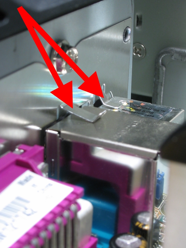 Other than that, since an IO shield is installed on the PC casing, which is grounded by the PSU, it can also protect your motherboard again static discharge from your fingers.
Additionally, an IO shield also protects your computer from tons of dust. Just imagine for a second, without an IO shield, the back of your casing will have a huge hole from which you can see inside your casing, and a lot of dust will get inside from that hole.
Not just dust, a huge hole right at the back of your casing will also invite all sorts of insects and bugs, which can get messy.
So, it’s best to install an IO shield to protect your PC.
How To Install An IO Shield
Now that you know what’s an IO shield and how it is useful, you should also learn how to install it on the PC case. The process is not difficult at all, and if you plan to build your entire rig by yourself, then installing an IO shield should be a cakewalk.
Remove The Old IO Shield
If your case has an old IO shield already installed, and your new motherboard came with its own IO shield, then you should remove the old one from the case first.
If you use the old IO shield, then chances are it will not be compatible with your new motherboard, and that can cause difficulties while screwing the motherboard in the case.
So, to remove the old IO shield, simply press it gently with your fingers from outside the case. You will hear a few clicking sounds and that means the Ield is coming out. If needed, you can apply more pressure and it will finally fall down inside the case.
Find The Right Orientation And Bend The Prongs
Here is how to find the correct combination, while installing an IO Shield on Motherboard – Image Captured by Nauman/Tech5Gamers.
Before installing the new IO shield, it is best to align it correctly with the motherboard to find the right orientation. That’s because you might end up installing the IO shield upside down, which simply will not work.
So, first, bring out the motherboard, and precisely align the IO shield with the ports. Make sure every port cut-out is aligned perfectly with its respective port, and not a single port is blocked from the IO shield, this way you will know the right orientation of the IO shield.
You might also notice that there are prongs around the port cut-outs. In order to protect the motherboard from static discharge, these prongs touch the ports to ground it. That’s why it is best to bend the prongs as well before installing the IO shield to the case.
While keeping the IO shield and the motherboard aligned, push forward the motherboard so the ports come out of the IO shield’s port cut-outs. After that, bend the prongs so that they are in contact with the ports. You will notice that the bigger prongs are touching the top of the ports, while the smaller ones are simply touching the ports.
Once done, you can move ahead and start installing the IO shield on the case.
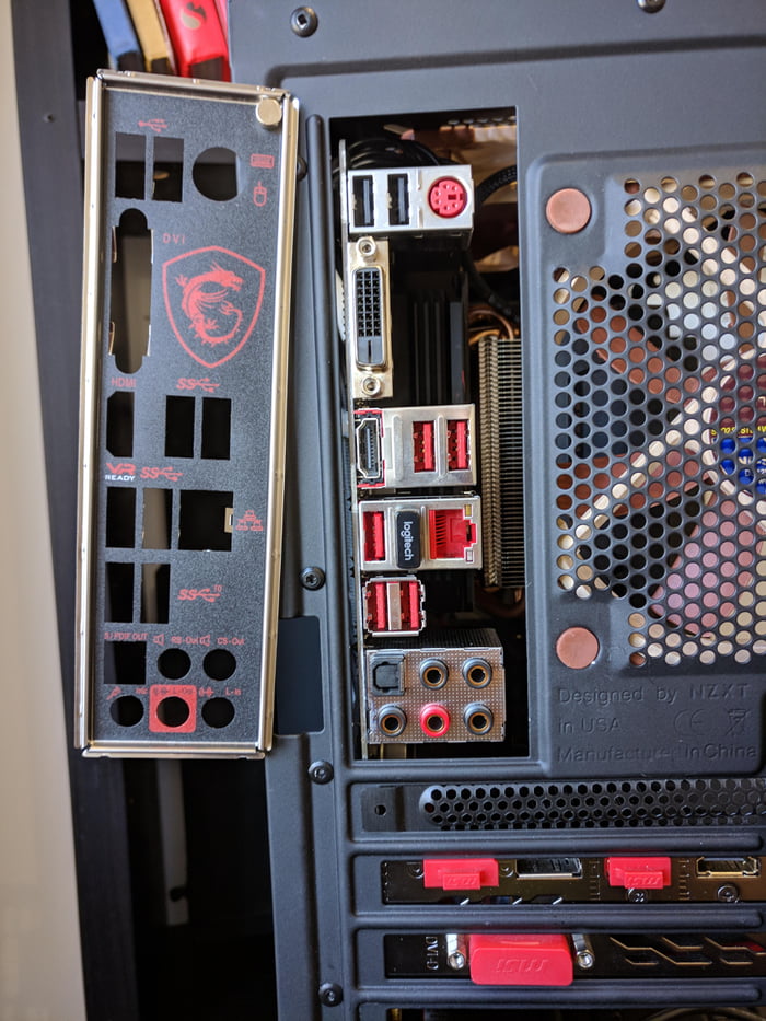
Install The IO Shield
Image Credits Robtech
To install the IO shield:
- First, make sure the case is placed on a flat surface and it will not move when you’re installing the IO shield.
- With its right orientation, place the IO shield in its place on the case from the inside.

- Once placed, you need to fit it correctly. So, gently push the shield by applying equal force to each corner one by one.
- You will hear lots of clicking noises, that’s the sound of the IO shield sitting in its place.
You might notice that the entire installation process was not difficult at all. In fact, compared to the rest of the build, the IO shield is one of the easiest parts to install. However, once it is in its place, you need to make sure it is installed correctly.
IO Shield Bracket
Notice that there are little metal bumps around the entire IO shield. If installed correctly, these bumps will be visible from inside the case. On top of that, you can also apply just a little force on the IO shield to try to move it. If it wiggles, then it means it is not installed correctly.
Make sure the IO shield is sturdy when in place, because otherwise, the motherboard ports will not align perfectly with their respective cut-outs.
What To Do When IO Shield Is Not Installed Correctly
If there is not enough room to work with, then you might find it difficult to install the IO shield. In such cases, it’s best to remove the exhaust fan on the back of the casing. This way, you will have more space to push the IO shield into its place correctly.
To remove the rear exhaust fan on the casing, all you have to do is unscrew it and it will come out on its own.
Similarly, after installation, if you find that the IO shield is wiggling a lot, then:
- Place the case down, so that the IO shield lines up with the table.
- Next, put the motherboard inside the case and align its ports with the port cut-outs on the IO shield.
- Gently push the motherboard to bring the ports out of their respective cut-outs. Bend the prongs again if needed to make sure they are touching the ports.
- Finally, start screwing the motherboard to install it in the motherboard.
After following these steps, you will notice that the IO shield does not move around anymore.
How Important Is An IO Shield On Motherboard
A prebuilt PC with dust buildup
You may wonder how important is an IO shield, and what could go wrong if you don’t install one on your PC. Well, other than the basic protection against EMI and static discharges that can potentially fry your motherboard or at least its ports, the lack of an IO shield also exposes your motherboard to a ton of dust.
Over time, dust can build up over your motherboard, and thus it will begin to retain heat that can cause overheating problems. In the long run, this can significantly reduce your motherboard’s lifespan.
On the other hand, to prevent this, you will have to clean your PC a lot. Granted it is a good thing to regularly maintain and clean your PC, but the lack of an IO shield will increase the job to quite an extent.
Overall, having a huge hole on the back of your casing is never a good idea, other than dust, it will also allow moisture and humid air to get in. So, when building your rig, it is highly recommended that you install an IO shield.
Summary
An IO shield is a metal plate that comes with your motherboard. It has port cut-outs so it can align with the motherboard perfectly. It protects the motherboard against EMI that might come from external components, and against your finger’s static discharge
On top of that, the IO shield also plays an important role in blocking any dust or moist air from getting into your PC.
Installing an IO shield is not difficult at all. You just have to do is find the right orientation, and then place it in the hole by pushing it.
FAQs
Where can I get an IO shield?
Usually, every motherboard comes with its own IO shield. However, if you have lost yours, or if yours didn’t ship with one, then you can simply order it from eBay. It shouldn’t cost above $10.
How should I mount a motherboard with a pre-installed IO shield?
If your case comes with a pre-installed IO shield, then check if it’s compatible with the motherboard you’re using. If it is, then simply screw in the motherboard, otherwise, take out the pre-installed IO shield and install your new IO shield.
Also Read: HDMI On Motherboard Not Working [SOLVED]
Was our article helpful? ??
Thank you! Please share your positive feedback. ?
?
How could we improve this post? Please Help us. ?
Electrical boards: Bulkhead of ABB AT/U board plastrons. Modules CombiLine – CS-CS.Net: Electroshaman’s Laboratory
Bulkhead of U63 shield filling on EDF profiles
So, we continue to finish master classes and lessons on the AT/U series of shields and the CombiLine system. For those who found this post through a search, I advise you to look at the latest post about the EDF / WR system and take a look at the new post about the AT / U series shields. Today we will do what the one who started working with the AT / U series of shields professionally does — shake up the stuffing of the shields to suit their tasks. When is it necessary? And when you suddenly need to place non-standard equipment in the shield. Namely: infernal copper bars to make ASU on them, some kind of controller on the circuit board, a leakage protection unit or drivers for LED strips or lamps.
The first thing that comes to mind is to arm yourself with screws and nuts and start cutting or sawing all sorts of standard DIN rails in the shield. But it’s handy if you need to make one minimal change to the shield. Well, for example, cut down one rail, screw the PE bus there, and close the plastron in this place with a plug. But when you get to a serious shield, albeit a small one, you need a different approach!
And here it is time for us to remember that all these boards are built on a system of EDF profiles and that they are assembled on green racks — the youngest part of a full-fledged EDF / WR system! What does it mean? This means that we have the opportunity to use components from a large system (on red racks) in these panels. That is, we can buy some kind of blank plastron separately and stick it instead of a plastron with DIN rails in order to cram non-standard components onto this plastron (for example, buttons and a display from some block on a microcontroller).
But at the same time, we’re in for a bit of trouble: the standard shield from the factory already has its own plastrons and stuffing. And if we remake something there, then we will either have to completely throw out the filling of such a shield, or adapt to its configuration. For example, the AT52 shield contains one large plastron 2×5 rails from the factory. And if we want to change something in this shield, then we will have to throw out the entire plastron. But the AT62 shield already contains two plastrons: 2×4 rails + 2×2 rails. And if we just need to stick a mounting panel for low current into this shield, it can be inserted instead of a 2×2 rail plastron without touching the regular 2×4 rail plastron. That is, here you will have to think hard and choose between the options “Let’s throw out the entire shield” and “We will select such a shield so that we can use part of the filling.” And these shields will always be large, because small shields like AT42 also consist of one solid plastron.
The second question that needs to be decided is what to do with the height of the rails: leave the green posts and low rails, or transfer the entire shield to red posts and high rails? Here the logic and decision also depends on how much of the shield we are shaking up. If we add a small mounting panel, then it is logical to leave everything on the green racks and reorder them for mounting. And if we shake up the shield almost completely (for example, with the AT52 from the example), then we can transfer it to red racks. And now I will tell you about how I shook the stuffing for the U63 shield in order to stick the shield components for the OWEN PLC there.
So we have shield U63. We are very lucky: it consists, as it were, of two shields, assembled together: 62 + 61. In this case, we have a bunch of separate plastrons that we can combine.
Initial switchboard configuration U63
For a PLC-based switchboard, I needed to get a complex design, which I drew and printed out for myself. For the PLC, I had to put an MBM212 mounting plate in the shield, for all sorts of relays and terminals — MBK modules, in which the DIN rail goes lower and thanks to this nothing sticks out above the shield plastrons.
Shield configuration to get
Let’s remove the plastrons and see what we have. Of course, we see thin rails, low green pillars and an additional EDF profile for rigidity.
Original shield frames before conversion
Here’s what it looks like up close:
EDF green post and 7.5mm DIN rail
What are we going to do? And in this case, it turned out that we would have so many CombiLine modules that it was easier to switch to red racks and high rails at once than to try to combine something with the old shield. In this case, I only needed to order a couple of packs of red racks and four high DIN rails, and, well, CombiLine modules. And since the shield was quite serious, here it was possible not to count money to the penny, but simply to do it the way it was necessary.
In the post about CombiLine EDF/WR system, I mentioned CombiLine modules. Now I have the opportunity to show them live and tell a little about each of them. Modules are supplied in flat boxes, which are very convenient for warehouse storage:
CombiLine modules for our switchboard conversion
On the side of the module is its article number and model. I have MBG102 modules here — this is a 1×2 panel DIN-rail module, MBK107 is a module with rails for 1×2 panel terminals, and at the bottom there is an MBM212 module with a 2×2 rail circuit board.
Miscellaneous designations of CombiLine modules
First we will work with the small half of the shield. Here I need to place a pair of DIN rails with automatic switches in the middle of it, and rails for terminals on top and bottom. The standard configuration from the factory does not suit me at all, so I will completely disassemble and redo it.
Original switchboard frame on EDF before conversion
DIN rail module for MBG (MBG102) . Included with it we have a plastron, red racks, the DIN rails themselves and all the necessary screws for mounting on EDF / WR profiles.
MBG102 module internals
DIN rail module for MBK terminals (on depth adjusters) — MBK107 . Here we already have a deaf plastron in the kit, the depth regulators themselves, special shortened DIN rails and all the same screws for fastening.
Internal filling of the MBK107 module
First of all, for the photo, I tried on how everything should be combined with one of the sides of the future panel. So, let’s try on the MBK module in its place — in the upper part of the panel. Plastron, of course, we get up as it should — in the general row.
It is necessary to replace the conventional plastron with the MBK107 module
But there will be problems with the depth regulators. Remember the red and green colors of the system? Here is what is red — it is laid under cabinets with a depth of 200 mm or more (more precisely, from 250) and should not normally be inserted into cabinets on green racks.
Here is the depth adjuster ZW39P2 (or ZW59P2 ). Such regulators can be ordered separately if you need them for some reason. But usually this is not necessary, because with all the modules where they are used (mounting panels, terminal rails) they are included, as I already showed above in the pictures. To adjust the depth, you need to unscrew the middle screw (not completely, just loosen it) and you can move the vertical piece of iron. There are divisions on it (it will be seen in neighboring photos), according to which you can even set all the regulators to the desired position in advance so as not to mess around with them in the shield in place.
Depth adjusters ZW39P2 / ZW59P2
The depth adjuster has a tricky feature — a metal plate. If it is thrown out of it, then the electrical connection of the regulator with the EDF profile is broken, and the DIN rail or circuit board that it holds will be completely decoupled from the potential of the main profile. That is why I wrote that I do not quite understand our GOST, which prohibits doing this and requires that all parts of the shield be either completely isolated or connected to PE.
Switching off the electrical connection of the controller with the EDF profile
And this feature is set by default so that, for example, different PE potentials can be made at different terminals. Let’s say some kind of power ground on some rails, and a signal ground for sensors on other rails.
We apply our depth adjuster to the EDF profile and understand that its upper part will not be covered by the plastron in AT/U shields. I deliberately left the green rack, because we may need CombiLine modules with such rails in boards assembled completely on green racks. If someone thinks that you can just lower the regulator lower, then figs to him — the regulator will almost immediately hit the bottom of the shield.
Installation of the ZW depth adjuster in the shield on the EDF profile
See what it looks like under the plastron. The lower tail of the regulator (red plastic) also protrudes so much that even it itself rests against the body (bottom) of the shield.
The ZW depth adjuster is not suitable for the board with green posts
But there is a way out! TO SAW! Yes, this smacks a little of kulibinism, but kulibinism is not unique for each shield, but completely typical — this operation can be performed accurately and technologically. Bad kulibinism is when for each shield we will do something non-standard, such that it cannot be exactly repeated and typed into a standard operation.
Since the depth regulator will hardly be used in small shields (there it can be adjusted literally by 10 mm), you can cut down its piece of iron almost to the root:
ZW depth regulator must be filed in height one major division below the «0» position.
Marking the adjusters for filing
The plastic holder also needs to be filed. You need to cut it almost to the root — at the end of the plastic recess, like this:
Marking the regulators for sawing
I saw the holders with a severely small grinder. After that, I process the plastic with a file from chips and welds and get the finished product:
Filed ZW depth regulators and their fasteners
Then I assemble the regulators again, and they are ready for use in shallow depth shields.
Depth adjusters assembled and ready to be installed in the panel
It can be considered that the adjuster lowers the DIN rail to a depth of about 18. .20 mm:
Useful depth of the rail for the terminal blocks of the MBK module
Therefore, if you get confused with a page from the catalog, then in principle you can calculate the useful depth that we will get when using regulators.
Dimensions of EDF profiles and DIN rails from catalog
Let’s try? I will round all the numbers in advance into a smaller margin, so that someone who reads the post has pre-insured options and does not break off with an extra millimeter of height.
From the top edge of the EDF profile to the bottom of the board we have about 30 (33) mm. The thickness of the rail in the standard shield is 7 (7.5) mm. From the top edge of the rail to the plastron we have 48 mm. That is, 30 + 7 + 48 = we have about 85 mm to the bottom of the shield. The depth regulator grabs itself about 15 mm in height. The total useful depth of the regulator will be about 70 mm (for the circuit board).
But we forgot at the red counters! If we switch to red racks, then the plastron rises another 7. 5 mm. Therefore, with red posts, the useful depth of the regulator will be about 77 mm (for the circuit board).
In the meantime, I fixed the first DIN rail in place and put a couple of CR-P relays on it for testing.
Testing the rail on the CR-P relay
My task was to sink the relays so that the tail of the latch does not stick out from under the plastron and does not spoil the view of the shield:
Here’s what I got under the plastron. Everything was perfectly drowned and there was even a little more free space on top of the relays.
Relays are placed on the rail so that they do not interfere with closing the plastron
Now we will arm ourselves with rails, filed with regulators, racks and everything necessary and completely shake up our entire half of the shield.
Everything you need to assemble the EDF panel for the new configuration
Since we are throwing everything out of it completely, we will be left with two bare EDF profiles. What to do to keep them rigid and the correct distance between them to assemble the filling? In this case, I take a couple of DIN rails and twist them along the edges of the profile to any place. Later, I either remove these rails or rearrange them in their places if they are needed for assembly.
Leave the DIN rails on the edges to stiffen
Insert the racks in place. Now red. The fotik from their color stomps like hell =)
Installing new red racks
I always insert extreme racks — you can’t go wrong with them.
We installed two racks for the plastron
And then I take the desired plastron and try it on the place where other racks should be inserted.
We put on the plastron to understand where the next racks should be placed
We get the following construction. Racks for the adjacent plastron will be inserted into the adjacent holes, there will be no need to try them on.
Installed all the necessary racks
Here’s what I got. At the same time, the panel itself has so far been assembled only on temporary rails.
We install all the racks by analogy
To maintain the rigidity of the panel, I will start installing regular thick rails (for red racks) from the middle of the panel, where I use them:
Plastron and DIN rails of the MBG module
The position of the rail can also be tried on directly through the plastron. We lay the plastron on the racks and move the rail under it so that it visually stands in the center of the plastron cutout. Since the rail has special protrusions for fixing on the profiles, you can simply put it on this profile — it will not go anywhere from it.
Fitting of DIN rails for plastron MBG
After that, we just have to press the rail lightly by hand and screw it cleanly to the profile with screws.
DIN rails tried on and ready to be screwed on
This is the panel I ended up with!
The whole EDF panel put together
And immediately ATTENTION! DIN-Rails for terminal blocks are cut off one module at the edges! That is, this rail should not be considered a rail for 12 modules, but a rail for 10 modules! Below in the photo, by some miracle, I got 12 pieces of relays of the CR-P series, but this may not work with automatic machines or a conventional module!
Testing the installation of all relays on the rail MBK
Look carefully! You see, on an ordinary rail, supported by a limiter, there is a two-module wide difautomat? I attached a piece of the ruler so that it almost rested on the side edge of the depth control — and I lost almost the whole module!
MBK module scoops up a whole DIN module around the edges
Now let’s work on the big half of the shield. Here I need to stick the MBM212 mounting plate into the lower part of the shield, and on the upper part, replace all the rails with thick ones.
Large EDF frame for conversion
MBM mounting plate module (MBM212) . It contains in the kit depth regulators (in the photo below they have not yet been filed), a blind plastron, racks and screws. The mounting plate itself is made of a strong metal sheet that you can fucking bend and drill. Be careful — the usable mounting area is not as large as it seems. The photo shows the edges of the metal with which it is attached to the depth controls. Here we can conditionally assume that the useful area of the installation is everything except for these edges for fastening.
MBM212 Mounting Plate Module
This is what we should end up with. Here I leave the standard plastron from the shield and add a montage.
Trying on the plastron from the MBM212 module
This time I started from the top of the shield to immediately keep the profiles rigid. I change racks to red ones.
Change the posts like
After that, I add one DIN rail to the bottom of the shield for strength, and the top rails just change to thick ones, which are for the red posts.
Leave one DIN rail for rigidity
Medium profile, which adds rigidity to thin DIN rails, I throw away in this case. If I wanted to get confused with it, then I would have to either cut it with a grinder shorter, which I don’t like (because you can’t get it anywhere else later), or order a shorter EDF profile. But the thick slats are purpose-built to handle double-width loads.
Mounting plate from MBM212
Fitting the depth adjusters for the mounting plate. If we are talking about the montage, then all the montages are invented so cleverly that you can not try anything there, and you can’t go wrong if you put the regulators close to the racks.
ZW Depth Adjuster Mount for MBM212 Mounting Plate
After that, I got two halves of one shield, assembled as I needed.
All parts of the new frame are fully assembled
But let’s think. What will happen now if I start collecting this shield? After all, the halves are not connected in any way! How will the customer remove the frame of the shield when he needs to brick up his body into the wall? Do you really have to somehow assemble the shield in halves and connect it with terminals? Or will the shield halves hang on the wires, which is of course bad?
Well, of course, there is a way out, and even such a bad idea is thought out. For such cases, there are ZX66P4 connectors that allow you to connect two EDF / WR profiles side by side, like this: ||. These connectors are sold in a pack of four, all screws are included.
EDF profile connector ZX66P4
Even without a shield, the connector automatically maintains the exact distance between the profiles. All we need (I showed it on old rails) is to find a convenient place for it (so that it does not interfere with DIN rails) and screw it onto the profiles.
Trying on the ZX66P4 connector
And there is one more little joke: the connector is also created for the “red” system, because there, due to the higher rail, it will not interfere with the module. In green racks, the fastening screws of this connector can sometimes fall right under the machines and get in the way.
Installing the ZX66P4 connector
After that, we can put something for the test and check out how interesting everything turned out and looks. Here are the adjacent rails of the two halves of the shield. In principle, if it turned out that these rails would be at the same height in height, then I could additionally order three-panel DIN rails and this would also add structural rigidity. But in fact, you don’t need to bother so much — the ZX66P4 connector gives the necessary rigidity even on a WR frame.
Neighboring DIN-rails with different configurations of shield frames
Well, all that remains for me is to try on the OWEN PLC (and this shield is just from the post about this PLC) and fix it on the mounting panel.
Preparing to install the OWEN 110 PLC on the mounting plate
At first I thought that I would fix the OWEN on the mounting plate directly with screws. But then I decided that if one of the modules needed to be replaced, it would be difficult to unscrew the screws in a shield full of wires. And I got confused with ordinary DIN rails.
OWEN 110 PLC installed on the panel mounting plate
That’s what I got! The controller stood up perfectly and there is a lot of free space above it (photo without DIN rails)!
Example of closing the PLC with a shield plastron
Here you can clearly see that the controller is on a mounting plate without a DIN rail. Let’s calculate what useful depth we got? The height of such a controller is 73 mm. The height of the DIN Rail I put this controller on is 7.5mm. That is, as a result, the installation provided us with a useful height of at least 73 + 7.5 = 80.5 mm.
Example of closing the PLC with a shield plastron
In short, if you have a non-standard controller up to 85. .90 mm high, then you can stick it into the AT / U series shield if you put a mounting panel there. And this is good, because it is not always necessary to buy a large cabinet for a small controller.
Well, I myself have to come to grips with assembling the shield on this PLC, which I wrote about earlier.
The panel and all its components are completely ready for installation and assembly
If you are building a system based on a bare EDF/WR profile without a casing (see examples of such pieces here), then you will also need to file the depth adjusters. Well, if you are assembling a cabinet of great depth (B series or TwinLine), then you do not need to file anything.
4.b) Boss Walkthrough — Warframe briefe guide 32.0.13
Return to TOC
Back 4. All planet bosses
-
Captain Vor (Mercury) — catch between teleportations, shoot in the stomach — in a clot of energy.
 3 stages, between which it becomes invulnerable and summons Grineer soldiers.
 -
Advisor Wei Hek (Earth) — ignore the flying form and run to the final location. There, in the first phase of the battle, shoot at the opening face. In the second phase, just shoot at the boss, do not allow to recover from the absorption of ordinary soldiers.
-
Lieutenant Lech Creel (Mars) — shoot from the back at the tubes, after shooting them into the reactor on the back
-
Sergeant (Phobos) — just damage
-
Lech Creel+Vor (Ceres) — similar to single versions
-
General Sargas Rook (Saturn) — shoot in three phases at luminous details
-
Sprague — Ven’Kra Tel — shoot at backpacks, catch on fades after attacks
-
Kela de Thaym (Eris) — shoot at 4 wall targets from the place of special circles, after closing all — meet the boss.
 Periodically dodge orbital shots. It is very convenient to use **Ignis** or stream weapons to disable targets. The boss’s ult works well Misa
 -
Till Regor (Uranus) — 1st phase — catch after teleportation, kill Grineer madmen, 2nd phase (after flooding the lower tier) — catch after teleportation, kill Grineer madmen, 3rd phase (after flooding the middle tier) — catch after teleportation . Good help Misa .
-
Wolf — armored and high health — need weapons with good damage and warframes with high damage or damage buff.
-
Tusk Shakers — armored, stomping in series, jumping, firing missiles. Kill — shoot off the caps on the legs and hit the green lights (4 pcs). Operator beam especially with a piercing prism/backing or aoe gives more damage. Can be slowed by ability Time Blast (default key is E in Operator Mode ), Zenurik Focus school Zenurik wiki icon.
 Shaker can’t deal 3 hit damage to Titania when she’s above the ground in flight mode, but can still shoot at her, but you can throw razors to keep him occupied. Polarization Mag removes a lot of armor from him. Sarpa with radiation damage does more damage than all other weapons
-
Alad V (Jupiter) — drop Zanuku while Alad raises Zanuku — hit Alad
-
Zanuka ( Hunter Zanuka ) — just damage
-
Ambulas (Pluto) — need to reprogram 5 prototypes of **Ambulas** — very strong — after damage, you need to hack. Don’t let the drones repair them.
-
Sergeant (Phobos) — just damage
-
Jackal (Venus) — knock out a limb, after falling finish off with parazon , repeat 3 more times (do not forget to dodge the UFO attack)
-
Pack of hyenas (Neptune) (*4) — just damage
-
Raptor (Europe) — wait for the exit, knock out, pick up the bomb from the corpse and throw it into the Raptor exit shaft — repeat 3 times
-
Ropalolyst (Jupiter) — remove health, move to the column (one of three), wait until Rapololyst hits it (glows purple), then jump to Rapololyst and press the action key (by default “X” ”), by controlling Rapololist to ram this column.
 Auto move to the center, shooting mobs, repeat actions with other columns.
 -
Lynx — mini-boss — destroy 4 drones until the boss calls for new ones to beat Lynx
-
Profit Sphere (Venus) — stage 1 — remove the shield with the type of damage that is on the forehead of the sphere, it is possible to change the type of damage through the operator’s shot. ** stage 2 ** — shooting capsules. ** Stage 3 ** — shoot 4 limbs and the carcass itself with an arch weapon with a gyromag. Collect loot and run away before the explosion.
-
Exploitation Sphere (Venus) — Stage 1 — shoot one of the cooling blocks on the Sphere. 2 stage in the cave collect heat cells and throw them into the cooling blocks of the Sphere, after 2 hits in the same block it can be shot. After shooting all (4 pieces, 2 from each side), move to the surface.
 ** stage 3 ** — shooting spiders with cooling blocks at a distance, preventing them from approaching the Sphere. Raise cells and charge them from faults (yellow). When the Sphere overheats, move to it and there will be a finishing cutscene, repeat 3 times
-
Lefantis (Orokin Ruins) — 1 and 2 phase shoot 3 heads: 1 (mouth) — in the mouth when opening, 2 (cobra) in the hood when opening, 3 (mower) — in the mouth and face upon impact and after impact
-
Forid (invasion of the infected) — just damage
-
Mutalist Alad V — substitute for the capture of an ally, at this moment beat Alad ( Misa demolishes per second)
-
Infected Misa —
-
Juggernaut (Behemoth) — dodge ram attacks, shoot in the stomach or back (catch the moment of attack)
-
Golem Jordas — go to the tail and shoot at the engine.
 Corrosion auras and corrosion damage are needed.
 -
Emissary (Prelate Zealoid) — Stage 1 — demolish half of health. Phase 2 — move on to kill the shadow, pick up the lantern, kill the Emissary in the light of the lantern, the lantern goes out — run for a new one.
-
Plague Star (Lefantis in the Eidalon Valley) — we complete the task from Konzu , we reach the crash site with the drone, we meet Lefantis, we destroy the waves of the infected, we repeat. Titania , 2 Reno , Nova — a good party to pass (advice from Sheo from the chat).
Sentient — they adapt to damage, which means that after being shot or hit with conventional weapons, VRs become resistant to damage by this type of damage. To remove the resistances, you need to switch to the operator and shoot the operator to remove the resistances, after which you can return to the Warframe and continue to hit with the weapons or abilities of the Warframe. If stability occurs again, repeat the procedure by the operator … and so on until victory.
Nikhil — Nikhil has 3 hits: 1) vertically with a sword — breaks platforms. 2) horizontally — immediately kills you. You need to jump in time. 3) shoots fragments — you need to dodge (it’s better to wait for the shot on the platform and move a couple of meters away at the time of the shot). To defeat Nikhil , you need to pick up glass shards that Nikhil shoots at you and shoot these shards at Crystals that are hanging in the air. When you get into the crystal with the required evidence (by quest) from Nikhil invulnerability will drop, after which you will need to shoot at Nikhil himself. And so 3 times: dodge, shoot at the crystals, shoot at Nikhil . Well, do not forget to bounce from horizontal strikes and jump to other platforms dodging vertical strikes.
1. Take on a mission a weapon that does good damage to shields.
2. We charge the glaive — 3 yellow (gold) stars near the sight. To charge the glaive, you need to kill the flyer with a weapon (primary, secondary, glaive), after killing it, it will become lvl 50+, after that we throw a glaive and explosions at it.
3. Start damaging Proteus . Remove 1 strip (division). She begins to ult (roll back time). At this moment, you need to throw a glaive at her and blow it up. We equip the glaive, press E and in flight one more (E) time (undermine). Thus, we bring down the ult. And Protea does not roll back his life (HP).
-
We repeat everything from 2 to 3 points. Until he dies!
-
Eidolon Guide by Reifnir
-
Eidolon Teralyst — remove the shield by the operator (you need an amplifier in assembly 7-7-7 (see guides)), after removing the shields, shoot at the limbs (according to the so-called Synovia — growths, thickenings).
 Before shooting off the limbs, you need to have 2 lures (flying, uninitiated grinier robots that appear at night at the points of grinier camps), feed lures a couple of small BP. If you play without lures, the Teralyst will run away from you to a new place after each ejected limb (and you need to shoot 4 of them). After shooting off the limb, a shield will appear again — shoot the operator with shots …. after the fourth ejection of the limb, you need to sell Eidalon again, after which he will try to escape (but you have 2 charged lure ) — done, you caught him!
 -
Eidolon Gantulyst — after killing/capturing a Teralyst, a Radiant Shard will remain, which must be placed on an island in a large lake on an altar (must be done by all party members) — this will summon a Gantulyst, then do the same as with the Teralyst.
-
Eidolon Hydroleaf — see above. only baits need 3 pieces (he has 4 arms, 6 limbs in total)
-
Hunters
-
Stalker/Shadow Stalker — before appearing, choose a large room, keep a distance of 5-10 meters, constantly move around Stalker , damage, periodically remove the adaptation of Stalker to these types of damage with the operator’s beam.