How IDE Controllers Work | HowStuffWorks
No matter what you do with your computer, storage is an important part of your system. In fact, most personal computers have one or more of the following storage devices:
Usually, these devices connect to the computer through an Integrated Drive Electronics (IDE) interface. Essentially, an IDE interface is a standard way for a storage device to connect to a computer. IDE is actually not the true technical name for the interface standard. The original name, AT Attachment (ATA), signified that the interface was initially developed for the IBM AT computer. In this article, you will learn about the evolution of IDE/ATA, what the pinouts are and exactly what «slave» and «master» mean in IDE.
Advertisement
Contents
- IDE Evolution
- Controllers, Drives, Host Adapters
- Cable Key
- Masters and Slaves
Controllers, Drives, Host Adapters
Most motherboards come with an IDE interface. This interface is often referred to as an IDE controller, which is incorrect. The interface is actually a host adapter, meaning that it provides a way to connect a complete device to the computer (host). The actual controller is on a circuit board attached to the hard drive. That’s the reason it’s called Integrated Drive Electronics in the first place!
While the IDE interface was originally developed for connecting hard drives, it has evolved into the universal interface for connecting internal floppy drives, CD-ROM drives and even some tape backup drives. Although it is very popular for internal drives, IDE is rarely used for attaching an external device.
Advertisement
There are several variations of ATA, each one adding to the previous standard and maintaining backward compatibility.
The standards include:
ATA-1 — The original specification that Compaq included in the Deskpro 386. It instituted the use of a master/slave configuration. ATA-1 was based on a subset of the standard ISA 96-pin connector that uses either 40 or 44 pin connectors and cables. In the 44-pin version, the extra four pins are used to supply power to a drive that doesn’t have a separate power connector. Additionally, ATA-1 provides signal timing for direct memory access (DMA) and programmed input/output (PIO) functions. DMA means that the drive sends information directly to memory, while PIO means that the computer’s central processing unit (CPU) manages the information transfer. ATA-1 is more commonly known as IDE.
ATA-2 — DMA was fully implemented beginning with the ATA-2 version. Standard DMA transfer rates increased from 4.16 megabytes per second (MBps) in ATA-1 to as many as 16.67 MBps. ATA-2 provides power management, PCMCIA card support and removable device support. ATA-2 is often called EIDE (Enhanced IDE), Fast ATA or Fast ATA-2. The total hard drive size supported increased to 137.4 gigabytes. ATA-2 provided standard translation methods for Cylinder Head Sector (CHS) for hard drives up to 8.4 gigabytes in size. CHS is how the system determines where the data is located on a hard drive. The reason for the big discrepancy between total hard drive size and CHS hard drive support is because of the bit sizes used by the basic input/output system (BIOS) for CHS. CHS has a fixed length for each part of the address:
- Cylinder = 10-bit, 1024
- Head = 8-bit, 256
- Sector = 6-bit, 63*
You will note that the number of sectors is 63 instead of 64. This is because a sector cannot begin with zero. Each sector holds 512 bytes. If you multiply 1,024 x 256 x 63 x 512, you will get 8,455,716,864 bytes or approximately 8.4 gigabytes. Newer BIOS versions increased the bit size for CHS, providing support for the full 137.4 gigabytes. ATA-3 — With the addition of Self-Monitoring Analysis and Reporting Technology (SMART), IDE drives were made more reliable. ATA-3 also adds password protection to access drives, providing a valuable security feature.
ATA-4 — Probably the two biggest additions to the standard in this version are Ultra DMA support and the integration of the AT Attachment Program Interface (ATAPI) standard. ATAPI provides a common interface for CD-ROM drives, tape backup drives and other removable storage devices. Before ATA-4, ATAPI was a completely separate standard. With the inclusion of ATAPI, ATA-4 immediately improved the removable media support of ATA. Ultra DMA increased the DMA transfer rate from ATA-2’s 16.67 MBps to 33.33 MBps. In addition to the existing cable that uses 40 pins and 40 conductors (wires), this version introduces a cable that has 80 conductors. The other 40 conductors are ground wires interspersed between the standard 40 conductors to improve signal quality. ATA-4 is also known as Ultra DMA, Ultra ATA and Ultra ATA/33.
ATA-5 — The major update in ATA-5 is auto detection of which cable is used: the 40-conductor or 80-conductor version. Ultra DMA is increased to 66.67 MB/sec with the use of the 80-conductor cable. ATA-5 is also called Ultra ATA/66.
Advertisement
Cable Key
IDE devices use a ribbon cable to connect to each other. Ribbon cables have all of the wires laid flat next to each other instead of bunched or wrapped together in a bundle. IDE ribbon cables have either 40 or 80 wires. There is a connector at each end of the cable and another one about two-thirds of the distance from the motherboard connector. This cable cannot exceed 18 inches (46 cm) in total length (12 inches from first to second connector, and 6 inches from second to third) to maintain signal integrity. The three connectors are typically different colors and attach to specific items:
- The blue connector attaches to the motherboard.
- The black connector attaches to the primary (master) drive.
- The grey connector attaches to the secondary (slave) drive.
Along one side of the cable is a stripe. This stripe tells you that the wire on that side is attached to Pin 1 of each connector. Wire 20 is not connected to anything. In fact, there is no pin at that position. This position is used to ensure that the cable is attached to the drive in the correct position.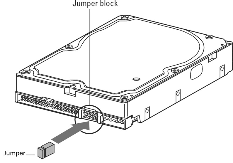 Another way that manufacturers make sure the cable is not reversed is by using a cable key. The cable key is a small, plastic square on top of the connector on the ribbon cable that fits into a notch on the connector of the device. This allows the cable to attach in only one position.
Advertisement
Pin Numbers and Descriptions
- Reset
- Ground
- Data Bit 7
- Data Bit 8
- Data Bit 6
- Data Bit 9
- Data Bit 5
- Data Bit 10
- Data Bit 4
- Data Bit 11
- Data Bit 3
- Data Bit 12
- Data Bit 2
- Data Bit 13
- Data Bit 1
- Data Bit 14
- Data Bit 0
- Data Bit 15
- Ground
- Cable Key (pin missing)
- DRQ 3
- Ground
- -IOW
- Ground
- -IOR
- Ground
- I/O Channel Ready
- SPSYNC: Cable Select
- -DACK 3
- Ground
- RQ 14
- -IOCS 16
- Address Bit 1
- -PDIAG
- Address Bit 0
- Address Bit 2
- -CS1FX
- -CS3FX
- -DA/SP
- Ground
- +5 Volts (Logic) (Optional)
- +5 Volts (Motor) (Optional)
- Ground (Optional)
- -Type (Optional)
Note that the last four pins are only used by devices that require power through the ribbon cable.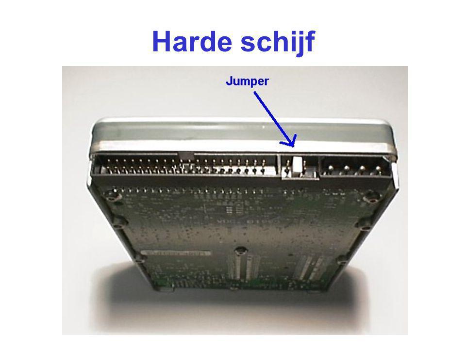 Typically, such devices are hard drives that are too small (for example, 2.5 inches) to need a separate power supply.
Advertisement
Masters and Slaves
A single IDE interface can support two devices. Most motherboards come with dual IDE interfaces (primary and secondary) for up to four IDE devices. Because the controller is integrated with the drive, there is no overall controller to decide which device is currently communicating with the computer. This is not a problem as long as each device is on a separate interface, but adding support for a second drive on the same cable took some ingenuity.
To allow for two drives on the same cable, IDE uses a special configuration called master and slave. This configuration allows one drive’s controller to tell the other drive when it can transfer data to or from the computer. What happens is the slave drive makes a request to the master drive, which checks to see if it is currently communicating with the computer.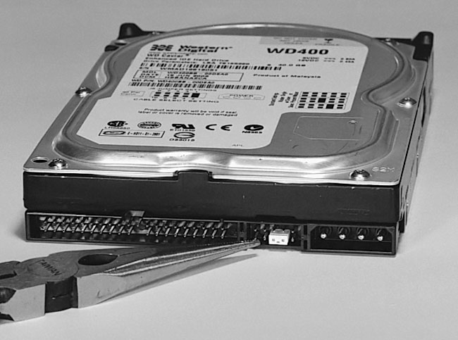 If the master drive is idle, it tells the slave drive to go ahead. If the master drive is communicating with the computer, it tells the slave drive to wait and then informs it when it can go ahead.
Advertisement
The computer determines if there is a second (slave) drive attached through the use of Pin 39 on the connector. Pin 39 carries a special signal, called Drive Active/Slave Present (DASP), that checks to see if a slave drive is present.
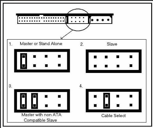
Although it will work in either position, it is recommended that the master drive is attached to the connector at the very end of the IDE ribbon cable. Then, a jumper on the back of the drive next to the IDE connector must be set in the correct position to identify the drive as the master drive. The slave drive must have either the master jumper removed or a special slave jumper set, depending on the drive. Also, the slave drive is attached to the connector near the middle of the IDE ribbon cable. Each drive’s controller board looks at the jumper setting to determine whether it is a slave or a master. This tells them how to perform. Every drive is capable of being either slave or master when you receive it from the manufacturer. If only one drive is installed, it should always be the master drive.
Many drives feature an option called Cable Select (CS). With the correct type of IDE ribbon cable, these drives can be auto configured as master or slave. CS works like this: A jumper on each drive is set to the CS option. The cable itself is just like a normal IDE cable except for one difference — Pin 28 only connects to the master drive connector. When your computer is powered up, the IDE interface sends a signal along the wire for Pin 28. Only the drive attached to the master connector receives the signal. That drive then configures itself as the master drive. Since the other drive received no signal, it defaults to slave mode.
For more information, check out the links on the next page.
Advertisement
Frequently Answered Questions
How many IDE controllers can a PC motherboard support?
Most PC motherboards support two IDE controllers.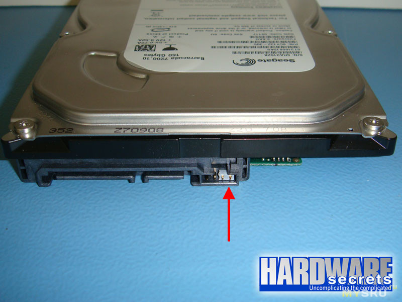
What is the IDE controller?
The IDE controller is a device that is used to connect IDE devices to a computer system. IDE devices include hard drives, optical drives, and floppy drives. The IDE controller allows these devices to be connected to the computer system via a single interface.
Lots More Information
Related HowStuffWorks Articles
More Great Links
- PCGuide: IDE/ATA Interface
- Enhanced IDE FAQ
- VIA Arena: Forums: Onboard IDE Controller Issues
- Byte: IDE Takes Off
- SCSI FAQ
Cite This!
Please copy/paste the following text to properly cite this HowStuffWorks.com article:
Jeff Tyson
«How IDE Controllers Work»
7 March 2001.
HowStuffWorks.com. <https://computer.howstuffworks.com/ide.htm>
7 July 2023
Citation
How to Identify Masters or Slaves on Hard Drives | Small Business
By David Weedmark
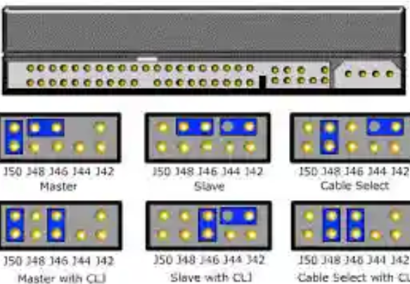
Master and slave settings on IDE hard drives are designed so you can put two drives on a single IDE cable.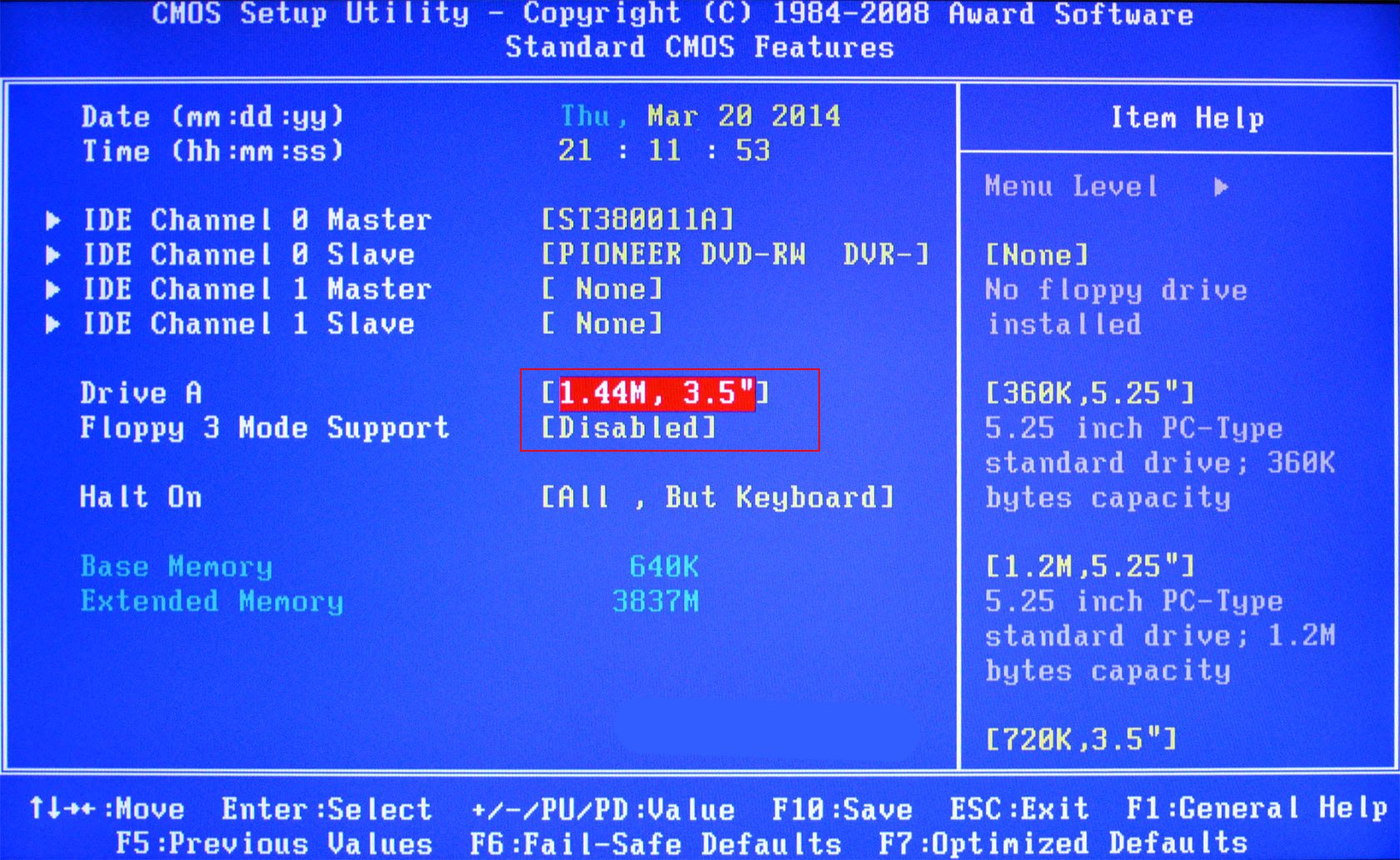 One acts as the master or main drive and the other is the slave. A hard drive’s master or slave role is determined by the position of a jumper which is placed on a series of pins on the back of the drive, usually located beside the power plug. When you look at the jumper, it looks like a small rectangular piece of plastic. Beneath this plastic is a metal connector that fits over two pins, creating a circuit between them. When you compare the jumper’s position with the pinout diagram for the hard drive, you can tell if the drive is a master or a slave.
-
Examine the stickers on the hard drives for a master/slave pinout diagram. This diagram is usually near the pins or near the hard drive serial number. If there is no sticker, visit the manufacturer’s support website to find the pinout diagram for the hard drive.
-
Locate the pins on the back of the hard drive, usually beside the power plug. The number of pins varies. Some models have eight or ten pins in two rows and others may have only three pins.
 Look for a jumper on the pins, which is a small plastic rectangle that fits over two pins, creating a circuit between them.
 -
Compare the location of the jumper with the pin settings in the diagram. One setting indicates a slave and the other indicates a master. Other jumper positions may be indicated, like a cable select setting, but these are not used in a master-slave configuration.
Examples of Pinout Configurations
-
Look for two rows of four pins on a Seagate U Series or Barracuda ATA drive located beside the power adapter. If there is not a jumper on the pins, it is a slave. If there is a jumper on pins seven and eight, which are the two on the left, the drive is a master or single drive.
-
Look for two rows of four pins on a 2.5-inch Western Digital EIDE drive. If there is no jumper on the pins, it is a master drive. If a jumper connects pins A and B, which are the two on the right, it is a slave drive.
-
Look for two rows of five pins on a 3.
 5-inch Western Digital EIDE drive. If a jumper connects pins five and six, which are the center pins on each row, it is a master. If the jumper connects pins three and four, which are the pins second to the right, it is a slave.
References
- Seagate: Jumper Settings for Seagate and Maxtor ATA Hard Drives
- WDC: Jumper Settings WD SATA and EIDE Hard Drives
Tips
- If two drives are on the same IDE cable, one is the master and the other is the slave. You only need to identify one of the drives to know the designation of the other. If you identify one as the slave, the other must be the master.
Writer Bio
A published author and professional speaker, David Weedmark has advised businesses and governments on technology, media and marketing for more than 20 years. He has taught computer science at Algonquin College, has started three successful businesses, and has written hundreds of articles for newspapers and magazines throughout Canada and the United States.
Primary IDE Master, IDE Channel 0 Master, Primary Master
Other identical option names: IDE Channel 0 Master, Primary Master.
There are several options in the BIOS for configuring hard drives and other internal drives (drives). The Primary IDE Master option is one of the most commonly used of its kind.
Article content
- How it works
- Which value should I choose?
How it works
Typically, before the advent of the SATA interface, most personal computer motherboards only supported IDE interface drives. Typically, the user could install no more than 4 drives — hard drives or CD / DVD drives. Two of them can be located on the primary IDE channel (Primary), and the other two on the secondary channel (Secondary). In each of these two pairs of drives, one drive is the Master and the other is the Slave. Thus, in total, the BIOS, as a rule, has four options for configuring drives:
- Primary IDE Master
- Primary IDE Slave
- Secondary IDE Master
- Secondary IDE Slave
Each IDE channel is a connector that connects to an IDE data cable, which in turn has three connectors.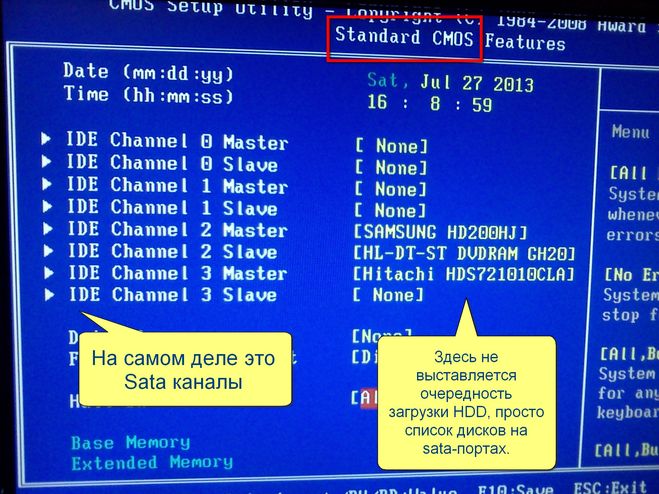 One of them is designed to connect to the IDE connector on the motherboard, the other two are for connecting drives. The choice of which category the drive will belong to — the Master or Slave category, is determined solely by the installation of jumpers on the drives, which must be carried out in accordance with the instructions attached to the drive.
In the parameter you can see a number of sub-options that can define the type of drive, its characteristics, capacity and some operating parameters.
The most important of these options is the Type option. As a rule, it can take the following values:
- Auto – drive type is determined automatically
- User — the user can set the drive type manually
- CDROM — the drive is a CD/DVD drive
- ZIP — drive is an Iomega ZIP 9 type device0014
- LS-120 — the drive is an LS-120 type device
- None — this device is not used
Also in this option, you can sometimes select a predefined type of drive, indicated by some number, for example, from 0 to 50. cylinders and sectors.
The following additional options are also often found:
- LBA Mode
- IDE HDD Block Mode or Multi-Sector Transfers
- Programmed I/O Modes
Which value should I choose?
Typically, after the drive is connected and the computer boots up, the BIOS will automatically set the drive’s Type to Auto. This means that the BIOS automatically detects all drive parameter values and does not require manual configuration.
The vast majority of IDE drives support auto tuning. The only exceptions can be very old drives, occasionally found in ancient computers, for which you may need to manually set the number of heads, cylinders and sectors.
The LBA Mode option needs some explanation. This option is to enable the addressing mode used by hard drives larger than 504 MB. If you are using a smaller hard drive, then you must disable this option. For the rest of the settings, it’s best to leave the default values.
Recommend this article to your friends:
IDE interface
Whatever SCSI proponents say, the widespread use of IDE devices today is a fait accompli. According to the smart people at Quantum, over 90% of PC-compatible personal computers are equipped with IDE hard drives. The trouble, however, is that IDE or Integrated Device Electronic is a very general concept and refers, generally speaking, to any device with an integrated controller up to an electric kettle with automatic shutdown when boiling. In an attempt to somehow specify what kind of interface is meant, so many different names have been invented that when choosing a hard drive with an IDE interface, an unprepared person may feel dizzy. Judge for yourself: there are ATA interfaces with different numbers, Fast ATA (also with numbers), Ultra ATA (also several), and, finally, EIDE! Are all these interfaces really different, which ones are compatible and which one is better? Let’s try to figure it out.
First, a little history.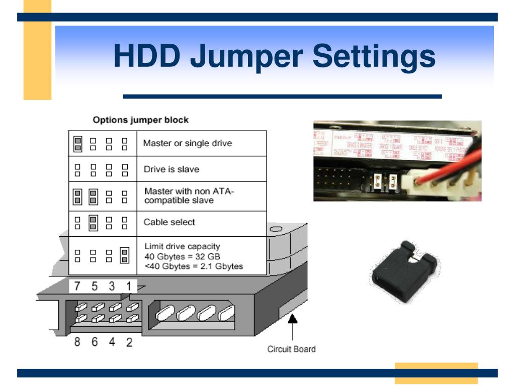 After IBM released the AT (Advanced Technology) model, Compaq and Western Digital had the idea in 1984 to embed an AT-compatible controller using the 16-bit ISA bus directly into the hard drive electronics. No sooner said than done. It turned out well: the price of a hard disk has increased insignificantly, but the cost of the entire disk subsystem has noticeably decreased. And so the ATA interface (AT Attachment — literally translated — “attachment to AT”) was born, which became widely known as IDE. Since the ISA bus in the AT model was 16-bit, the interface, of course, also turned out to be 16-bit, and this bit depth has been preserved to this day, despite subsequent improvements and additions. Soon, however, it turned out that different manufacturers managed to make discs with an ATA interface that were incompatible with each other. If such disks were installed in a master / slave pair on one IDE channel, then the disk subsystem simply did not work. To eliminate these unpleasant phenomena, the ANSI ATA specification was adopted.
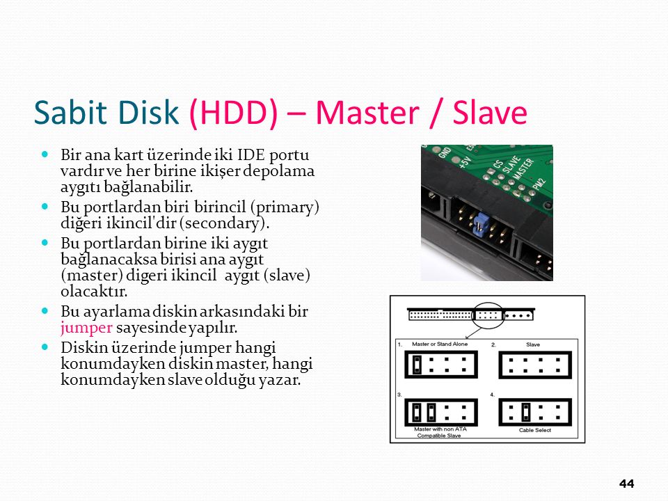 The «original» ATA interface had the following features:
- Dual hard drive support . One channel is shared between two devices configured as master and slave;
- PIO Modes . ATA includes support for PIO modes 0,1 and 2;
- DMA Modes . ATA includes support for single word DMA modes 0, 1 and 2 and multiword DMA mode 0.
The «original» ATA interface is only for connecting hard drives and does not support features such as ATAPI — an interface for connecting IDE devices other than hard drives, block mode transfer mode and LBA (logical block addressing).
The ATA standard soon ceased to meet the growing demand as newly released hard drives demanded faster data transfer rates and new features. Thus, the ATA-2 interface was born, which was soon also standardized by ANSI. While maintaining backward compatibility with the ATA standard, ATA-2 contained several new features:
- Faster PIO Modes .
 Added support for PIO modes 3 and 4 to ATA-2;
 - Faster DMA Modes . ATA-2 supports multiword DMA modes 1 and 2;
- Block Transfer . ATA-2 includes commands to allow block transfers to improve performance;
- Logical Block Addressing (LBA) . ATA-2 requires the hard drive to support the LBA transfer protocol. Of course, to use this protocol, the BIOS must also support it;
- Improved Identify Drive command . Increased the amount of information about the characteristics that the hard drive issues on system requests.
And everything would be fine, but manufacturing companies, in an effort to get another piece of the market, began to come up with beautiful names and call them names for their hard drive interfaces. In fact, the interfaces Fast ATA, Fast ATA-2 and Enhanced IDE are based on the ATA-2 standard and are nothing more than marketing terms. The only difference between them is what part of the standard and how they support it.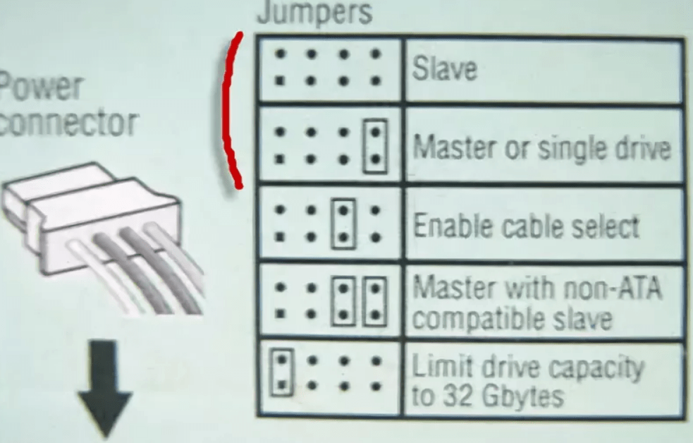
The most confusing names are Fast ATA and Fast ATA-2, which belong to Seagate and Quantum, respectively. It seems quite natural that Fast ATA is some improvement of the ATA standard, while Fast ATA-2 is based on the ATA-2 standard. But everything, alas, is not so simple. In fact, Fast ATA-2 is just another name for the ATA-2 standard, and Fast ATA differs from it only in that it does not support the fastest modes — PIO mode 4 and DMA mode 2. At the same time, both companies attack Western Digital and her EIDE standard for adding to the confusion. EIDE has its drawbacks, but more on that later.
An attempt to further develop the ATA interface was the draft ATA-3 standard, which focused on improving reliability: remained the same as at the birth of the standard;
ATA-3 was not approved as an ANSI standard, mainly because it did not introduce new data transfer modes, although SMART technology is now widely used by hard drive manufacturers.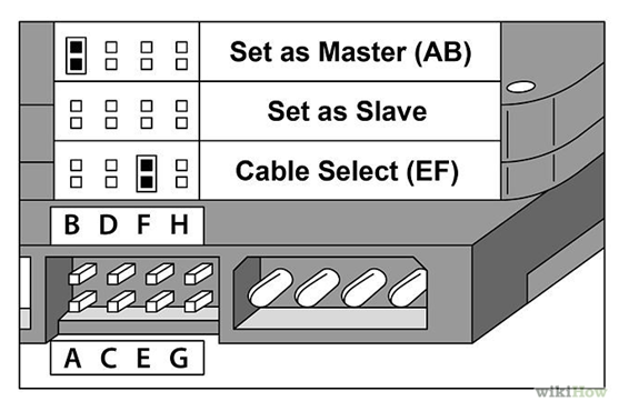
The next step in the development of the IDE/ATA interface was the Ultra ATA standard (aka Ultra DMA, aka ATA-33, aka DMA-33, sometimes called ATA-3(!)). Ultra ATA is the de facto standard for using the fastest DMA mode, mode 3, which provides a data transfer rate of 33.3 MB/s. To ensure reliable data transmission over the same cable, special error control and correction schemes are used, while maintaining backward compatibility with previous standards — ATA and ATA-2. That is, if you, having bought a hard drive with an Ultra ATA interface, suddenly find that your motherboard does not support it, do not worry — the drive will still work, although it will be slower 🙂
And finally, the latest achievement in this area is the Ultra ATA/66 interface developed by Quantum, which allows data transfer at a speed of 66MB/sec.
At the time the IDE/ATA interface was being developed, the only device that needed this interface was the hard drive, since tape drives and nascent CD-ROM drives had their own interface (many remember the days when the CD-ROM was connected through the interface on sound card). However, it soon became clear that the use of a fast and relatively simple IDE / ATA interface to connect all devices promises significant benefits, including due to its versatility. However, the IDE / ATA interface command system was designed only for hard drives, so you can’t just connect, for example, a CD-ROM to an IDE channel — it won’t work (I personally checked it when I tried to connect a CD-ROM instead of a bootable IDE drive on a 486 server Hewlett-Packard). At first, in his youth, he was at a loss: how is it that the train fits, but does not work?). I had to develop a new protocol — ATA Packet Interface or ATAPI. This protocol allows other devices to connect using a standard IDE cable and «behave» like an IDE/ATA hard drive. In fact, the ATAPI protocol is much more complicated than ATA, since data transfer takes place using the standard PIO and DMA modes, and the implementation of support for these modes depends significantly on the type of device connected. This protocol received the name packet (packet) for the reason that the device really has to send commands in groups or packets.
 However, from the user’s point of view, which is the most important thing, there is no difference between an IDE/ATA hard drive, an ATAPI CD-ROM or a ZIP drive. Modern BIOSes even support booting from ATAPI devices.
Now, as promised, let’s talk a little about EIDE. This term, coined by Western Digital, is widely used in the computer industry and is almost as widely criticized, and rightly so. One of the reasons for criticism is the fact that EIDE is not a standard, but only a marketing term, and its content changes over time. So, initially EIDE included support for PIO modes up to mode 3, then support for mode 4 was added. Another significant drawback of EIDE as a standard is the fact that its specification includes completely diverse things. Judge for yourself, EIDE currently includes:
- ATA-2 . Entirely, including the fastest modes;
- ATAPI . Whole;
- Dual IDE/ATA Host Adapters . The EIDE standard includes support for two IDE/ATA hosts, which allows up to 4 IDE/ATA/ATAPI devices to be used simultaneously.

Now let’s see what the phrase «EIDE hard drive» means. Since it absolutely does not need to support ATAPI, and it is not able to support two IDE channels, it all comes down to a much more modest one: “a hard drive with an ATA-2 interface”. In principle, the idea was good — to create a standard covering the BIOS, chipset and hard drive. But since most of the EIDE as a standard refers specifically to the BIOS and the chipset, there is also confusion between the Enhanced IDE and the Enhanced BIOS that appeared around the same time (BIOS that supports IDE / ATA drives with a capacity of more than 504MB). There was a quite natural opinion that to use disks larger than 504MB, an EIDE interface was needed (whereas in fact only Enhanced BIOS was needed), especially since manufacturers of cards with Enhanced BIOS advertised them as «enhanced IDE cards». Now, fortunately, these problems are behind us (as well as the 540 MW barrier).
So, the main (both official and unofficial) IDE interface standards are shown in the following table.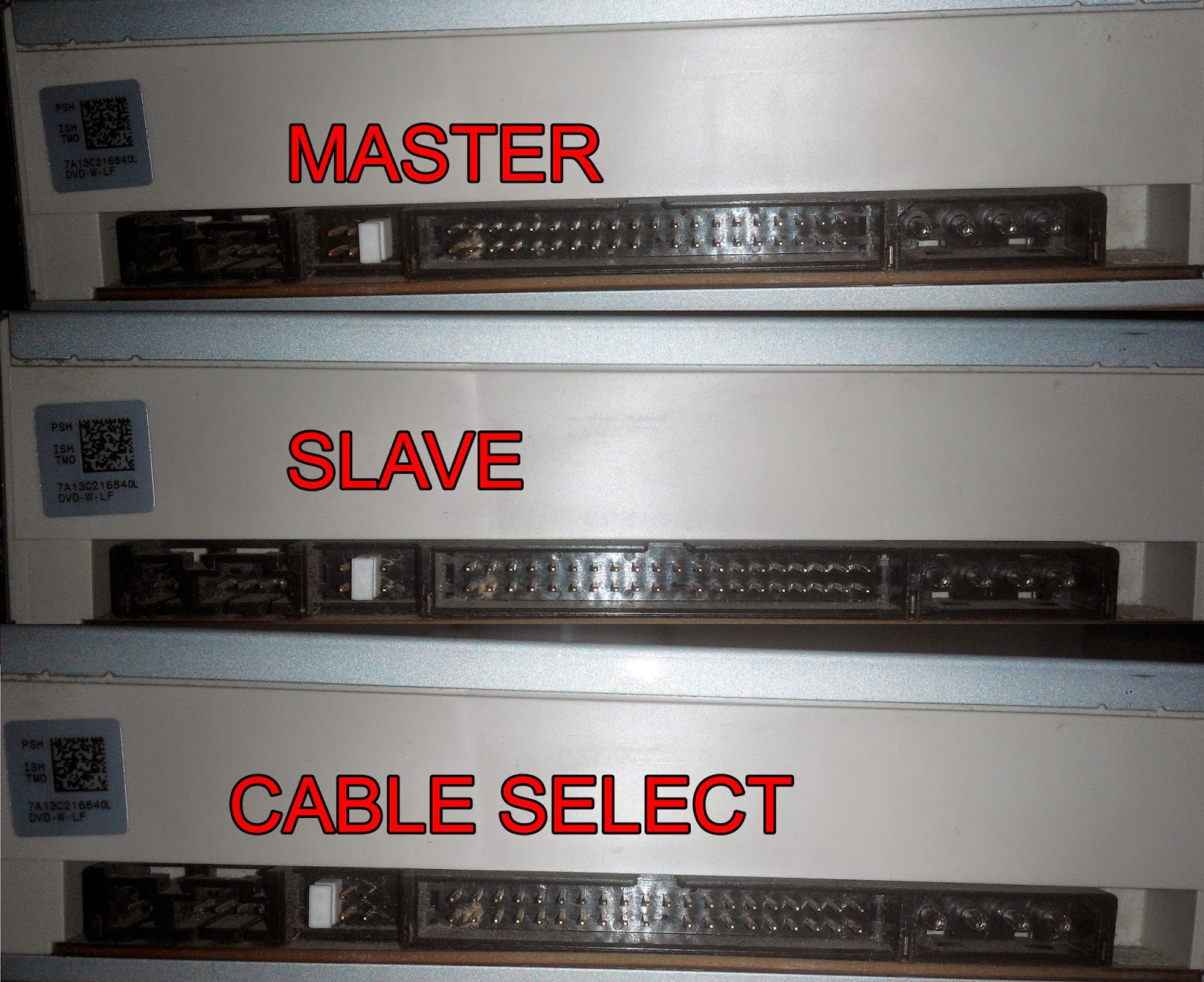
| Interface | Standard | PIO modes | DMA modes | Differences from IDE/ATA |
|---|---|---|---|---|
| IDE/ATA | ANSI | 0, 1, 2 | Single word 0, 1, 2; multiword 0 | |
| ATA-2 | ANSI | 0, 1, 2, 3, 4 | Single word 0, 1, 2; multiword 0, 1, 2 | Block transfer mode, LBA support, Improved identify drive command |
| Fast ATA | Marketing term | 0, 1, 2, 3 | Single word 0, 1, 2; multiword 0, 1 | Similar to ATA-2 |
| Fast ATA-2 | Marketing term | 0, 1, 2, 3, 4 | Single word 0, 1, 2; multiword 0, 1, 2 | Similar to ATA-2 |
| ATA-3 | Unofficial | 0, 1, 2, 3, 4 | Single word 0, 1, 2; multiword 0, 1, 2 | Similar to ATA-2, added support for transmission reliability at high speeds and SMART |
| Ultra ATA | Unofficial | 0, 1, 2, 3, 4 | Single word 0, 1, 2; multiword 0, 1, 2, 3 (DMA-33/66) | Similar to ATA-3 |
| ATAPI | ANSI | 0, 1, 2, 3, 4 | Single word 0, 1, 2; multiword 0, 1, 2 | Similar to ATA-2, added support for devices other than hard drives |
| EIDE | Marketing term | 0, 1, 2, 3, 4 | Single word 0, 1, 2; multiword 0, 1, 2 | ATA-2 + ATAPI and support for two host adapters |
Now let’s move on to a topic that is no less interesting.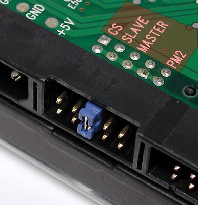 There are two parameters that characterize the data transfer rate when using an IDE / ATA hard disk. The internal transfer rate characterizes the transfer rate directly between the magnetic media and the internal buffer of the hard disk and is determined by the recording density, rotation speed, etc. These options depend on the design of the disk, not on the type of interface. On the other hand, the external baud rate, i.e. the baud rate of the IDE link, depends entirely on the baud mode used. In the early days of IDE/ATA disks, the speed of the disk subsystem was determined by the internal data transfer rate, which was obviously less than the external one. Currently, due to the increase in recording density (which allows you to shoot more information per disk revolution) and rotation speed, it is the external transfer rate that comes to the fore. What do the mode numbers mean anyway, and how does PIO differ from DMA?
The original common way to transfer data over the IDE/ATA interface was a protocol called Programmed I/O or PIO. There are five PIO modes that differ in maximum burst transfer rates. The common English name is PIO modes.
| Pio Mode | The maximum transmission speed (MV/s) | is maintained by standards |
|---|---|---|
| 0 | 3.3 | All |
| 1 | 5.2 | All |
| 2 | 8.3 | All |
| 3 | 11.1 | ATA-2, Fast ATA, Fast ATA-2, ATA-3, ATAPI, Ultra ATA, EIDE |
| 4 | 16.6 | ATA-2, Fast ATA-2, ATA-3, ATAPI?, Ultra ATA, EIDE |
determines the speed interface, not disk. It should also be taken into account (although this is hardly relevant now) that PIO modes 3 and 4 require the use of the VLB or PCI bus, since the ISA bus cannot provide a data transfer rate of more than 10 MB / s. Prior to the advent of DMA-33, the maximum data transfer rate for PIO and DMA modes was the same. The main disadvantage of PIO modes is that the processor controls the data transfer, which significantly increases its load.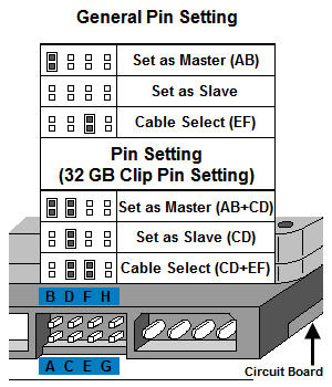 But these modes do not require special drivers and are ideal for single-tasking operating systems. It seems, however, that this is an endangered species …
Direct Memory Access (DMA) — a collective name for protocols that allow a peripheral device to transfer information directly to system memory without the participation of the central processor. Modern hard drives use this capability in combination with the ability to take control of the bus and manage the transfer of information themselves (bus mastering has been discussed in detail in the bus series). There are several DMA modes (DMA modes), which are listed in the table. It is worth noting that the so-called single word modes are currently not used and are given for comparison only.
| DMA mode | Maximum transfer rate (MB/s) | Supported by standards |
|---|---|---|
| Single word 1 | 4.2 | All |
| Single word 2 | 8.3 | All |
| Multiword 0 | 4. 2 2 |
All |
| Multiword 1 9 0177 | 13.3 | ATA-2, Fast ATA, Fast ATA-2, ATA-3, Ultra ATA , EIDE |
| Multiword 2 | 16.6 | ATA-2, Fast ATA-2, ATA-3, Ultra ATA, EIDE |
| Multiword 3 (DMA-33) | Ultra ATA( ATA/66) |
Another fun thing about the IDE/ATA interface is 32-bit disk access. As noted above, the IDE / ATA interface was and remains 16-bit. Reasonable question: Why, then, when you disable the drivers for 32-bit disk access in Windows, the speed of this disk drops? No less reasonable answer: First, how Windows works is a separate conversation. And secondly, the PCI bus, on which IDE host controllers are currently located, is 32-bit. Therefore, 16-bit transmission on this bus is a waste of bandwidth. Under normal conditions, the host controller forms one 32-bit packet from two 16-bit packets and forwards it further along the PCI bus (I repeat, I do not undertake to explain how Windows works with a disk).
We have seen the term block transfer mode above. In fact, this is just a mode that allows you to send multiple read / write commands in one interrupt. Modern IDE/ATA drives allow 16->32 sectors to be transferred in a «single interrupt». Since interrupts are generated less often, the processor load is reduced and the share of commands in the total amount of data transferred is reduced.
One or two devices can be connected to each IDE channel. In modern computers, as a rule, two IDE channels are installed (which corresponds to the EIDE specification), although it is theoretically possible to install up to 4 (!), Which allows you to connect 8 IDE devices. All IDE channels are peers. The usage of system resources by channels is shown in the table.
| Channel | IRQ | I/O Addresses | Support and Usage Issues |
|---|---|---|---|
| Primary | 14 | 1F0-1F7h and 3F6-3F7h | Used in all IDE/ATA computers |
| Secondary | 15 (10) | 170-177h and 376-377h | Widespread, present in almost all modern computers. |
| Tertiary | 11(12) | 1E8-1Efh and 3EE-3Efh | Rarely used. Possible problems with software |
| Quaternary | 10(11) | 168-16Fh and 36E-36Fh | Extremely rarely used. Problems with the software are very likely |
The resources used by the 3rd and 4th channels may conflict with other devices (for example, IRQ 12 is used by a PS / 2 mouse, IRQ 10 is usually occupied by a network card).
As mentioned above, each IDE / ATA interface channel supports the connection of two devices — master and slave. The configuration is usually set by a jumper on the back of the device. In addition to these two positions, there is usually a third one — cable select. What happens if you set the jumper to this position? It turns out that for devices to work in the cable select jumper position, a special Y-shaped cable is required, the central connector of which is connected to the system board. The extreme connectors of such a cable are unequal — a device connected to one connector automatically becomes a master, to another — a slave (similar to flops A and B). In this case, the jumpers on both devices must be in the cable select position. The main problem with this configuration is that it is exotic, although it is standard, and is not supported by everyone, so it’s quite difficult to find a Y-shaped cable (for example, I haven’t seen it, and it’s not entirely clear why this is needed) .
Apart from this exoticism, when configuring IDE/ATA devices, remember the following:
- Each channel can process only one request to one device at a time. The next request, even to another device, will wait for the current one to complete. Different channels can work independently. Therefore, you should not connect two actively used devices (for example, two hard drives) to the same channel. Ideally, each IDE device should be connected to a separate channel (this is perhaps the main advantage of SCSI).