JBAT1 | Hardware | Foros ADSLZone
Anonymous
Guest
-
-
#1
para que sirve el jbat1, es que viene unido con un plastikillo verde en mi placa base, y al kitarlo no se encendia, y al volverlo a poner se encendia de nuevo, que efecto tiene eso? por cierto, mi placa base es de unas de esas que tienen la bios trucada para no poder clockear ni suber el voltaje nada, sino las funciones basicas y gracias.. alguien sabe como kitar esas opciones con algun junper o algo? se puede?
gracias por todo
Dreadnought
Guru del Hardware
-
-
#2
el JBAT_1, por lo que comentas debe de tener algo que ver con la batería. .. Quizás sea similar al Clear_CMOS pero no lo tengo muy claro.
Respecto a la Bios capada, me temo que no puedes hacer nada ya que esas Bios vienen así porque el fabricante del ordenador lo pide.
Saludos
Anonymous
Guest
-
-
#3
hola de nuevo, soy el mismo de antes, he encontrado esto…
Clear CMOS jumper (normally JBAT1) must be set to “Keep settings” to allow the system to POST
If JBAT1 is set to “clear CMOS” position the motherboard will not power on or post
• On most MSI motherboards you will set JBAT1 as listed below
• JBAT1 pins 1-2 Keep settings
• JBAT1 pins 2-3 Clear CMOS settings
• Verify the correct setting for your motherboard in manual as the correct setting may vary from model to model
mi placa es una msi.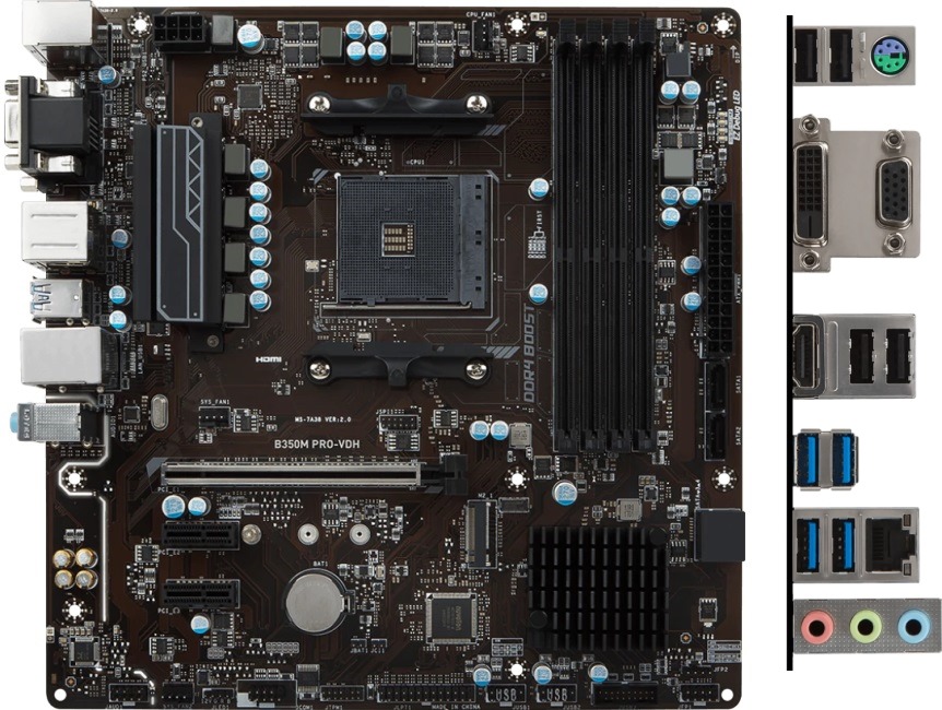 .. alguien sabe si al tocar eso desbloqueo mi bios… es que me interesaria gracias… o de algun otro modo ejejje
Xpolt
Usuari@ ADSLzone
-
-
#4
Pero el JBAT1 tiene tres pines, con un plastico que solo coje dos pines de los tres?
Saludos
Dreadnought
Guru del Hardware
-
-
#5
Lo que yo pensaba, es el Clear_CMOS jeje. Al cambiar de posción el Jumper lo que haces es resetear la Bios a sus parámetros originales, no la desbloqueas.
Saludos
Anonymous
Guest
-
-
#6
entonces, para el principiante que soy yo… si cojo los piner 1 y 2… le pasaria algo a mi ordenador?
se estropearia?, si los vuelvo a poner en 2_3 despues de arrancar con 1_2… se volvera a encender… es que como me as dicho que no lo toque?
por cierto.. si limpio la bios, saldra lo de los voltajes?ejejej
graicas de nuevo
Dreadnought
Guru del Hardware
-
-
#7
Con los pines 1 y 2 mantienes la configuración actual de la Bios, con los 2 y 3 reseteas la Bios a los valores de fábrica pero ello no te va a dejar ver los menús que tu quieres, que es probable que estén metidos, pero estarán protegidos de alguna manera. Las Bios de Gigabyte tienen algo similar en que ciertos menús sólo se desbloquean pulsando a la vez Ctrl+F1.
Saludos
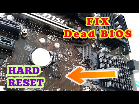
Fix BIOS Black Screen Problem in 2 minutes
2 minute read
Due to some misconfiguration in BIOS settings or after BIOS update, we may face BIOS Black Screen Problem in our computer. When this problem occurs no displays are shown on monitors. Here we talk How to Fix BIOS Black Screen Problem.
Why BIOS Black Screen Problem
When we change the Motherboard BIOS settings we may face this problem. Basically, if we change overclock settings of the RAM & processor which are not compatible with the hardware then BIOS Black Screen Problem will occur. If we enable BIOS default auto fallback on boot problem then if BIOS Black Screen Problem occurs, Motherboard will automatically change its settings to factory default setting. But most motherboard manufacturers make this auto fallback setting disabled by default.
Another time when we flash the BIOS or update the BIOS then we may encounter BIOS Black Screen Problem.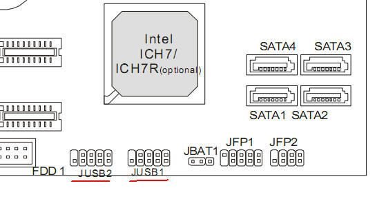 Basically, after flashing the latest BIOS, it tries to restore old settings which sometimes become incompatible. Then we face no display on our computer screen.
How to Fix BIOS Black Screen Problem
There are two ways to solve the issue. Either go to service center or try to Hard Reset BIOS CMOS by yourself. Hard reset using Motherboard Jumper is little bit tricky. But I promise if you follow me, any non technical person also can do this.
Hard Reset BIOS using Jumper
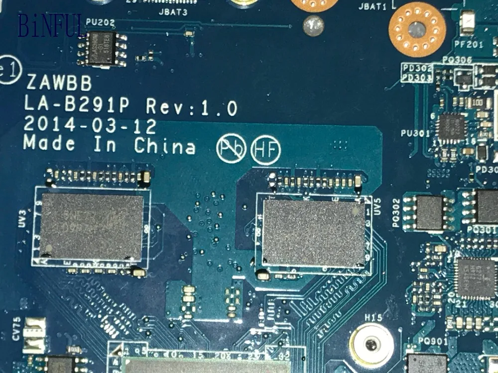
Almost every latest series of desktop motherboards does have a pair of jumper pins named “JBAT1”. Here in the above photo, we can see the JBAT1 Jumper pins near the Battery & NVME SSD slots. Here the motherboard used model name is MSI B450M Pro VDH-MAX.
Using any pin or screw driver top just short those two jumper pins for 10 seconds. Then switch on computer & you will see BIOS will loads up with factory default settings. Remember do not try to do this when the computer is on or power in given to the motherboard. Do this after unplugging power sockets from the electric board.
Video Tutorial BIOS Black Screen Problem
Still no Display?
If you can’t find the JBAT1 pins on your board after doing the above method still BIOS Black Screen Problem persists, I must recommend you to visit the nearest service center without any further experiments. It may void the warranty for any physical damage or short circuits.
Share
Tweet
Share
Pin it
Share
Share
Share
Share
Get Instant Updates of New Posts
Join our Telegram Channel
JOIN NOW
Related Posts
2 minute read
Contents Hide Problems of Background Noise Linux OSHow to enable Background Noise Cancelling Linux OSCommands for Noise Cancelling…
5 minute read
Contents Hide Desktop PC doesn’t have inbuilt BluetoothTwo Methods to connect Bluetooth Speaker with Desktop PCConnect Bluetooth Speaker…
3 minute read
Contents Hide How to Uninstall Oracle 12C Database from Windows CompletelyHow to Download Oracle 18cHow to installFix Common…
MSI Russia
October 6,2022
If after pressing the power button to turn on the computer, if the computer’s fans and LEDs start to work normally, but there is no display on the monitor, use the following troubleshooting steps to troubleshoot.
- Check compatibility with
- Check processor power cable connection
- Perform a POST test
- Reset BIOS
- Check indicator EZ Debug
processor
Check processor compatibility
To check the compatibility of the processor with the motherboard, go to the MSI official website, open the search field by clicking the corresponding icon in the upper right corner.
Enter the motherboard model name and press the Enter key.
Click the Compatibility link below the model name.
A list of compatible processor models can be found on the CPU tab.
If your processor is not listed, it does not meet MSI’s recommendations. For the best performance from your computer, you should use compatible processor models.
Check processor power cable connection
If you are using a compatible processor, make sure that the processor power cable is properly connected to the motherboard.
POST
Leave only the motherboard with the processor and processor cooling system, and one memory module in the computer.
Disable all peripherals such as USB sticks, hard drives, PCIe adapters.
Try to boot your computer. If it works fine, the problem is obviously with one of the peripherals. Add them to the system one at a time until you determine which one is causing the problem.
If the problem still persists, proceed with the diagnosis as described below.
Reset BIOS settings
Power off the computer. To do this, turn off its power supply using the appropriate button, or simply unplug the power cord from the electrical outlet.
Clear the BIOS settings by moving the JBAT1 jumper from its original position 1-2 to position 2-3.
Alternatively, remove the CMOS battery from the motherboard, wait 5 minutes, and then install it again.
Check the EZ Debug LED
The EZ Debug LED is located next to the 24-pin ATX power connector. It reflects the status of key components as the computer boots up. When a problem occurs, the corresponding LED lights up.
Processor light on: Reinstall the processor, check that the processor itself and its socket are not damaged.
Memory light on: Memory or processor not detected, not working properly, or incompatible with motherboard.
Video card LED on: The video card (or processor with integrated graphics core) is not detected or is not working properly.
Boot light on: No boot device detected or not working properly.
If the problem persists, try testing the monitor, video card, and video cable with another computer.
MSI
Motherboard User Manual
MSI Motherboard
Safety Information
- The components included in this kit are susceptible to electrostatic discharge (ESD) damage. Please adhere to the following instructions to ensure successful assembly of your computer.
- Check that all components are securely connected. A bad connection may cause the computer to not recognize the component or not start.

- Hold the motherboard by the edges to avoid touching sensitive components.
- We recommend that you wear an ESD wrist strap when handling the motherboard to prevent electrostatic damage. If an ESD wrist strap is not available, discharge static electricity from yourself by touching another metal object before handling the motherboard.
- Store the motherboard in an ESD container or on an antistatic pad if the motherboard is not installed.
- Before turning on the computer, check that there are no loose screws or metal parts on the motherboard or anywhere in the computer case.
- Do not boot your computer until installation is complete. This can result in permanent damage to components as well as injury to the user.
- If you need help with any part of the installation, contact a certified computer technician.
- Always turn off the power source and unplug the power cord from the electrical outlet before installing or removing any computer components.

- Save this manual for future reference.
- Protect the motherboard from moisture.
- Make sure your electrical outlet provides the same .tage as indicated on the power supply before connecting the power supply to the electrical outlet.
- Position the power cord so that it cannot be stepped on. Do not place anything on the power cord.
- Note all cautions and warnings on the motherboard.
- If any of the following occur, have service personnel check the motherboard:
- Liquid has entered the computer.
- The motherboard has been exposed to moisture.
- The motherboard is not working properly or you cannot get it to work according to the user manual.
- The motherboard has been dropped and damaged.
- The motherboard has obvious signs of failure.
- Do not leave the motherboard in temperatures above 60°C (140°F), as this may damage the motherboard.
Characteristics
| CP |
* Please refer to www. |
||||||||||||||||
| Expansion slots |
|
* Only available for processors with integrated graphics. * SATA4 will not be available when M. USB |
|
Internal connectors |
|
module Rear panel connectors |
|
9000 4x USB Portes 2. 9000 3X 3X LED feature |
|
BIOS |
|
.mbi-Bios Software for georadars |
|
128 Special capabilities
|
LAN Port LED Status Table Audio 7.
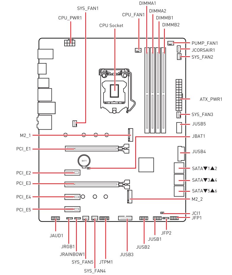
component overview* Distance from the center of the CPU to the nearest DIMM slot. CPU socketPlease install the CPU into the CPU socket as shown below. Important
DIMM slotsInstall the memory module in the DIMM slot as shown below. Important
M2_1: M.2 slot (M key)Install an M.2 device in the M.2_1 slot as shown below. M2_2: M.2 slot (E key)Install the Wi-Fi module in the M.2_2 slot as shown below. PCI_E1 ~ 2: PCIe expansion slots Read the add-in card documentation to see if there are additional hardware or software changes required. SATA1~4: SATA 6Gb/s connectorsThese connectors are SATA 6Gb/s interface ports. Each connector can connect to one SATA device. Important
JAUD1: Front audio connectorThis connector allows you to connect the front panel audio connectors. JFP1, JFP2: front panel connectors These connectors connect to switches and LEDs on the front panel. ATX_PWR1, CPU_PWR1: power connectorsThese connectors allow you to connect an ATX power supply. Important JUSB1: USB 2.0 connectorThis connector allows you to connect USB 2.0 ports on the front panel. Important
JUSB2: USB 3.2 Gen 1 5 Gb/s connectorThis connector allows you to connect USB 3.2 Gen 1 5 Gb/s ports on the front panel. Important CPU_FAN1, SYS_FAN1: fan connectors The fan connectors in PWM mode provide a constant 12V output and control the fan speed with a speed control signal.
|
 msi.com for more information on compatible memory.
  2 SATA SSD slot is installed.
  0
0
 1 channel configuration

 When you connect a 3-pin fan (no PWM) to the fan header in PWM mode, the fan speed will always be kept at 100%, which can create a lot of noise.


 When warning message is displayed GOP (Graphics Output Protocol) support is not detected on this video card. .
 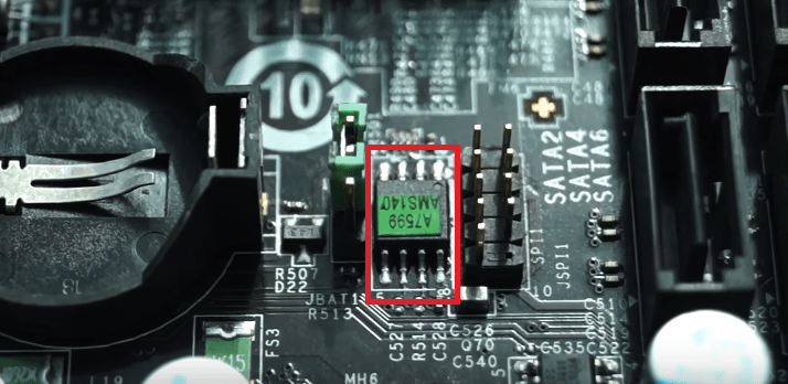 Therefore, the description may differ slightly from the latest BIOS version and is for reference only. You can also refer to the HELP information panel for a description of the BIOS item.
 And then save the BIOS file to a USB flash drive.