Manage 3D Settings (reference)
Manage 3D Settings (reference)
The Manage 3D Settings page enables you to
Global Settings
From the Global Settings tab, you can select from a list of pre-installed
global settings (for workstation products) or create your own custom settings
to use when running 3D applications.
See Setting the Preferred Graphics Processor for information about a change in functionality in newer Windows 10 operating systems regarding setting the preferred graphics processor.
-
Preferred
graphics processor (Only on systems using NVIDIA’s power-saving
GPU technology.) From the options in the list box, you can specify to -
Use high-performance NVIDIA processor for maximum performance or for decoding all video played on displays connected to the integrated graphics, or
-
Use integrated graphics for longer battery life or for decoding all video content played on displays connected to the integrated graphics, or
-
Let the driver auto-select the most compatible graphics processor, depending on the program or video codec.
Notes:
-
Programs and videos that launch
on external displays that are driven by the NVIDIA GPU will always use
the NVIDIA GPU rather than the integrated graphics processor. -
When you modify the «Preferred
Graphics Processor» setting, programs that are already running will
continue to use the same graphics processor uninterrupted. To allow the
«Preferred Graphics Processor» settings to take effect, you
must restart the program. -
Restore
button (bottom corner) restores the default global settings. -
Restore
button (Global presets) restores the settings for the selected global
preset to the default settings.
Program Settings
From the Program Settings tab, you can create a set of 3D settings to
use when running a particular game or application.
See Setting the Preferred Graphics Processor for information about a change in functionality in newer Windows 10 operating systems regarding setting the preferred graphics processor.
-
Add
launches the Add dialogue box which lists recently used programs, games,
and Windows Store apps (under
Windows 8). You can either select from the list or click Browse so
you can navigate and locate the program or folder for which you want
to establish unique settings. -
Remove
button deletes the game-settings association. Use this button to remove
the game/settings association that you created when you no longer want
the game to use the assigned settings. Pre-installed settings cannot be
removed. -
Restore
button restores the settings for the selected program to the default settings. -
Show
only programs found on my computer. Check this box if you want
the list to show only those games that are installed on your system. The
driver can still detect any games that are played and apply the appropriate
3D settings, even if the installed-game list filter does not detect the
game on the system.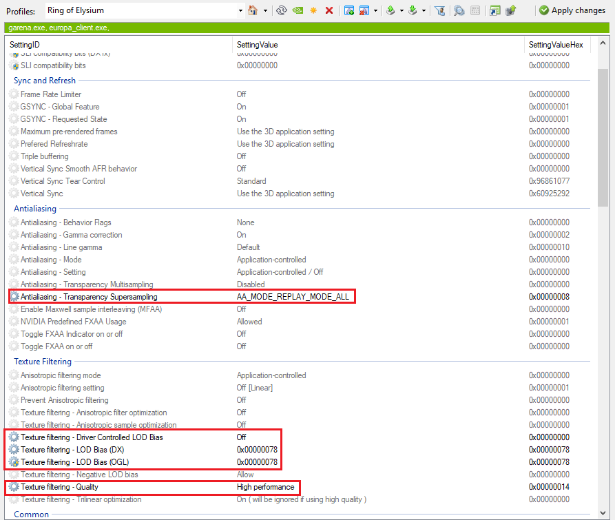
-
Preferred
graphics processor (Only on systems using NVIDIA’s power-saving
GPU technology.) From the options in the list box, you can specify to -
Use high-performance NVIDIA processor for maximum performance or for decoding all video played on displays connected to the integrated graphics, or
-
Use integrated graphics for longer battery life or for decoding all video content played on displays connected to the integrated graphics, or
-
Let the driver auto-select the most compatible graphics processor, depending on the program or video codec.
Notes:
-
Programs and videos that launch
on external displays that are driven by the NVIDIA GPU will always use
the NVIDIA GPU rather than the integrated graphics processor. -
When you modify the «Preferred
Graphics Processor» setting, programs that are already running will
continue to use the same graphics processor uninterrupted. To allow the
«Preferred Graphics Processor» settings to take effect, you
must restart the program.
The Global Settings and Program Settings tabs include a list of features
that you can set. The actual features that appear depend on the graphics
card and application.
Ambient Occlusion enhances depth
perception and adds realism to 3D scenes by providing a soft shadow effect
to objects based on their placement in the scene. Select the level that
provides the best balance between realistic effects and graphics performance.
This feature is not supported on all applications. Refer to this feature
from the Program Settings tab to see if it is supported with your application.
NOTE: This feature requires the following
minimum OS, API, and hardware:
Anisotropic filtering is a technique
used to improve the quality of textures applied to the surfaces of 3D
objects when drawn at a sharp angle. Enabling this option improves image
quality at the expense of some performance. You can choose either to let
the application determine the anisotropic filtering settings, turn anisotropic
filtering completely off, or select from a number available settings.
Higher values yield better image quality while reducing performance.
Antialiasing — Mode allows
you to control how NVIDIA antialiasing
is applied in your 3D applications. See also Tips for Setting
Antialiasing.
NOTE: This feature is
available only
with GeForce 8 Series and later GPUs.
-
Off
turns off antialiasing. -
Application-controlled
lets the application control the antialiasing level. This is the preferred
setting to use for applications that have built-in antialiasing controls. -
Enhance
the application setting (with the settings specified under Antialiasing-Setting) provides the
most reliable and highest quality antialiasing support if you want to
use NVIDIA’s antialiasing with applications that have built-in antialiasing
controls.
-
Override
any application setting (with the settings specified under Antialiasing-Setting) can be used if
your application does not have built-in antialiasing control, or if your
application uses high dynamic range (HDR) rendering but the built-in antialiasing
does not work when HDR is enabled.
To use this option, you
must set the application’s antialiasing to any level, such as 2x, then
set NVIDIA’s antialiasing using the Antialiasing
— Setting feature. The NVIDIA antialiasing setting is applied regardless
of the application’s setting.
To use NVIDIA’s antialiasing with applications that
have built-in antialiasing controls, use Enhance
the application setting.
Antialiasing — Setting allows
you to set the antialiasing level to use
in your 3D applications. You can choose either to let the application
determine the antialiasing settings, turn antialiasing completely off,
or select from a number of available settings.
NOTE: This feature is
available on all GPUs. However, for GeForce 8 Series and later GPUs, this
item is read-only if Application-controlled
or Off was selected under Antialiasing — Mode.
-
Application-controlled
lets the application control the antialiasing level. This is the
preferred setting to use for applications that have built-in antialiasing
controls. -
None
turns off antialiasing. -
Specific
antialiasing settings: The higher value corresponds to a higher
level of antialiasing. For example, 16x is a higher quality setting than
2x.
See Tips
for Setting Antialiasing.
Antialiasing — FXAA improves
the image quality of programs with less of a performance impact than other
antialiasing settings. While this setting can be
used in conjunction with other antialiasing settings, it is especially
useful for programs that do not support hardware-based antialiasing.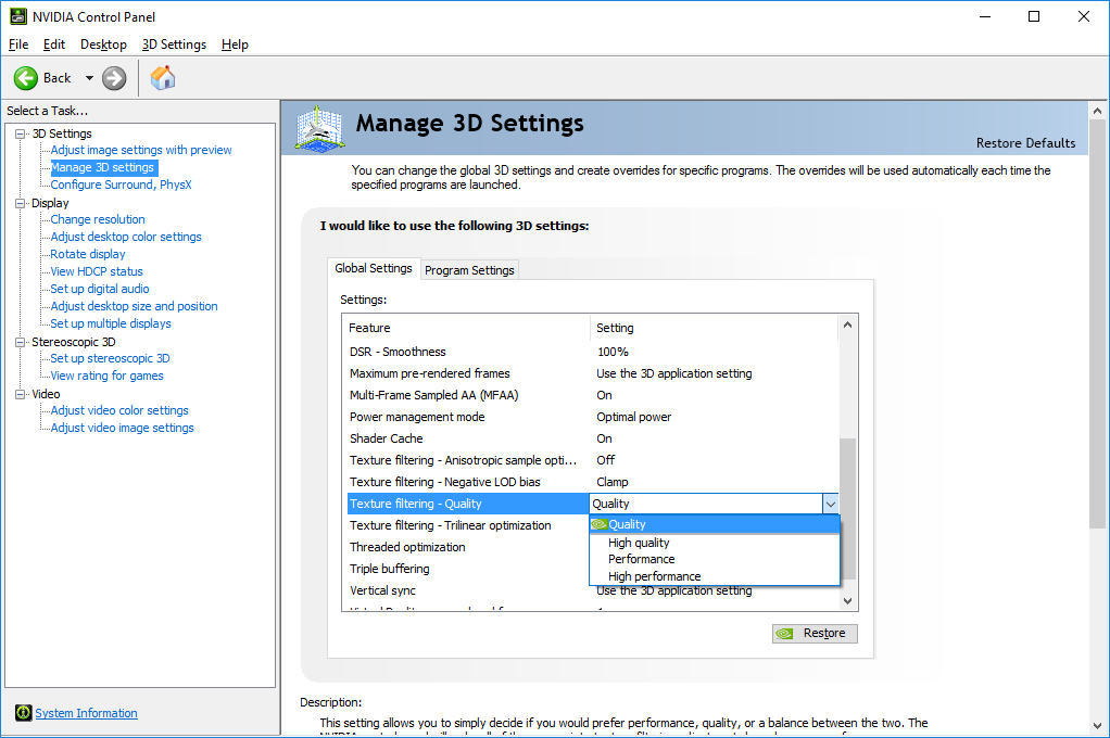
Antialiasing line gamma improves
the colour and quality of 3D lines in OpenGL programs.
Antialiasing — Gamma correction
allows you to enable or disable gamma correction antialiasing to improve
the colour and quality of 3D images in OpenGL programs.
Antialiasing — Transparency allows
you to minimise the visible aliasing on the edges of images with transparent
textures.
-
Multisampling
provides superior performance. -
Supersampling
provides superior quality. -
With newer GPUs, specific antialiasing
settings are available, limited by the value chosen under Antialiasing
— Settings. For example, if you selected 4x AA, then the available
transparency antialiasing values are 1x, 2x, and 4x, but not 8x.
Background Application Max Frame Rate sets the maximum frame rate that the GPU will render a game or 3D application running in the background. This helps reduce power consumption or fan noise when switching to an application while leaving another game or application running in the background. Range: 20-200
Buffer-flipping mode determines
how the video buffer is copied to the screen in OpenGL programs.
CUDA — GPUs lets you specify
one or more GPUs to use for CUDA applications. GPUs that are not selected
will not be used for CUDA applications.
NOTE: At least one GPU
must be selected in order to enable PhysX GPU acceleration.
CUDA — Double precision lets
you select the GeForce GPUs on which to enable increased double-precision
performance for applications that use double-precision calculations. Available
on GeForce GPUs with the capability for increased double-precision performance.
NOTE: Selecting a GPU reduces performance
for applications that do not use double-precision calculations, including
games. To increase game performance, do not select any GPUs.
Deep colour for 3D applications allows
OpenGL 3D applications to be displayed in a colour depth higher than what
is supported by the Windows desktop. The application and the monitor must
be capable of rendering deep colour content.
Dynamic Boost maximises system performance by dynamically shifting power between the GPU and the CPU. Available with R445 and later drivers.
Enable overlay allows use of
OpenGL overlay planes.
Exported pixel types determines
the overlay pixel format to export so that OpenGL applications can use
overlays. Format options include colour-indexed (8-bpp), RGB555, or both
colour-indexed (8-bpp) and RGB555 format.
Image Scaling (GeForce GPUs — introduced in R495 drivers) boosts application frame rates and lets you increase the level of sharpness, detail, or clarity of images in games and applications.
-
Off (default) disables image scaling and sharpening controls.
-
On (GPU Scaling & Sharpening) boosts frame rates for the application and enables the following controls.
-
Sharpen: Adjust the level of sharpness. Acceptable range: 0-100%
-
Overlay Indicator: When selected, an overlay will indicate whether the feature is enabled for a particular application or properly captured in screen shots or videos. Blue text indicates sharpening is active. Green text indicates that sharpening and upscaling are active.
With Image Scaling enabled, additional resolutions are added to the resolution list on the Change Resolution page and GPU scaling is set on the Adjust Desktop Size and Position page. You can also create custom display modes while this feature is enabled.
-
Image Sharpening (Quadro GPUs — introduced in R440 drivers) lets you increase the level of sharpness, detail, or clarity of images in games and applications. This and the GPU Upscaling feature are introduced in R440 drivers.
-
Sharpening Off (default) disables the image sharpening controls.
-
Sharpening On enables the following image sharpening slider controls.
-
GPU Upscaling: Select this tick box to enable GPU upscaling on resolutions at or below the native resolution for all DirectX, Vulkan, and OpenGL games. When enabled, predefined resolutions are added to the resolution list on the Change Resolution page, and GPU scaling is set on the Adjust Desktop Size and Position page. You can also create custom display modes while this feature is enabled.
Low Latency Mode reduces latency by limiting the number of frames the CPU can prepare before the frames are processed by the GPU. This feature was introduced in R435 drivers.
-
Off (default) prioritises render throughput by allowing games to queue frames.
-
On prioritises latency by limiting queued frames to one.
-
Ultra prioritises latency by fully minimising queued frames.
Max Frame Rate lets you set the maximum 3D game or application frame rate that the GPU will render. Limiting the frame rate can be useful for extending battery life or for reducing system latency in certain scenarios. Introduced in R440 drivers.
Monitor Technology selects the technique used to control the refresh policy of the connected monitor.
-
G-SYNC: Requires a G-SYNC capable display. Select this option to eliminate screen tearing, while minimising input lag and stutter.
-
ULMB: Select this option (Ultra Low Motion Blur) if you prefer to improve motion blur instead of using G-SYNC.
-
Fixed Refresh Rate: Select this option to use the set refresh rate of the display without any variability or adaptation.
Multi-display/mixed-GPU acceleration.
Determines advanced OpenGL rendering options
when using multiple displays and/or graphics cards, based on different
classes of NVIDIA GPUs.
-
Single
display performance mode: Specify this setting if you have problems
with the multi-display modes. -
Compatibility
performance mode is useful if you have two or more active displays
when running in nView Dualview display mode or if you are using different
classes of NVIDIA GPU-based graphics cards.
Note: When
this mode is in effect, OpenGL renders in «compatibility» mode
for all displays. In this mode, when different classes of GPUs are in
use, the lowest common feature set of all active GPUs is exposed to OpenGL
applications. The OpenGL rendering performance is slightly slower than
in single-display mode.
Note: When
this mode is in effect, OpenGL renders in «performance» mode
for all displays. As in «compatibility» mode, when different
classes of GPUs are in use, the lowest common feature set of all active
GPUs is exposed to OpenGL applications. However, the rendering performance
is «faster» than in compatibility mode, although switching or
spanning displays may result in minor transient rendering artifacts.
Multi-GPU performance mode determines
the rendering mode used in multi-GPU mode. You can select single-GPU mode
or one of several multi-GPU rendering modes.
Power management mode lets you
set how your graphics card’s performance level changes when running most
DirectX or OpenGL 3D applications.
Note: This control is
available only on GeForce 9 series and later GPUs.
-
NVIDIA driver controlled: Let the driver determine the best settings for performance and image quality. Typically, the GPU will operate at maximum performance when using SDI, G-Sync, or Mosaic features.
-
Adaptive:
Save power by letting the graphics driver reduce GPU performance depending
on the needs of the 3D application. -
Prefer
maximum performance: Use the GPU only at
maximum performance when running most 3D applications. -
Prefer consistent performance: Maintain the GPU at a consistent performance state when 3D applications are running. This setting is often used to provide reproducible results during software development and tuning.
OpenGL Rendering GPU lets you
select which GPU to use for OpenGL applications. If one GPU from an SLI
or Mosaic group is selected, then all GPUs in that group are used. Select
Auto select to let the driver
decide which GPU to use.
Note: This control is
available only on Windows Vista and later Windows operating systems.
Preferred refresh rate (<monitor
name>) lets you override the refresh rate limitations imposed
by the 3D application for the indicated monitor. This
is particularly useful when viewing games in 3D stereo.
-
Application-controlled:
Let the 3D application decide the optimum refresh rate. -
Highest
Available: Override the 3D application’s
setting with the highest available refresh rate to take advantage of high
refresh rate displays and to enhance image quality.
If NVIDIA Stereoscopic 3D is installed but not enabled,
then the «Application Controlled» option is forced and cannot
be changed.
If your application does not perform properly when
using the «Highest Available» option, then select «Application-controlled»
instead.
Notes:
-
This control is available only
on Windows Vista and later Windows operating systems. -
This control is not available
for applications identified as not supporting this feature. -
If NVIDIA Stereoscopic 3D is installed
and enabled, then the option is set to «Controlled by Stereo»
and cannot be changed.You can see the refresh rate set in the Stereoscopic
3D «Test Stereoscopic 3D» dialogue box. -
This control is disabled if
variable refresh rate is enabled.
Shader Cache Size (introduced in Release 495) controls the maximum amount of disk space the driver may use for storing shader compiles. Shader compiles are normally performed each time a game runs and are a common cause of game-play stuttering. The shader cache stores these compiled shaders so that subsequent runs of the same game do not need to perform the shader compilation.
Note: Installing a new driver will delete the cache; you may experience game play stutters the first time you run a game after installing a driver.
-
Current options include Disabled, Unlimited, or one of the following values: 128 MB, 256 MB, 512 MB, 1 GB, 5 GB, 10 GB, 100 GB
-
Guidelines: Set a size limit which is large enough to cover the set of games you normally use, but not too large that it exceeds your available hard drive disk space.
-
Games vary greatly in the amount of cache space they require; higher end games may require several hundred megabytes.
-
On approaching the size limit, the driver will remove older shaders from the cache to make space for newer shaders; setting a size limit too small may cause the driver to remove shaders you still make use of and cause game play stutters.
-
SILK Smoothness reduces stutter in games caused by variations in CPU or GPU workloads. It does this by smoothing out animation and presentation cadence using animation prediction and a post-render smoothing buffer.
Note: Selecting High or Ultra can increase lag during gameplay, and may not be appropriate for first person shooter or competitive gaming.
SLI performance mode determines
the rendering mode used in SLI mode. You can select single-GPU mode, one
of several SLI rendering modes, or SLI antialiasing mode which combines
the power of multiple GPUs to offer higher quality antialiasing. Each
of these modes are mutually exclusive.
Stereo — Display mode allows
you to select the display mode for stereo glasses or other hardware. Refer
to the hardware documentation to learn which mode to use. Applies to Quadro
cards running OpenGL stereo programs, as well as DirectX consumer stereo
when stereoscopic 3D is enabled.
Stereo — Enabled. Turn
on this option only if it is necessary. Some applications automatically
choose a stereo format while other applications may not function properly
in a stereo pixel format. Applies to Quadro cards running OpenGL
stereo programs, as well as DirectX consumer stereo when stereoscopic
3D is enabled. This option is turned off if variable refresh rate is enabled.
Stereo — Force shuttering. This
setting forces the toggling of the stereo signal when shutter glasses
or other 3D stereo hardware are not detected. Applies
to OpenGL stereo programs.
Stereo — Swap eyes. Turn on
this option to switch the left and right stereo images if the stereo effect
does not appear correctly with the current setting. Applies to Quadro
cards running OpenGL stereo programs, as well as DirectX consumer stereo
when stereoscopic 3D is enabled.
Stereo — Swap mode. For active, frame sequential stereo, select when each stereo eye is updated with the next frame.
The maximum application frame rate is equal to the current display refresh rate. This setting is useful for applications that should run at the highest possible frame rate.
The maximum application frame rate is equal to half the display refresh rate. This setting is useful for stereo projectors that use a frequency doubling mechanism.
Texture filtering — Anisotropic filter
optimisation improves performance by limiting trilinear filtering
to the primary texture stage where the general appearance and colour of
objects is determined. This improves performance with minimal loss in
image quality. This setting only affects DirectX programs.
Texture filtering — Anisotropic sample
optimisation limits the number of anisotropic samples used based
on texel size. This setting only affects DirectX programs.
Texture filtering — Negative LOD bias determines if a negative level of detail bias is used to sharpen
texture filtering.
Texture filtering — Quality allows
you to decide if you would prefer performance, quality, or a balance between
the two. The NVIDIA Control Panel will make all of the appropriate 3D
image adjustments based on your preference.
-
High performance offers the highest frame rate possible resulting in the best performance for your applications.
-
Performance offers an optimal blend of image quality and performance. The result is optimal performance and good image quality for your applications.
-
Quality (default setting for GeForce products) results in optimal image quality for your applications.
-
High Quality (default setting for Quadro products) results in the best image quality for your applications. This setting is not necessary for average users who run game applications. It is designed for more advanced users to generate images that do not take advantage of the programming capability of the texture filtering hardware.
Texture filtering — Trilinear optimisation
improves texture filtering performance by allowing bilinear filtering
on textures in parts of the scene where trilinear filtering is not necessary.
This setting only affects DirectX programs.
Threaded optimisation allows
applications to take advantage of multiple CPUs.
Triple buffering allows you to enable or disable triple buffering in OpenGL applications. Turning on this setting improves performance when Vertical sync is also turned on.
Unified back/depth buffer. Enabling
this option allocates one back buffer and one depth buffer for applications
that create multiple windows. Turn on this option to use video memory
more efficiently and improve performance.
Vertical sync allows you to
control Vertical Synchronisation mode, where the application’s frame rate
is synchronised with the display refresh rate in order to eliminate tearing.
NOTE: The following Vertical Sync setting values are applicable only when a display is connected to the NVIDIA GPU.
-
Use
the application setting to use the settings within the application
to control V-Sync. -
Off
is useful if performance is more important than image quality. -
On
is useful for eliminating tearing. -
Adaptive turns V-Sync On only when the frame rate is faster than the refresh rate. This eliminates tearing at high frame rates, and stuttering at lower frame rates.
This setting is available only if Monitor Technology is set to ULMB or Fixed Refresh Rate.
-
Adaptive 1/2 refresh rate turns V-Sync On only if the frame rate is faster than half the refresh rate. This eliminates tearing at high frame rates, and stuttering at extremely low frame rates. This setting is available only if Monitor Technology is set to ULMB or Fixed Refresh Rate.
-
Fast improves latency without introducing tearing. Available on Pascal and later GPUs, on single-GPU configurations.
Virtual Reality — Variable Rate Super Sampling improves image quality by applying super sampling selectively to the central region of a frame — the critical area for Virtual Reality headsets. Applies to NVIDIA-profiled applications on NVIDIA Turing GPUs when MSAA is enabled. The maximum super sampling applied depends on the MSAA level used in the application. Introduced in R440 drivers.
-
Adaptive applies super sampling to the central region of a frame, provided there is enough GPU headroom.
The size of the central region varies according to the amount of GPU headroom available.
-
Always On applies super sampling to a fixed-size central region of a frame. This mode does not consider GPU headroom availability and may result in frame drops.
-
Off (default) disables the feature.
WhisperMode is an ultra-efficient mode that makes your plugged-in laptop run quieter while gaming. It works by intelligently pacing the game’s frame rate while simultaneously configuring the graphics settings for optimal power-efficiency. Available on GeForce GTX 10-series laptop GPUs or higher, on single-GPU configurations. To see the WhisperMode controls in the NVIDIA Control Panel on supported systems, you must first enable WhisperMode using GeForce Experience.
-
Off: Disabled by GeForce Experience
-
On: Enabled by GeForce Experience and applied as a Global Setting. Frame rates are capped at 40 or 60 fps, depending on the application.
-
WhisperMode slider: Appears under Program Settings when enabled in GeForce Experience. Move the slider to the left (decrease the maximum frame rate) for quieter gaming, or to the right (increase the maximum frame rate) for higher performance.
Guide | Nvidia Control Panel 3D Settings Optimization
The Nvidia Control Panel is perhaps one of my most visited applications. I hang around its 3D Settings a lot, since I do check out new stuffs that Nvidia could possibly roll out. We also make sure to use the same settings on our graphics card as well – every time we review stuff.
Most of the settings within the control panel are prevalent at the graphic settings of most games, especially AAA titles, so knowing them should mean a huge plus on your side as a gamer.
But first, the easy way
Setting parameters around the 3D Settings easily is possible under the Adjust Image Settings with Preview. But, it is still best to familiarize yourself with the technologies and features behind your graphics card. Using the slider forces some features to be turned on and off and while it’s easy it is not optimally the best way to tweak stuffs.
Using the slider at the Adjust Image Settings is not ideal but you could start there.
On this guide, we will explain the different settings found within Nvidia’s Control Panel (Game Ready Driver 378.66.). Some settings here are also graphics and display dependent. the G-SYNC setting for example requires a G-SYNC capable monitor to be displayed. If the setting here doesn’t reflect yours, check out your setup and driver.
If you managed to screw up, you could always restore the default values with a push of a button.
Ambient Occlusion:
Ambient Occlusion is simply put, a lighting effect that drastically improves shadows on geometries. It does so by calculating the brightness of a pixel in relation to the nearby objects. It also determines which pixels are blocked from the environmental light by geometry – reducing the brightness values.
| Off | Turns AO off, application controlled |
| Performance | Turns AO on, driver override, good image quality |
| Quality | Turns AO on, driver override, maximum image quality |
Ambient Occlusion is tuned off by default, since games had their own settings which is usually HBAO and SSAO. SSAO is the best AO method in term of performance while HBAO will provide you the best image quality. If the game doesn’t support AO, then you could use the drop down menu to toggle activation.
Anisotropic Filtering:
To explain it simply, Anisotropic Filtering refers to a non-linear texture filtering method, superseding Trilinear filtering. It enhance the image quality of textures on surfaces by reducing fuzziness and blur – preserving detail at extreme viewing angles.
| Application Controlled | Turns AF on, application controlled |
| Off | Turns AF off, driver override |
| 2x | Turns AF on, driver override |
| 4x | Turns AF on, driver override |
| 8x | Turns AF on, driver override |
| 16x | Turns AF on, driver override |
Anisotropic Filtering has 6 options available at the Nvidia Control Panel. By default it is Application Controlled, which means you could set the parameters within the game yourself. I do not suggest turning this off but rather experiment in-game or at the Nvidia Control Panel which suites you best. If every inch of performance increase is a must, turn if off then.
Antialiasing FXAA:
Aliasing refers to jagged, or stair-like visual artifacts at the edges of a 3D object. Antialiasing combats that artifact. Now FXAA or Fast Approximate Anti-Aliasing is really fast and efficient by simply analyzing the pixels on the screen. There are tons of Antialiasing techniques out there with the Nvidia Control Panel offering FXAA injection and Off as options. It defaults at Off since games naturally had their own AA options. FXAA is a developer implemented shader technique so support still depends on the game.
Any Antialiasing method improves image quality especially at lower resolutions but it also impacts performance. It is best to play with the in-game AA options for your performance and image quality needs but if maximum performance is required then turn it off.
Antialiasing Gamma Correction:
Antialiasing Gamma Correction refers to the correction of brightness values within an AA enhanced image. Setting this on and off has no performance impact but has an effect on the brightness of some antialiased textures. I usually had this turned off, but if enabling it pleasing you then there’s no stopping you from turning it on.
Antialiasing Mode:
Antialiasing mode has four options. Application Controlled means that you could select AA options within the game, while Off disables it. Enhanced allows you to set the AA settings in-game with the graphics driver allowing refined tuning via the Antialiasing – Settings drop down menu.
| Application Controlled | Turns AA on, application controlled |
| Off | Turns AA off, driver override |
| Enhanced | Turns AA on, driver override, enhances in-game AA |
| Override | Turns AA on, driver override, overrides in-game AA |
Override is best used for titles that doesn’t support AA. It enables the same Antialiasing – Settings drop down menu. Some games do not work optimally by settings this option to Override and I’d rather inject FXAA than using any other options here. Application Controlled is best while turning this Off ensures maximum performance.
Antialiasing Transparency:
This is pretty much another AA implementation (Transparency Antialiasing) but it is taxing at its core. This setting is turned off by default.
| Off | Turns AT off, application controlled |
| MSAA | Turns AT-MSAA on, driver override |
| 2x SSAA | Turns AT-2x SSAA on, driver override |
| 4x SSAA | Turns AT-4x SSAA on, driver override |
| 8x SSAA | Turns AT-8x SSAA on, driver override |
MSAA is the best when it comes to performance and image quality, but turning it off ensures that the in-game Transparency Antialiasing could be set by the user. You can mix this with FXAA but for maximum performance, leave this turned off.
CUDA GPUs:
The CUDA GPU option within the Nvidia Control Panel allows you to select which graphics processing unit will use CUDA for general computing functions. Games with Nvidia PhysX technology benefits with CUDA enabled GPUs. Select all for the best possible performance.
DSR Factor:
DSR or Dynamic Super Resolution is basically an improved down sampling method. It allows the graphics card to render the game at a higher resolution than your display could provide and outputs it using your native resolution. DSR also allows you to experiment with non native resolutions.
| Display at 1920 x 1080 Resolution | |
| Off | Downsampling turned off |
| 1.20x | Downsampling turned on, 2130 x 1183 |
| 1.50x | Downsampling turned on, 2351 x 1323 |
| 1.78x | Downsampling turned on, 2560 x 1440 |
| 2.00x | Downsampling turned on, 2715 x 1527 |
| 2.25x | Downsampling turned on, 2880 x 1620 |
| 3. |
Downsampling turned on, 3325 x 1871 |
| 4.00x | Downsampling turned on, 3840 x 2160 |
This method is like anti-aliasing on steriods but unlike Antialising, DSR allows you to enhance any game’s image quality regardless of age. If your native resolution is 1920 x 1080 and you’ve set the factor to 4.00x, the effective resolution will be 3840 x 2160P. It’s like a poorman’s 4K experience on a 1080P display.
DSR Smoothness:
Since DSR is effectively down sampling, smoothing is required depending on your selected DSR Factor. The value defaults at 33%. Lower values means sharper, while higher values means softer textures. I usually turn off smoothness with a DSR Factor of 4.00x, while at lower resolutions the default 33% value will do. Do these changes if you are willing to use DSR.
There is no noticeable performance impact with this setting so play at your will if you enabled the DSR Factor.
Maximum Pre-rendered Frames:
Simply put, Maximum Pre-rendered Frames pertains to the Graphics Pipeline’s Context Queue. It is a buffer used to store data in preparation to be used by the GPU. How much frame should be prepared ahead is govern by this setting. Some games will perform better with the setting at low (1), while others requires higher values (4). It is best to keep this setting at default. Use the 3D Application Settings.
Monitor Technology:
This setting refers to the refresh rate and anti-blur technologies used by the display. This setting applies to G-SYNC, ULMB (Strobe), and Fixed Refresh (normal displays). We could talk all day long about this one but simply put if you have a ULMB or G-SYNC display, you could set the features enabled here. We’ll reserve this for another article.
| G-SYNC | Anti screen tearing, variable refresh rate |
| ULMB (Strobe) | Anti motion blur, PWM, lower brightness |
| Fixed Refresh | Uses the refresh rate of the display |
There is no best setting here, since no one prefers the same thing. G-SYNC is good for those who hates screen tearing, while ULMB is good for those who wants to eliminate motion blur on displays. Personally, I’d rather have ULMB enabled if my display could use it. You cannot use both technologies at the same time but V-SYNC and ULMB is possible.
Multi-Frame Sampled AA:
MFAA refers to another AA method, similar to MSAA but it doesn’t feature the same performance impact. This AA setting requires a GTX 900 series card and above while also requiring in-game support.
I prefer this over MSAA if the title supports it. It’s technically 2xMSAA, with anti-aliasing properties equivalent to 4xMSAA. But for the best performance, leave it turned off.
Multi-Display / Mixed GPU Acceleration:
This setting refers on how OpenGL applications manipulate rendering with multiple displays. There are 3 modes here with multiple display, single display and compatibility performance mode.
| Multi-Display | Optimized for multi-display setups |
| Single-Display | Optimized for single-display setups |
| Compatibility | Use this if the OpenGL application has issues with multi or single-display |
Power Management Mode:
Modern GPUs can set their power usage under various scenarios and this setting pertains to that feature. Adaptive is where the GPU down clocks to save energy when the GPU load is not that high. This is great, but older or not so demanding titles could pose an issue with this setting. Maximum performance ensures that the GPU clock stays at its maximum, regardless of GPU usage.
| Optimal Power | Similar to Adaptive, best power saving |
| Adaptive | Variable clock speed, power saving |
| Prefer Maximum Performance | Base clock speed, maximum performance |
Optimal is fairly new, but think of it as Adaptive on steriods. It enables to GPU to stop rendering when nothing is updated on the screen.
Preferred Refresh Rate:
This setting overrides your application’s refresh rate settings. For an instance, if your display natively supports 240 Hz and the game doesn’t have the 240 Hz option this feature comes into play.
Application Controlled is the default while Highest Available ensures that on full screen applications your display’s maximum refresh rate is used. This is not 100% compatible will all games though.
Shader Cache:
Shader Cache is a feature to optimizing 3D application load times and CPU performance. The shader cache pertains to the stored compilation of effects that has been stored on your storage device. Without it, the game will re-compile the shaders again. This hurts loading times and performance on open world titles. Always turn this on.
Texture Filtering – Anisotropic Sample Optimization:
We’ve tackled Texture Filtering before, and this one further optimizes the setting if Anisotropic Filtering is turned on. With Anisotropic Sample Optimization enabled, it limits the samples used by AF based on texture pixel sizes.
If you are using any texture filtering method, it is best to turn it off. You used it to enable better image quality so why sacrifice it for a small performance bump.
Texture Filtering – Negative LOD Bias:
Negative LOD Bias refers to texture sharpening by inputing a negative Level of Detail value for mipmap selection. Allow means Negative LOD is in effect, while clamp turns it off. The setting is set to allow by default but clamp is the best if you are going to use any AF method.
Texture Filtering – Quality:
This should be high up at the panel, since this is a global setting that optimizes all the Anisotropic Filtering settings. Regardless, this setting controls Anisotropic Sample Optimization and Trilinear Optimization.
| High Performance | Anisotropic Sample Optimization turned on, Trilinear Optimization turned on |
| Performance | Anisotropic Sample Optimization turned on, Trilinear Optimization turned on |
| Quality | Anisotropic Sample Optimization turned off, Trilinear Optimization turned on |
| High Quality | Anisotropic Sample Optimization turned off, Trilinear Optimization turned off |
There are four settings here. Quality and high quality is best for high end systems while performance and high performance are best suited for lower end systems.
Texture Filtering – Trilinear Optimization:
Trilinear Optimization pertains to the improvement of the trilinear texture filtering method. If AF is non-linear, then trilinear is the linear filtering method counterpart. It could be combined with AF for the best image quality. Turning this feature on allows for the best performance while Trilinear Filtering is in effect. Off removes the optimization.
Threaded Optimization:
Threaded optimization is the setting that manages multi-threading optimizations for 3D applications.
| Auto | Threaded Optimization turned on, driver manages optimization if required |
| On | Threaded Optimization turned on, forced on |
| Off | Threaded Optimization turned off, forced off |
This should always be set to auto for optimal performance and compatibility.
Triple Buffering:
Triple buffering allows performance improvements on games if V-SYNC is turned on. As opposed to the usual double buffering where there are two frames stored on the VRAM, there are now 3 frame buffers. A third one makes sure that the GPU will never idle while it is waiting for the next refresh cycle.
This however increases input lag so turn it off if double buffered V-SYNC is enough for your anti-tearing requirements.
Vertical Sync:
V-SYNC is an anti-tearing teachnology, synchronizing the framerate with the monitor’s refresh rate. Although this is good, V-SYNC introduces input lag and is always dependent on the refresh rate of the display.
| Use the 3D Application Settings | V-SYNC turned on or off, application controlled |
| Off | V-SYNC turned off, driver override |
| On | V-SYNC turned on, driver override |
| Adaptive | Adaptive Sync, turns V-SYNC on if frame rate is > refresh rate |
| Adaptive – Half Refresh Rate | Adaptive Sync, turns V-SYNC on if frame rate is > 1/2 refresh rate |
| Fast | Works like Triple Buffering, less input lag, good for high frame rate titles |
V-SYNC is a hit or miss since not all titles will work best with a single sync method. The best solution? Get a G-SYNC enabled display.
Virtual Pre-Rendered Frames:
The Virtual Pre-Rendered Frames refers to the HMD VR display settings. This limits the frames the CPU can prepare for VR devices. The setting is set to 1 by default.
Configure Surround and PhysX:
SLI, Surround and PhysX are also under the Nvidia Control Panel 3D Settings. On this menu, you could set the PhysX processor to the CPU or GPU. It is best to select the GPU since PhysX is made to utilize the CUDA cores.
This ends our scope for the Nvidia Control Panel 3D Settings. I hope this basic guide provided you enough information about the 3D settings within the control panel. Again, please do remember that Nvidia changes stuffs within the software so future versions might feature less or more setting without a notice. Let me know if this guide improved or optimized your system’s gaming performance. Until next time.
Displaced teeth, how to treat, symptoms, indications
Dentists treat displacement of teeth.
Pathology is dangerous by the development of abnormal bite, weakening of the muscular apparatus of the oral cavity, various dental and aesthetic problems.
Causes of misaligned teeth
In the jaw row, each tooth element is held by an elastic connective tissue — periodontium. It is based on collagen fibers, along which both mobile and immobile cellular structures of bone tissue are located. They trigger the mechanism of pathological displacement of the dentition due to the influence of the following reasons:
nine0003
-
eruption of «eights» or wisdom teeth, which begin to grow incorrectly and exert pathological pressure on neighboring dental units;
-
atrophy of bone tissue that occurs after tooth extraction often leads to the fact that the remaining teeth change their position in the direction of the defect;
-
the absence of an antagonist on the opposite jaw provokes with age the extension of the dental element to the side, forward, up or down;
nine0003 -
the front tooth has shifted to the midline or center in the absence of one central incisor;
-
early loss of «fives» provokes mesial displacement of «sixes»;
-
the presence of supernumerary rudiments and macrodentia;
-
violation of the sequence of eruption of the jaw row.
nine0003
In addition, the reason may lie in genetic abnormalities with an underdeveloped jaw apparatus. Acquired pathologies can also cause a full set of teeth to not fit on the jawbone. The insidiousness of the development of tooth displacement is that a person does not notice the pathology for a long time. According to doctors, the problem also lies in bad habits, when the bite changes due to constant sucking of the lips, prolonged use of pacifiers. Teeth change their natural position due to frequent SARS in childhood, which entails a violation of nasal breathing. Many mothers do not realize that artificial feeding in infancy affects the bite. The baby does not have to make efforts with the muscles of the lower jaw to drink from a bottle. There is a lack of muscle volume and there is a lag in the growth of the lower jawbone.
nine0003
Offset types
Teeth can move sideways — forward and backward from the midline, rotate around their axis, be located above or below adjacent dental elements.
Most often, we are talking about a combined movement in relation to the jaw row, that is, 2-3 directions are combined at once.
The main types of displacement:
nine0003
-
Mesial displacement — the tooth is located in front of the natural position in the jaw arch.
-
Distal displacement — the tooth moves back from the optimal position in the jaw row.
-
Vestibular displacement — most often the anomaly affects the fangs, the teeth go towards the vestibule of the oral cavity.
-
Oral displacement — classified into lingual and palatal.
-
The palatine anomaly is characterized by the movement of the elements of the upper jaw towards the palate.
What if a tooth is removed?
Patients often ask if it is possible to get rid of the tooth and put everything back in place. Orthodontists give a negative answer. The roots of the teeth tend to return to their place, therefore, after the treatment procedures, you will have to deal with the stage of fixing the treatment methods. At a minimum, you need to have 2 years left to strengthen your teeth in a new position. This is possible through the use of mouth guards or retainers.
nine0003
Orthodontic treatment involves strong pressure from the braces. It is stronger than the pressure from a wisdom tooth. In this regard, with the orthodontist system, the teeth move within months. But the first result is noticeable after a couple of weeks. It takes 2-3 years for a molar to grow. The process of tooth transformation proceeds slowly, almost imperceptibly for the patient (1 mm/month). For these reasons, the removal of wisdom teeth will not give the desired effect.
What if not treated?
Lack of proper treatment leads to a violation of the chewing reflex. Food is poorly digested and automatically leads to disturbances in the digestive tract. The consequence of the movement of the roots is the formation of interdental gaps, inflammatory processes in the gums, and a decrease in bone tissue. Physical suffering is complemented by psychological ones: stress, low self-esteem, self-doubt, depression, social phobia.
nine0003
Treatment:
Almost all displacements can be corrected, so it is important to seek help from a dentist or orthodontist in a timely manner. It is possible to treat the listed pathologies at any age, but it is better to worry about the problem that has arisen as early as possible.
The less time has passed since the change of the milk bite, the more successful the results will be.
At the same time, we recommend waiting for the eruption of wisdom teeth. Braces, aligners and other orthodontic products often require their removal before treatment, so they are most often subjected to extraction both after eruption and at the stage of retention according to the doctor’s indications.
nine0003
Correction of the displacement of dental elements can be carried out in the following ways:
-
Rotation — the specialist performs available manipulations to rotate the tooth around the central part of its stability.
-
Intrusion — deepening of a protruding element in the jaw row.
-
Extrusion — pulling out a tooth buried in the periodontal tissue and located below the rest of the bone elements.
nine0003 -
Movement — the tooth is returned to its place if it has shifted to the sides, forward or backward. Usually practiced in relation to the dental units of the central line.
-
Tilt is a method that combines rotation with movement.
Rescue Prevention
In medicine, it is generally accepted that the disease is easier to prevent than to cure. For this reason, it is important to pay attention to caries in time, to put fillings. To avoid serious problems associated with misaligned teeth, the following methods help.
nine0003
-
bridge method. The design is a set of artificial dental crowns that are fixed on the roots.
-
Fixed prosthetics. Titanium «roots» are implanted in place of a lost or extracted tooth. A crown is placed on it. You can use braces that are fixed on the teeth with glue. Between them is a bracket that creates a force effect. So she keeps her teeth in a normal position. The term of treatment with braces is 1-2 years. The analogues are eiliners (caps). The patient changes them according to the schedule set by the doctor. You can only remove aligners for 2 hours a day for eating or brushing your teeth.
nine0003 -
With partial absence of teeth, the method of removable prosthetics can be used. A budget option is to wear a prosthesis made of acrylic plastic, which will not allow the remaining dentition to move. The plate is attached to the teeth with loops and hooks.
In order to straighten the teeth and return them to their place, orthodontists use arches and springs.
Having lost at least one tooth, you should not delay with prosthetics. Orthopedists offer different options for prostheses made of ceramics, plastic, metal. All kinds of materials are compatible with living tissue and help solve the problem.
nine0003
How to prepare for treatment?
-
First, you need to solve problems with caries, gum disease.
-
Before prosthetics or installing veneers, you should do whitening and professional cleaning of your teeth.
After prosthetics, pain may occur if the crown is worn too tightly or, conversely, dangles. Sometimes patients develop an allergy to denture materials.
nine0003
Only an experienced specialist who owns diagnostic and therapeutic methods to solve such problems can develop the optimal tactics for restoring a displaced element.
Our doctors manage to restore a beautiful smile to patients even in the presence of an initially complex clinical picture.
Clinic «Quality of Life»
nine0201
Prices
Prices*
*Prices on the website are for guidance only and may differ from clinic prices. Check with the administrator by phone of the clinic for a more accurate cost. nine0207
electrical engineering — Page 23
One of the most important advantages of a stepper motor is that in it the angular position of the rotor is determined by a code combination corresponding to the included windings. However, when switching, the step can be
Fig. 11.18
is incorrectly processed and information will be lost. On fig. 11.18, a shows the operating point a1 on the angular characteristic of the stepper motor,
corresponding to the load torque M1. At the next switching mag-
The stator filament field will shift very quickly by the step α. The rotor of the motor due to inertia at the first moment after switching will remain in the same position, so the displacement of the magnetic field will be equivalent to the displacement of the angular characteristic by the angle α. In this case, the operating point will be on the new characteristic in position b1 and there will be a positive increment of the torque acting on the rotor of the motor M1 = M (ϑ) − M1 > 0 . Under the influence of this moment, the rotor will move
in the direction of the magnetic field displacement and will move to the point d1 , which is separated from the starting point a1 by the step α. With a load moment M2 (Fig. 11.18, b), the operating point before switching will be point a2, and after switching there will be a transition to a new angular characteristic at point b2.
increment of torque acting on the motor shaft will then be negative M2 = M (ϑ) − M2 < 0. Therefore, the rotor will move in the direction opposite to the
displacement of the magnetic field and turn around at an angle of 2π−α, i.e. . step loss occurs. It can be seen from the figure that the sign of the moment increment after switching, i.e. the direction of movement of the rotor is determined by the ordinate of the point c, at which the angular characteristics of neighboring steps intersect. For the engine to work without step loss, it is necessary that the load moment on the shaft does not exceed the ordinate of this point, i.e. nine0003
M < Mmax cos(α/ 2) .
The advantages of stepper motors are: 1) the ability to control the speed of rotation in a wide range up to a complete stop and lock the rotor in this position; 2) the possibility of moving in UG-
221
The provision set by the code combination, which allows you to control the movement using devices with digital processing of information; 3) the possibility of working out small steps that make up an angle of several tens of arc seconds. nine0003
Self-test questions
1. How does a stepper motor work?
2. What determines the step size?
3. What kind of rotor designs do stepper motors have?
4. What is the condition of running the motor without step loss?
5. Specify the advantages, disadvantages and scope of stepper motors.
12. DC motors
DC motors have historically been the first devices to convert electrical energy into mechanical energy. One hundred and seventy years ago, a boat powered by such an engine was already sailing along the Neva. Later, they lost their positions to brushless motors, but until now there is often no alternative to their use in an adjustable instrument drive and in automation systems. This is due to the wide range and smoothness of rotation speed control, as well as simpler methods and control devices. nine0003
In addition to motors, DC generators are also widely used. However, the scope of their application is reduced due to the development of converter technology, and the choice of a DC generator as a power source is usually made taking into account many factors that exclude a different solution. Therefore, in the future, we will mainly consider the motor mode of operation of DC machines.
12.1. Design and principle of operation
DC machine is functionally an inverted synchronous machine, i.e. a synchronous machine in which the functions of the stator and rotor are reversed. The stator excites a constant magnetic field, and the rotor rotates in this field and carries out energy conversion. To create a constant torque by a machine, the electromagnetic force that creates this torque must be constant, which, in turn, requires that the direction of current flow with respect to the poles of the magnetic field be maintained. In a rotating rotor, the function of changing the direction of the current when the winding conductors move to the opposite pole is performed by the brush-collector assembly. On fig. 12.1 shows the simplest DC motor. It is a conductor, bent in the form of a frame and suspended on the axis OO’. The ends of the frame abcd are connected to an external DC source through half rings and brushes sliding along them. The interaction of the current Il flowing in the loop with the magnetic0003
222
Fig. 12.2
ferromagnetic air gap between stator poles. For this, an anchor package is assembled from stamped sheets of electrical steel (Fig. 12.2, a). Semi-rings of a primitive collector are converted into a set of copper plates 1 isolated from each other, poured into a plastic sleeve 2 (Fig. 12.2, b). The rotor package and the collector are pressed onto the armature shaft and a winding (not shown in the figure) is placed in the open grooves of the package, the ends of the sections (coils) of which are soldered to the collector plates. nine0003
Fig. 12.1
creates an electromagnetic force F acting on the frame and causing it to rotate. To maintain the direction of this force, the current in the part of the loop under the north pole must flow in the direction O-O’, and in the part of the loop under the south pole in the direction O’-O. Therefore, every half-turn of the rotor, the current in the sides ab and cd of the frame must change direction to the opposite. This happens when the semi-rings move from one brush to another. Frame half rings are
is the simplest collector of a DC machine and, together with the brushes, perform the function of converting DC to AC with the rotor speed.
The rotor of a DC machine is called an armature. Its design is a development of the frame and half rings. To increase the torque, you need to increase the number of «frames» and fill in
Fig. 12.3
223
Fig. 12.4
The general structural diagram of a DC machine is shown in fig. 12.3. It consists of a housing 1, which combines all structural elements and is also a magnetic circuit. In the bearings of the housing, the armature of the machine 2 and the brush-collector assembly 3, 4 are installed. The main poles 5 are also installed in the housing, distributing the main magnetic flux of the machine, excited by the winding 6 installed on the poles. Additional poles 7 with winding 8 are installed on the geometric axis of the brushes of the machine, exciting their magnetic field. nine0003
The excitation winding of the machine 6 and the armature winding with the winding of additional poles connected in series 8 form two electrical circuits, which
can be powered from the same or from different DC sources. According to the power supply circuit of these circuits, DC machines are divided into machines with independent (separate), parallel, serial and mixed excitation (Fig. 12.4, a, b, c and d). Machines with independent excitations also include machines with magnetoelectric excitation, i.e. with the excitation of the main magnetic flux with the help of permanent magnetic
tov (Fig. 12.4, e).
Self-test questions
1. What is the function of the engine manifold?
2. What is the function of the motor housing?
3. Why is it necessary to change the direction of current flow in the armature winding sections?
4. How are DC motors divided according to the excitation winding supply scheme?
5. List the main elements of the engine design.
12.2. Magnetic and electrical circuits of the machine
The magnetic circuit of the main poles of the machine is designed to excite and distribute the main magnetic flux. It consists of the main poles 1, the air gap between the poles and the anchor 2, the core of the anchor 3 and the machine body or yoke 4 (Fig. 12.5, a).
The axis of symmetry pq between the main poles of the machine is called the geometric neutral, and the circular arc of the air gap between the points of its intersection with the neutral is called the pole division τ (Fig. 12.5). Pole
224
division, depending on the problem being solved, can be measured in angular or linear units, as well as the number of slots in the stator or rotor package.
Fig. 12.5
12.5, b shows the linear sweep of the air gap and the dependence of the distribution of induction in it. In DC machines, they strive to obtain an almost constant value of induction under the poles, which is achieved by a special shape of the pole pieces. This is necessary so that the same EMF is induced in all sections of the armature winding during rotation. nine0003
When considering the principle of operation of a DC machine, it was noted that the armature winding consists of sections. Each section fits into the grooves of the anchor package so that its sides are under the adjacent poles. As an example, in fig. 12.6, and the winding diagram is shown. The numbers from 1 to 8 in the figure indicate the grooves of the armature and the collector plate. The step of the winding sections along the grooves is equal to the pole division τ = 4. The beginning of one section (solid line) and the end of the other (dashed line) are laid in each groove, and the beginnings and ends of the winding sections following the diagram are attached to each collector plate. So in the first groove under the north pole is the beginning of the first section, and its end is located in the fifth groove under the south pole. The beginning of the first section is connected to the first collector plate, and the end to the second. The beginning of the second section following the scheme is attached to the same plate, and so on. As a result, a series electrical circuit closed in a ring is formed, consisting of identical elements (sections). nine0003
The brushes of the machine are normally located on the geometric neutral. They create connection nodes and divide the serial ring circuit of the winding into two parallel branches (Fig. 12.6, b), through each of which half the armature current flows Iya.
When the armature rotates, the conductors of the winding sections cross the lines of the magnetic field and EMF is induced in them, repeating the curve in shape. 12.6
induction B(α) fig. 12.5, b. The beginnings of sections 1-4 are under the north field —
soms of the field, and sections 5-8 — under the southern one, therefore, in these groups of sections, EMFs of opposite signs are induced. But the groups of sections 1-4 and 5-8 are in different branches, therefore, in relation to the brushes or, what is the same, in relation to the external circuit, their EMFs have the same direction and in total the same values. As a result, the EMF of the armature Eya is formed, directed
opposite to the voltage of the power supply of the armature circuit and limiting its current.
The offset of the brushes from the geometric neutral leads to the fact that the sections located under opposite poles are in the same parallel branch. For example, the displacement of the brushes from position ab in fig. 12.6 to the cd position will cause the first and fifth sections to be in branches with the opposite direction of the emf. As a result, the total EMF of the armature will be halved, because. The EMF of the sections is approximately the same and before the offset, the back-EMF was
|
4 |
8 |
||
|
equals Ei = ∑ek = ∑ek ≈ 4e , |
then |
||
|
k=1 |
k=5 |
||
|
as |
after |
offset |
– |
|
4 |
8 |
||
|
Ei = ∑ek −e5 = ∑ek −e1 ≈ 2e . |
|||
|
k=2 |
k=6 |
||
In this way, the location of the brushes on the geometric neutral ensures that the maximum possible back-EMF of the armature is obtained. nine0003
Rotation of the armature does not change the overall picture of the EMF distribution in the winding, because sections simply move from one branch to another
while maintaining the total value.
Determine the armature back EMF value. According to the law of electromagnetic induction, the EMF induced in a conductor of length l moving at a speed v in a uniform magnetic field is equal to e = Blv. Let the number of conductors in the armature winding
226
be N. Then, taking into account their division into a parallel branches,
Ei = e 2Na = Blv 2Na . Assuming the value of induction in the air gap of the machine
B equal to the average value B = τl (Fig. 12.4, b) and taking into account the fact that
v = πDn / 60 and τ = πD / (2 p) , where D is the diameter anchors; n is the rotation speed in rpm, we get
|
(12. |
where CE = 60pNa is the constructive EMF constant; is the magnetic flux in the
gap of the machine.
When using the SI units, the armature speed is
Ω = n 260π , then back EMF
|
pN |
Ei = CΩ = ΩΨ, |
(12.2) |
||
|
where C = |
— design constant; Ψ = SF – flux linkage i.e. |
|||
|
2pa |
||||
row.
For an armature electrical circuit connected to a DC power supply with a voltage Ui , you can make an equation according to the second Kirchhoff’s law
|
Ui = RIi + Ei , |
(12. |
|
Hence armature current |
|
|
Ii = (Ui — Ei) / R . |
(12.4) |
From expressions (12.2) and (12.4) it follows that when the rotation speed changes, the armature current changes in magnitude and direction, because the back-EMF Eya depends linearly on the speed. A change in the direction of current flow
in the armature corresponds to a change in the sign of the power consumed by it from the power source, i.e. changing the operating mode of the machine. With a positive current value (Ui > Ei), the machine operates in the engine or torque mode.0003
and consumes electrical energy from the source, and when negative (Ub < Eb) - gives it to the source.
|
perfect |
||||||
|
idle machine. Hence the ideal idle speed |
||||||
|
n = |
Ui |
; |
Ω |
= Ui . |
(12.5) |
|
|
0 |
CEF |
0 |
Ψ |
|||
12.3. The electromagnetic torque of the machine
The torque developed by the machine can be obtained from the expression for the electromagnetic force f acting on a0003
227
In the native magnetic field, a conductor of length l, through which current i — f = Bli flows. Using the reasoning and expressions used above
|
in determining the back-emf, we get |
|
|
M = CIyaF = IyaΨ. |
(12.6) |
Self-test questions
1.List the main sections of the magnetic circuit
2.What is geometric neutral? nine0003
3. What is pole division?
4. How is the induction distributed in the gap and why?
5. What electrical circuit do the armature winding sections form?
6. How are parallel armature windings formed?
7. How does the displacement of the brushes from the geometric neutral affect the EMF induced in the armature by the magnetic field of the main poles?
8. How does rotation speed affect armature current and why?
9. Why is the EMF induced in the armature by the magnetic field of the main poles called counter-EMF? nine0003
10. What values determine the ideal idle speed?
11. What quantities determine the magnitude of the electromagnetic moment?
12.4. Armature reaction
Armature reaction in DC machines is understood as the effect of the magnetic field excited by the armature current on the field of the main poles. With an open armature circuit in the machine, there is only a symmetrical uniform field of the main poles (Fig. 12.7, a). When current flows in the armature winding, a magnetic field stationary in space arises, the axis of which coincides with the axis of the brushes (Fig. 12.7, b). When added, these two fields form the resulting magnetic field of the machine. Neutral line or physical neutral of the resulting field, i.e. a line passing through points with a zero value of induction in the gap of the machine turns out to be deployed at a certain angle γ relative to the geometric neutral (Fig. 12.7, c). nine0003
When the operating mode of the machine changes, the direction of current flow in the armature changes and, accordingly, the poles of its magnetic field change places. Therefore, the neutral displacement in generator mode and in engine mode has the opposite direction. In generator mode, the neutral is displaced in the direction of rotation of the armature, and in motor mode, in the opposite direction of rotation.
Rotation of the armature does not affect the position of the axis of the poles of its magnetic field. However, when the load of the machine changes, the armature current changes and, accordingly, the induction of the magnetic field of the reaction changes. This, in turn, leads to a change in the displacement angle γ. nine0003
228
Fig. 12.8
Fig. 12.7
Neutral displacement causes a number of negative effects. In the generator mode of operation of the machine, this reduces the EMF and, accordingly, the output voltage. In the motor mode, part of the conductors of the parallel branch is under the other pole and creates a braking torque. The displacement of the neutral also creates an uneven distribution of induction on the main poles of the machine (Fig. 12.7, c). It increases at one end of the pole and decreases at the other, but due to saturation, the increase in flux at one end does not compensate for the decrease at the other, and in general the magnetic flux in the machine decreases. In addition, neutral displacement significantly worsens the conditions for the occurrence of electromagnetic processes associated with switching sections from one parallel branch to another, which we will consider below. nine0003
To reduce the distortion of the induction distribution curve in the gap in machines of medium and high power, a compensation winding is used (Fig. 12.8). It is installed in the grooves of the main poles and connected in series to the armature circuit. The magnetic field excited by the winding is directed opposite to the armature reaction field and compensates for it in the zone of the main poles.
In the geometric neutral zone, the armature reaction field is compensated by additional poles (Fig. 12.3). The winding of the additional poles, as well as the compensation winding, is connected in series to the armature circuit. This provides
automatic correction of the compensation mode when the machine load changes, because MMF of all three windings change proportionally.
229
Self-test questions
1. What is armature reaction?
2. What is physical neutral?
3. How does the reaction of the armature affect the magnetic field of the machine?
4. What happens to the physical neutral of the machine when the load changes?
5. Why does the neutral shift in opposite directions in generator and motor modes? nine0003
6. List the phenomena that occur in the machine as a result of neutral displacement.
7. What is a compensation winding? Its design, switching circuit and functions.
8. What are additional poles? Their design, switching circuit and functions.
12.5. Switching
Switching is the process of switching armature winding sections from one parallel branch to another.
|
To |
fig. |
|||
|
12.9 |
showing |
|||
|
three |
stage |
|||
|
process |
||||
|
mutations |
2 |
to |
||
|
sections |
re- |
|||
|
skeins |
anchors. |
|||
|
Early |
sec- |
|||
|
Fig. 12.9 |
2 |
found |
||
|
right |
||||
winding branches and the current Ia / 2 flows through it from the beginning to the end. Then the brush
moves, closing the 2nd and 3rd collector plates (Fig. 12.9, b), and section 2 is short-circuited. If the brushes are located on a geometric neutral, then the conductors of the switched section, when moving, cross the lines of the magnetic field of the armature reaction and an EMF ev = Balv is induced in them, called the EMF of rotation. Here Ba is the induction of the reaction field. nine0003
In addition, self-induction EMF eL = −Ldi / dt is induced in the section. Both EMFs create a switching current ik in the circuit of the section, the value of which depends on the
EMF and the resistances of the circuit elements.