The difference between PCIe x1, x4, x8, x16- DuroPC Industrial Computers
The difference between PCIe x1, x4, x8, x16
In a previous blog post, we covered the difference between PCI and PCI-X. The response to the post was enthusiastic, and we were asked to write a complementary post explaining the difference between PCIe x1, x4, x8, x16. We are always happy to answer customers’ questions (feel free to contact us with your questions regarding industrial computers).
The short answer is:
- ‘PCIe x1’ connections have one data lane
- ‘PCIe x4’ connections have four data lanes
- ‘PCIe x8’ connections have eight data lanes
- ‘PCIe x16’ connections have sixteen data lanes
The long answer:
The more data lanes in a connection, the more bandwidth between the card and the host. However, there is usually a cost increase incurred with higher lane counts.
Photo from http://blog.savel.org/2005/05/31/pci-express-cards/
PCIe is an updated version of the PCI protocol. Similar to PCI/PCI-X interfaces, PCIe was developed for peripheral component interconnection. PCIe differs from PCI/PCI-X in several ways, but this blog won’t cover most of those differences. However, one key difference will allow us to better understand the differences between the variations of the PCIe protocol (x1, x4, x8, x16 and x32). That key difference is ‘parallel’ versus ‘serial’ data transmission.
In PCI and PCI-X architecture, all of the cards share parallel data lines to and from the host. Differences between card-speeds and slot-types regularly result in throttled data speeds.
In the PCIe architecture, Each card has it’s own dedicated serial data connections (lanes) to the host. This allows each card connection to achieve a bandwidth independent of other cards that may be active in the system. The number of lanes are indicated by the suffix of the PCIe protocol (×1, ×4, ×8, ×16, ×32). Each lane is capable of speeds from 250-1969 MB/s, depending on the version of the PCIe protocol (v1. x, v2.x, v3.0, v4.0).
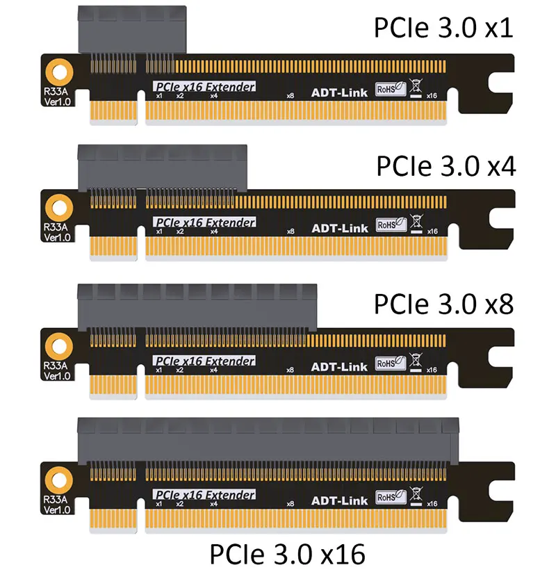
PCIe cards can always operate in PCIe slots with the same or more lanes than the card. For example, an x8 card can operate in a slot with x8, x16, or x32 lanes. Similarly, an x1 card can operate in any PCIe slot.
caveat:
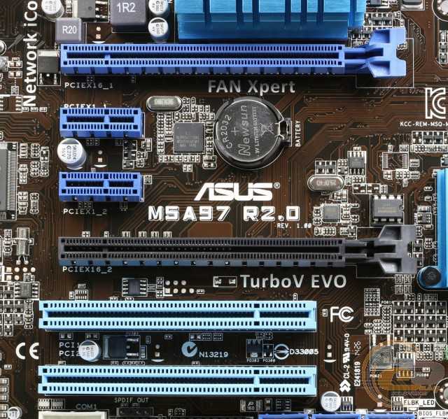
Sometimes, a PCIe slot operates with fewer data lanes than the mechanical slot-type indicates. For example, sometimes a motherboard manufacturer will use an x16 mechanical slot even though the data connection is only x8. In these cases, the higher-bandwidth card still may work (for example, an x16 card in an x16 slot with only x8 connection), if the card doesn’t require that extra bandwidth. The following image shows the PCI connections of the motherboard used in DuroPC’s RAC355. Notice ‘SLOT 1/5’ are PCIe x16 slots but only have an x8 connection. Similarly, notice how ‘SLOT 7’ uses an x8 slot but only has an x4 connection. (Click the image to see a larger version.)
Tagged on: PCI express, PCIe, PCIe x1, PCIe x16, PCIe x4, PCIe x8
|
|
|
|
|
Categories
Main Menu
Shopping Cart
There are no items in your shopping cart.
|
1. Introduction
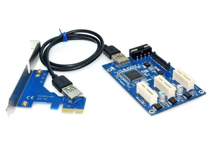
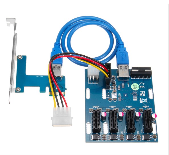
Number of our customers, interested in using this product, asked technical details. The xprs-px-x16 allows using of a PCI Express -x16 card, through -x1 link and cables. In general, one -x16 card, has 16 transmit and 16 receive pairs/lines. One -x1 card, has 1 transmit and 1 receive pair/line. Theoretically a -x16 card has to be 16 times faster than one -x1 card. PCI Express interface allows the work of a card, using the smaller number of transmit/receive pairs. This article compares the speed difference when the same -x16 card works using all 16 transmit/receive pairs, and when the card works using 1 transmit/receive pair. 2. Way of testing
(click on image to enlarge)The above image is a very simplified representation of mounting. A desktop motherboard is normally mounted in a box, hooked to a power supply … etc. The image below shows the same video card mounted on our
The above image is a also simplified representation of mounting. The xprs-px-x16 product has to be connected to a power supply in order to power on the PCI Express -x16 card. 3. Cards and tests
As a result of a web search for doing a benchmark test on a video card, we picked 2 tests:
The Freestone-Group test software (image above) is only for benchmarking video cards and gives a single score as the end result. The Passmark test software (image below) is for general benchmarking of a system, includes 2D and 3D tests for video cards, and gives separate scores for the each of the sub-tests.
4. Test results
Card -x16 -x1 Difference '8400' 44 40 9% 'gt 430' 238 231 2. The Freestone-Group mix of tests like the above show a very small difference between -x16 and -x1 mode. The Passmark test gives these scores for ‘8400’ card: Test -x16 -x1 Difference Graphics 2D - Solid Vectors: 0.9 0.9 0 Graphics 2D - Transparent Vectors: 0.9 0.8 11.1% Graphics 2D - Complex Vectors: 87.1 84.1 3.4% Graphics 2D - Fonts and Text: 36.3 28.8 20.6$ Graphics 2D - Windows Interface: 14.0 11.2 20.0% Graphics 2D - Image Filters: 92.3 88.4 4.2% Graphics 2D - Image Rendering: 202.2 141.5 30.0% Graphics 3D - Simple: 130.5 83.1 36.3% Graphics 3D - Medium: 50.6 34.4 32.0% Graphics 3D - Complex: 14.7 2.3 84.3% !!! Graphics 3D - DirectX 10: 0.9 0.9 0 2D Graphics Mark: 157.7 135.7 13.9% 3D Graphics Mark: 117. The Passmark test gives these scores for ‘gt 430’ card: Test -x16 -x1 Difference Graphics 2D - Solid Vectors: 1.0 1.0 0 Graphics 2D - Transparent Vectors: 1.0 1.0 0 Graphics 2D - Complex Vectors: 91.4 77.4 15.3% Graphics 2D - Fonts and Text: 36.1 35.5 1.6% Graphics 2D - Windows Interface: 14.0 14.0 0 Graphics 2D - Image Filters: 92.6 92.4 0.1% Graphics 2D - Image Rendering: 203.7 203.1 0.3% Graphics 3D - Simple: 406.5 396.9 2.3% Graphics 3D - Medium: 271.3 204.5 24.6% Graphics 3D - Complex: 16.0 4.0 75.0% !!! Graphics 3D - DirectX 10: 7.4 4.9 33.7% 2D Graphics Mark: 162.1 156.0 3.7% 3D Graphics Mark: 460.0 337.5 26.6%
A large difference appears for the Complex 3D Graphics test. However the larger the video memory is and the better/faster the GPU — the gap between -x16 and -x1 modes gets smaller. Conclusion — a PCI Express -x16 card placed in ‘-x1’ mode is getting most of the performance, and may be good enough solution in case of using a peripheral card outside of a computer system, through a cable. 5. DIY (do-it-yourself) testing
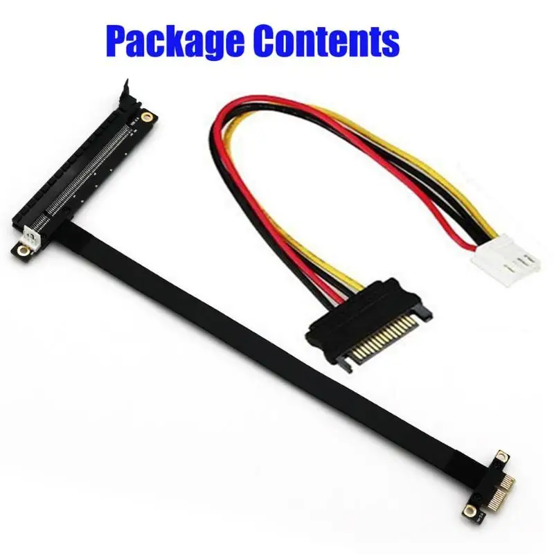
If you are curious about what the difference is between -x16 and -x1 modes for your video cards, there is a way to find this. The PCI Express connectors have compatible pin-outs — with the signals on the pins on the -x1 connector identical to the respective pins for the part of the -x16 connector. In practice this means that you can plug one -x1 card into a -x16 connector an it will still work.
The opposite is also true — using a tape, you can cover the additional pins of one -x16 card, and leave exposed only pins matching -x1 connector.
When you plug a -x16 video card prepared in such way in a motherboard, it will be forced to operate in -x1 mode. Then you can run some of the above tests or any other test you like. After testing, when the tape is removed, please make sure the pins on the -x16 card are cleaned with alcohol or other solutions.
|
Quick Store Search
Currencies
Account Menu
Popular Pages
|
 -x1 with PCI Express video cards
 9%
9%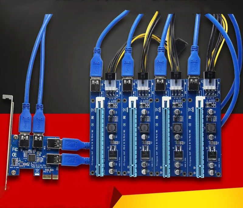 9 65.7 42.2%
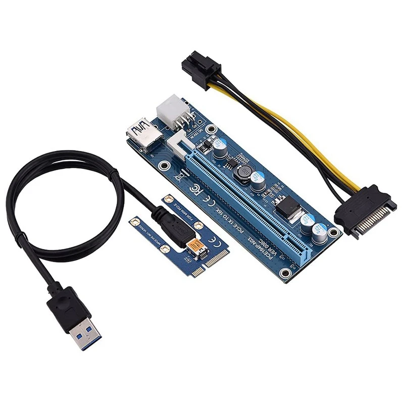
NVMe drives in different modes of operation of the PCI Express interface:
Test methodology for
drives of the 2016 sample
) will answer: of course PCIe 3.0 x4! True, with the justification, he is likely to have difficulties. At best, we get the answer that such drives support PCIe 3.0 x4, and the interface bandwidth matters. It has something, but all the talk about it began only when it became crowded for some drives in some operations within the framework of the «regular» SATA. But between its 600 MB/s and the (equally theoretical) 4 GB/s PCIe 3.0 x4 interface is just an abyss filled with a lot of options! What if one PCIe 3.0 line is enough, since it is already one and a half times more than SATA600? Fuels are added to the fire by controller manufacturers who threaten to switch to PCIe 3.0 x2 in budget products, as well as the fact that many users do not have such and such. More precisely, theoretically there are, but you can release them only by reconfiguring the system or even changing something in it, which you don’t want to do. But I want to buy a top-end solid-state drive, but there are fears that there will be no benefit from this at all (even moral satisfaction from the results of test utilities).
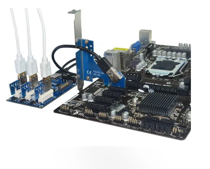
But is it true or not? In other words, is it really necessary to focus exclusively on the supported mode of operation — or is it still possible in practice to sacrifice the principles of ? That is what we decided to check today. Let the check be quick and not claiming to be exhaustive, but the information received should be enough (as it seems to us) at least to think … In the meantime, let’s briefly get acquainted with the theory.
PCI Express: current standards and their bandwidth
Let’s start with what PCIe is and how fast this interface works. Often it is called a «bus», which is somewhat ideologically incorrect: as such, there is no bus to which all devices are connected. In fact, there is a set of point-to-point connections (similar to many other serial interfaces) with a controller in the middle and devices attached to it (each of which can itself be a next level hub).
The first version of PCI Express appeared almost 15 years ago. Orientation for use inside a computer (often within the same board) made it possible to make the standard high-speed: 2.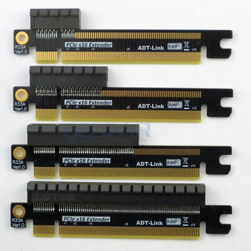 5 gigatransactions per second. Since the interface is serial and full duplex, a single PCIe lane (x1; actually an atomic unit) provides data transfer at speeds up to 5 Gbps. However, in each direction — only half of this, i.e. 2.5 Gb / s, and this is the full speed of the interface, and not «useful»: to improve reliability, each byte is encoded with 10 bits, so the theoretical bandwidth of one PCIe line 1.x is approximately 250 MB/s each way. In practice, it is still necessary to transfer service information, and as a result, it is more correct to talk about ≈200 MB / s of user data transfer. Which, however, at that time not only covered the needs of most devices, but also provided a solid supply: suffice it to recall that the predecessor of PCIe in the segment of mass system interfaces, namely the PCI bus, provided a throughput of 133 MB / s. And even if we consider not only mass implementation, but also all PCI options, then the maximum was 533 MB / s, and for the entire bus, i.e. such a PS was divided into all devices connected to it.
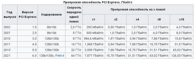 Here, 250 MB / s (since PCI usually gives full, not useful bandwidth) per line — in exclusive use. And for devices that need more, the possibility of aggregating several lines into a single interface was initially provided, in powers of two — from 2 to 32, i.e. the x32 version provided by the standard in each direction could already transmit up to 8 GB / s. In personal computers, x32 was not used due to the complexity of creating and breeding the corresponding controllers and devices, so the variant with 16 lines became the maximum. It was used (and is still used) mainly by video cards, since most devices do not need so much. In general, a considerable number of them and one line is enough, but some successfully use both x4 and x8: just on the storage topic — RAID controllers or SSDs.
Time did not stand still, and about 10 years ago, the second version of PCIe appeared. The improvements were not only about speeds, but a step forward was also taken in this regard — the interface began to provide 5 gigatransactions per second while maintaining the same coding scheme, i.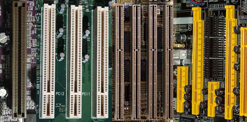 e., the throughput doubled. And it doubled again in 2010: PCIe 3.0 provides 8 (instead of 10) gigatransactions per second, but the redundancy has decreased — now 130 is used to encode 128 bits, and not 160, as before. In principle, the PCIe 4.0 version with the next doubling of speeds is already ready to appear on paper, but in the near future we are unlikely to see it massively in hardware. In fact, PCIe 3.0 is still used in many platforms in conjunction with PCIe 2.0, because the performance of the latter is simply … not needed for many applications. And where it is needed, the good old method of line aggregation works. Only each of them has become four times faster over the past years, i.e. PCIe 3.0 x4 is PCIe 1.0 x16, the fastest slot in mid-zero computers. This option is supported by top SSD controllers, and it is recommended to use it. It is clear that if there is such an opportunity, a lot is not enough. And if she is not? Will there be any problems, and if so, which ones? This is the question we have to deal with.
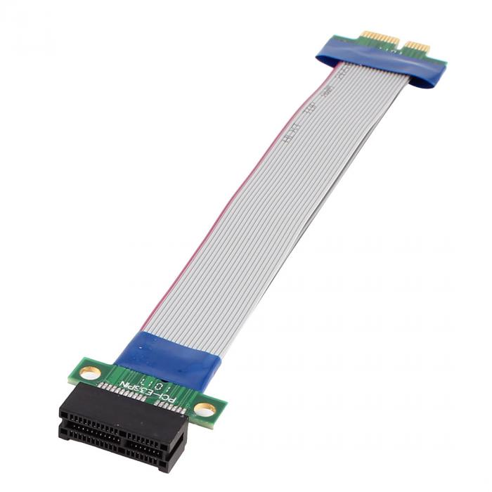
Test Method
Testing with different versions of the PCIe standard is easy: almost all controllers allow you to use not only the one they support, but also all earlier ones. It’s more difficult with the number of lanes: we wanted to directly test options with one or two PCIe lanes. The Asus H97-Pro Gamer board we usually use on the Intel H97 chipset does not support the full set, but in addition to the x16 “processor” slot (which is usually used), it has another one that works in PCIe 2.0 x2 or x4 modes. We took advantage of this trio, adding to it the PCIe 2.0 mode of the “processor” slot in order to assess whether there is a difference. Still, in this case, there are no extraneous “intermediaries” between the processor and the SSD, but when working with the “chipset” slot, there is: the chipset itself, which is actually connected to the processor by the same PCIe 2.0 x4. We could add a few more modes of operation, but we were still going to conduct the main part of the study on a different system.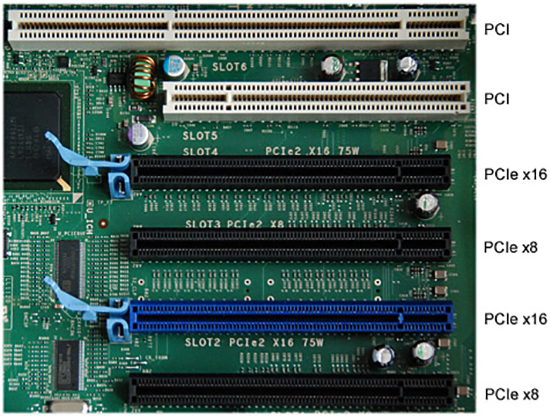
The fact is that we decided to take this opportunity and at the same time check one «urban legend», namely, the belief about the usefulness of using top processors for testing drives. So they took the eight-core Core i7-5960X — a relative of the Core i3-4170 usually used in tests (these are Haswell and Haswell-E), but which has four times as many cores. In addition, the Asus Sabertooth X99 board found in the bins is useful to us today by the presence of a PCIe x4 slot, which in fact can work as x1 or x2. In this system, we tested three x4 variants (PCIe 1.0/2.0/3.0) from the processor and chipset PCIe 1.0 x1, PCIe 1.0 x2, PCIe 2.0 x1 and PCIe 2.0 x2 (in all cases, the chipset configurations are marked in the diagrams with the icon (c)). Does it make sense now to turn to the first version of PCIe, given the fact that there is hardly a single board that supports only this version of the standard and can boot from an NVMe device? From a practical point of view, no, but to check a priori the expected ratio of PCIe 1. 1 x4 = PCIe 2.0 x2 and the like, it will come in handy for us. If the test shows that the bus scalability corresponds to the theory, then it does not matter that we have not yet been able to obtain practically significant ways to connect PCIe 3.0 x1 / x2: the first one will be identical to just PCIe 1.1 x4 or PCIe 2.0 x2, and the second — PCIe 2.0 x4 . And we have them.
In terms of software, we limited ourselves only to Anvil’s Storage Utilities 1.1.0: it measures various low-level characteristics of drives quite well, but we don’t need anything else. On the contrary: any influence of other components of the system is extremely undesirable, so low-level synthetics have no alternative for our purposes.
We used a Patriot Hellfire with a capacity of 240 GB as a «working body». As it was found during testing, this is not a performance record holder, but its speed characteristics are quite consistent with the results of the best SSDs of the same class and the same capacity. Yes, and there are already slower devices on the market, and there will be more of them. In principle, it will be possible to repeat the tests with something faster, however, as it seems to us, there is no need for this — the results are predictable. But let’s not get ahead of ourselves, but let’s see what we got.
Test results
When testing Hellfire, we noticed that the maximum speed on sequential operations can only be «squeezed» out of it by a multi-threaded load, so this should also be taken into account for the future: the theoretical throughput is theoretical, that the “real” data obtained in different programs under different scenarios will depend more not on it, but on these very programs and scenarios — in the case, of course, when force majeure circumstances do not interfere 🙂 Just such circumstances we are now we observe: it was already said above that PCIe 1.x x1 is ≈200 MB / s, and this is exactly what we see. Two PCIe 1.x lanes or one PCIe 2.0 is twice as fast, and that’s exactly what we’re seeing. Four PCIe 1.x lanes, two PCIe 2.0 lanes, or one PCIe 3.0 lane is twice as fast, which was confirmed for the first two options, so the third is unlikely to be different. That is, in principle, scalability, as expected, is ideal: the operations are linear, Flash copes with them well, so the interface matters. The Flash Stops handles well on PCIe 2.0 x4 for writing (so PCIe 3.0 x2 will do). Reading «may» more, but the last step already gives one and a half, and not two (as it potentially should be) increase. We also note that there is no noticeable difference between the chipset and processor controllers, and also between the platforms. However, LGA2011-3 is a little ahead, but only a little.
Everything is smooth and beautiful. But templates do not tear : the maximum in these tests is only a little more than 500 MB / s, and even SATA600 or (in the appendix to today’s testing) PCIe 1.0 x4 / PCIe 2.0 x2 / 9 is quite capable of this0042 PCIe 3.0 x1 . That’s right: do not be afraid of the release of budget controllers for PCIe x2 or the presence of only so many lines (and the version of the 2.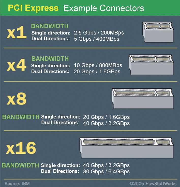 0 standard) in the M.2 slots on some boards, when more is not needed. Sometimes so much is not needed: the maximum results are achieved with a queue of 16 commands, which is not typical for mass software. More often there is a queue with 1-4 commands, and for this you can get by with one line of the very first PCIe and even the very first SATA. There are overheads and such, though, so a quick interface is useful. However, too fast — perhaps not harmful.
And in this test, platforms behave differently, and with a single command queue, fundamentally differently. The “trouble” is not at all that many cores are bad. They are still not used here, except perhaps one, and not so much that the boost mode unfolds with might and main. So we have a difference of about 20% in the frequency of the cores and one and a half times in the cache memory — in Haswell-E it operates at a lower frequency, and not synchronously with the cores. In general, the top platform can only be useful for kicking out the maximum «yops» through the most multi-threaded mode with a large command queue depth.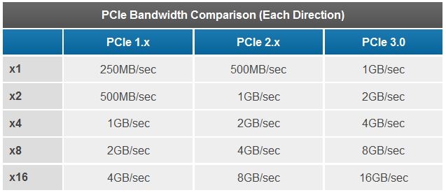 The only pity is that from the point of view of practical work, this is a very spherical synthetic in a vacuum 🙂
On the recording, the state of affairs has not fundamentally changed — in every sense. But, funny, on both systems, the PCIe 2.0 x4 mode in the “processor” slot turned out to be the fastest. On both! And with multiple checks/rechecks. Here you can’t help but wonder if needs these new standards of yours, or it’s better not to rush anywhere at all…
When working with blocks of different sizes, the theoretical idyll breaks down to the fact that increasing the speed of the interface still makes sense. The resulting numbers are such that a couple of PCIe 2.0 lanes would be enough, but in reality, in this case, the performance is lower than that of PCIe 3.0 x4, albeit not at times. And in general, here the budget platform «scores» the top one to a much greater extent. But just such operations are mainly found in application software, i.e. this diagram is the closest to reality. As a result, there is nothing surprising that thick interfaces and trendy protocols do not give any “wow effect”. More precisely, those moving from mechanics will be given, but exactly the same as any solid-state drive with any interface will provide it.
Total
To make it easier to perceive the picture of the hospital as a whole, we used the score given by the program (total — for reading and writing), normalizing it according to the «chipset» mode PCIe 2.0 x4: at the moment it is the most widely available, since found even on LGA1155 or AMD platforms without the need to «offend» the graphics card. In addition, it is equivalent to PCIe 3.0 x2, which budget controllers are preparing to master. And on the new AMD AM4 platform, again, this particular mode can be obtained without affecting the discrete video card.
So what do we see? The use of PCIe 3.0 x4, if possible, is certainly preferable, but not necessary: it brings literally 10% additional performance to middle-class NVMe drives (in its initially top segment). And even then — due to operations, in general, not so often encountered in practice. Why is this option implemented in this case? Firstly, there was such an opportunity, but the pocket does not pull the stock. Secondly, there are drives and faster than our test Patriot Hellfire. Thirdly, there are such areas of activity where loads that are “atypical” for a desktop system are just quite typical. And it is there that the performance of the storage system is most critical, or at least the ability to make part of it very fast. But this does not apply to ordinary personal computers.
In them, as we can see, the use of PCIe 2.0 x2 (or, accordingly, PCIe 3.0 x1) does not lead to a dramatic decrease in performance — only by 15-20%. And this is despite the fact that in this case we limited the potential capabilities of the controller by four times! For many operations, this throughput is enough. One PCIe 2.0 lane is no longer enough, so it makes sense for controllers to support exactly PCIe 3.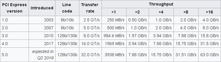 0 — and in the face of a severe shortage of lanes in a modern system, this will work well. In addition, x4 width is useful — even if there is no support for modern PCIe versions in the system, it will still allow you to work at normal speed (albeit slower than it could potentially), if there is a more or less wide slot.
In principle, a large number of scenarios in which the flash memory itself turns out to be the bottleneck (yes, this is possible and not only inherent in mechanics) leads to the fact that the four lanes of the third PCIe version on this drive overtake the first one by about 3, 5 times — the theoretical throughput of these two cases differs by 16 times. From which, of course, it does not follow that you need to rush to master very slow interfaces — their time has gone forever. It’s just that many of the features of fast interfaces can only be implemented in the future. Or in conditions that an ordinary user of an ordinary computer will never directly encounter in his life (with the exception of those who like to measure themselves with what they know).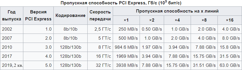 Actually, that’s all.
January 24, 2017
Andrey Kozhemyako
News
The first fast PCIe 5.0 SSD that won’t make noise or overheat? Aorus Gen5 10000
introduced February 6, 2023
Will fast expensive SSDs become pointless for gamers? DirectStorage equalizes three generations of drives
February 6, 2023
News section >
PCI Express x1, x8, x16 — what is it, PCI buses and devices, compatibility, pinout, PCIe 2.0, 3.0, 4.0, throughput, controllers
PCI Express was «born» on July 22, 2002. Intel Corporation became its creator, on that day its technical documentation became available. Up to this point, at the development stage, the «bus» had the designation 3GIO (third generation input-output). These two names were branded by the PCI SIG (the organization that now promotes this standard).
PCIe is a high-performance point-to-point connection that has replaced the PCI bus (pronounced PSI).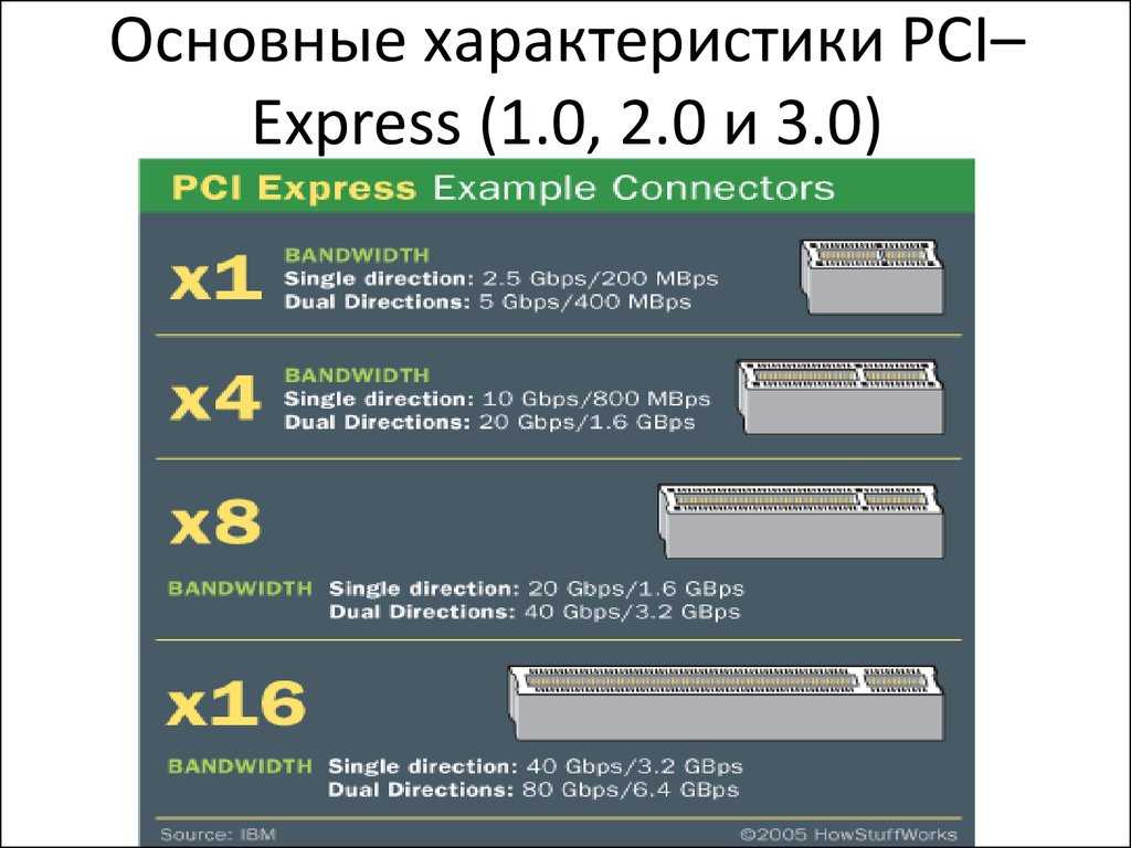 Physically, it differs in that does not use shared leased lines to communicate with the processor, but has its own dedicated lines for each connected device. The signal transmission voltage of is 0.8 volts. Each channel represents two physical conductors (four contacts). When broadcasting information, eight bits are encoded by ten, which gives good protection against interference.
Shares its common programming model with its predecessor. For data transfer, which in this case is carried out sequentially, a physical protocol with a large bandwidth is used. Used to connect high performance peripherals. The role of a local data exchange channel was assigned to the pseudobus.
Differences between PCI Express and PCI
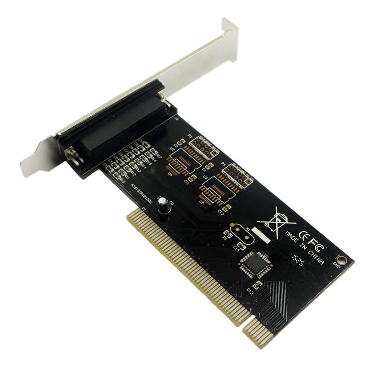
PCI is primarily a bus, that is, a common channel shared by all devices connected to it. And PCI Express — for each device has its own paths, which are physically designed. Continuity of the digital structure of information transfer makes it easy to adapt existing products that were previously produced to work with an old tire.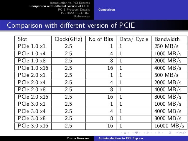 In production, it is sufficient to make minor adjustments to the design and you can produce the same variety, but with a new interface.
Principle of operation, compatibility
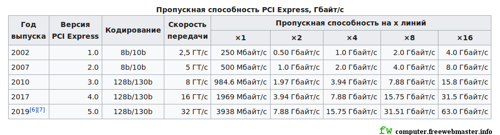
Being a two-way connection, the connection transmits data serially to in packet mode. Throughput depends on the implementation in each case. There are one (1x), two or more PCI Express lanes (2X, 4X, 6x, 8x, 12x, 16x, 32x), which determines the length of the slot on the motherboard. It is typical that the equipment is capable of working with any of them, but expansion cards adapted for serious speeds cannot physically fit into less productive slots, simply not matching in size. Although, on the contrary, less productive expansion boards with short contact groups easily fit into large ones and work correctly.
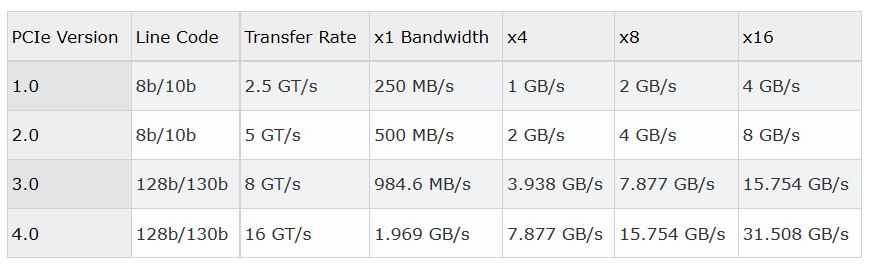
In the table we have given a summary table of the ratio of the number of lines and throughput :
Several bus specifications are now available :
- PCI Express 1.
 0 and 1.1. The first and least productive solutions that are practically not used now. They are stored on old boards that are still in use.
 - 2.0. All performance-defining qualities have been reworked and improved, logical protocols have been improved, communication management has been comprehensively optimized, auto-detection of plug-ins has been improved.
- External cable specification PCIe . Allows you to connect equipment with a cable up to 10 m long.
- 2.1. An intermediate version of 2.0 with some advanced features that preceded the introduction of 3.0.
- 3.0. 8 gigatransactions per second (GT/s) is now available with the new 128b/130b encryption system. Thus, the difference between pci 2.0 and 3.0 is in encryption and data transfer speed.
- 4.0. The standard was recently approved — 10/5/2017. Compared to the previous one, the speed is doubled.
 Individual indicators associated with virtualization have increased, the transmission of data packets has been optimized.
 - 5.0. Tentatively, the release is scheduled for winter-spring 2019. Expanded support for applications that visualize virtual reality has been announced.
Existing connectors and types of ports
There are many connection ports for the interface. Consider some of the most common of them:
- MiniPCI-E (M.2). Common bus for some of the most common computer protocols and x1 and x4 PCIe interface devices.
- ExpressCard. Similar connector, but with a bus pin for x1 PCIe only.
- AdvancedTCA, MicroTCA — ports for communication equipment.
- MobilePCIExpressModule (MXM) — NVIDIA development for connecting video cards.
- StackPC — for creating supercomputers, allows you to scale computing devices.
How to find out the PCI Express version on the motherboard
Usually written next to the slot on the motherboard, but may be written elsewhere.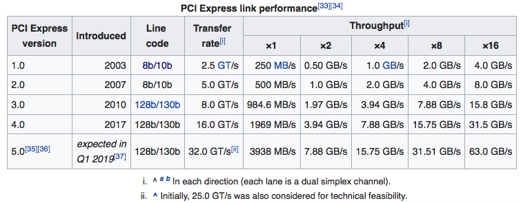 Still often is written on the packaging of motherboard and indicated in the manual. You can go to the official website and enter the serial number of the motherboard into the search, or try to search for the specification by name and revision (variety).
Hardware examples
The most common peripherals for the highest performance x16 slots are video cards and ssd drives. Not rare are controllers such as additional USB, SATA and similar high-speed ports or various adapters, such as sound, music cards, Wi-Fi modules.
video card
HDD
Wireless adapter
Pinout PCI Express
It is easier to exhaustively show the location of the outputs of the communication lines using the example of the lines of the largest and fastest port.
PCI-Express 16x Slot Pinout Device:
The PCIe connection has proven itself.