Best Fan Control Software for Windows
Need a program to help you gain more control over the fans in your computer? In this post, we’ve highlighted four fan control programs to help you find the right option for your needs.
When your computer’s fans go haywire every time you start Chrome, or when you’re playing your favorite game, it’s a sign that your fans need to be reined in. Luckily there are programs out there that will help you get your fans to behave in a manner you want them to. Fan control software will give you the ability to control your PC’s fans based on your system’s temperature.
In this article, we cover four Windows software tools that help you manage your fan speeds. Some of the programs have other features as well, including system monitoring, warnings for failing drives, and even overclocking tools, to name a few.
So, if you’re looking for a program that can help you customize your fan settings (or even more) check out our recommendations below.
Fan Control Software
1. Fan Control
2. EasyTune 5
3. Argus Monitor
4. HWMonitor
5. Zotac FIRESTORM
6. SpeedFan
1. Fan Control
A somewhat newer Fan Control application that many PC enthusiasts are turning to is Fan Control. Fan Control was created by an independent developer and is perhaps the most robust, intuitive, and easy-to-use fan control software currently available.
With fan control, you can track your CPU, GPU, motherboard, and storage device temperatures, fully control all of the fans in your system (including the individual fans on your graphics card), and, of course, create custom fan curves.
The software is completely free to use but the developer (Rem0o on GitHub) does accept donations. And, considering that Rem0o was able to create a truly all-in-one fan control program where many other professional developers have come up short, it wouldn’t hurt to throw a donation their way.
You can get Fan Control here.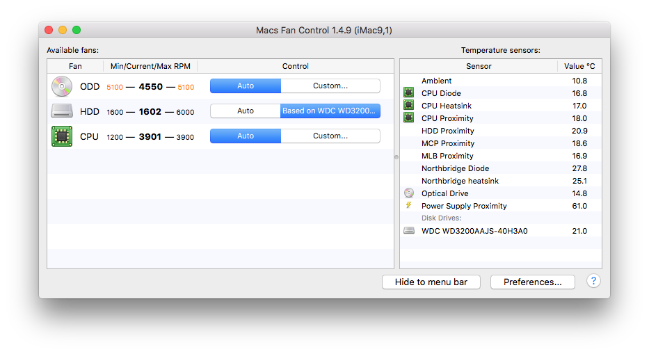
2. EasyTune 5
With EasyTune 5, you get more than just a tool to monitor and control your fans’ speeds. The program also has a bunch of other useful features at your disposal that you probably didn’t know you needed.
The EasyTune 5 feature we’re most concerned about here is the Smart-Fan control. This feature gives you direct control over your CPU cooler’s fan. With the Easy Mode, you can configure this feature with ease.
Also Read: The Best CPU Coolers Right Now
You can also set the speeds of your fans to correlate with your CPU’s temperature. Just keep in mind that you don’t want to set a threshold that is too high, as doing so could prevent your CPU from getting the airflow it needs to operature correctly.
If you’re also looking for a program that can help you overclock your CPU, EasyTune 5 can assist you there as well. You can get much more power and performance out of your CPU and memory with the CPU Intelligent Accelerator (C.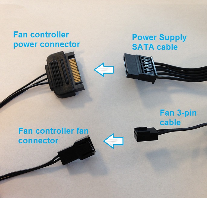 I.A.) and Memory Intelligent Booster 2 (MIB2) features. These features can be found in the program’s Advanced Mode.
You can get EasyTune 5 here.
3. Argus Monitor
If you’re looking for a lightweight fan control program, Argus Monitor is probably your best bet. It has a small memory footprint and gives you full control over your fans’ speed, and it also monitors the temperature and health of your CPU and hard drives and SSDs.
It sounds like a lot of features to get from a program that runs as a background task. But that’s what makes Argus stand out. In addition, this tool displays and controls the fan speed of modern NVIDIA and AMD graphics cards. This is a particularly useful feature for gamers.
Argus Monitor can also help you identify if there are early warning signs that your hard drive or SSD is failing. The program warns you (with 70 percent accuracy) that your drive is failing. This gives you ample time to get a new one and transfer all your important files from the old drive.
With an easy to configure interface, this is a tool that has all the features you need to run your PC smoothly. The only drawback is that it’s only free to try for 30 days. If you want to keep using it after 30 days, you’ll need to purchase a license.
You can get Argus Monitor here.
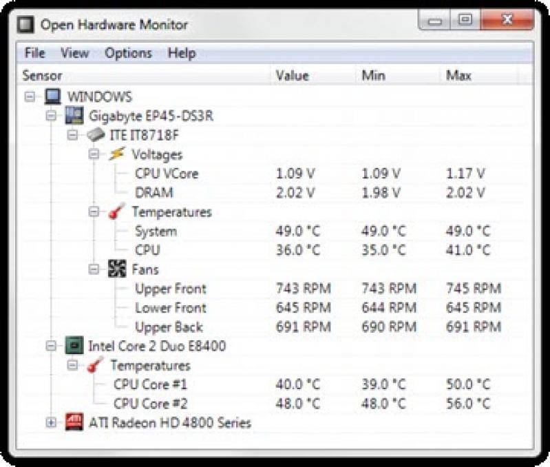
4. HWMonitor
HWMonitor is another program that has been around for quite a while. And during that time, it has distinguished itself and cultivated a userbase that keeps growing. HWMonitor does everything the other programs do and then some.
Once installed, it monitors your system’s main sensors. This includes voltages, temperatures, and fan speeds. It also reads your drive’s S.M.A.R.T. vital stats and even keeps a watchful eye over your video card.
The program provides a straightforward way to control your system’s fans (including your CPU cooler’s fan). And if you want to keep track of your PC’s power usage, this tool logs the motherboard’s voltage and CPU voltage, as well as the overall system’s power consumption in watts.
The one downside of HWMonitor, though, is that the user interface is a bit clunky. It might take you a while to get familiar with the columns of numbers in front of you. But once you know your way around, you’ll never want to use another application.
You can get HWMonitor here.
5. Zotac FIRESTORM
Zotac’s FIRESTORM is yet another handy program that can serve as a fan speed controller and overclocking utility. Zotac is no stranger to the industry, as they sell both gaming desktops and graphics cards. So, it’s safe to say that they know what they’re doing.
Perhaps the standout feature of FIRESTORM is its simple and easy-to-use interface. With FIRESTORM you can overclock your GPU, set custom fan curves, change your graphics card’s RGB lights, and monitor its performance.
It’s important to note, though, that FIRESTORM will not give you CPU fan control. It will only give you control over your graphics card and its fans.
But, if you need to control the fan speed of your graphics card, this is an excellent program to get.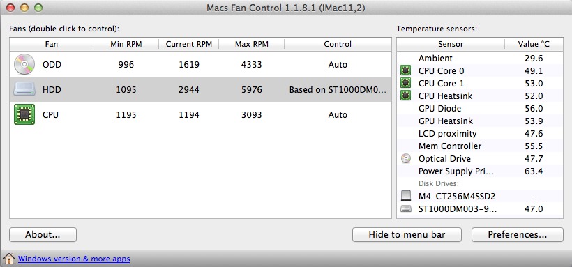
You can get Zotac FIRESTORM here.
6. SpeedFan
SpeedFan is one of the oldest tools out there. Its history is almost as old as Windows itself. The first version was released around the time Windows 9x was considered the cutting edge in operating systems. It’s that old.
Having a long history is usually a good thing. Especially for a customizable program with a clean user interface that is compatible with all versions of Windows. However, SpeedFan hasn’t been updated since 2015 and so it isn’t the best option for newer systems.
So, while SpeedFan may have once been the best fan speed control programs available, it’s lack of updates and the emergence of better options drops it to the bottom of this list.
You can get SpeedFan here.
While there are a ton of different CPU temperature monitor programs out there as well as plenty of other hardware monitoring applications, there aren’t nearly as many options for fan control software. However, the six options listed above will help you gain better control over the fans in your system so that you can reduce noise levels and improve temperatures.
10 Best Fan Control Software For Windows
The fans inside your computer keep the component and the system cool. Generally, they spin at different RPMs (Rotation Per Minutes) depending on the load on your system. But sometimes, the fans might spin at a high RPM by default, which can cause the system to get noisy.
However, you can control the rate at which they spin using fan control software.
A good fan control application makes it easier to tune the CPU and GPU fans for maximum performance with minimum noise. Keeping this in mind, we have listed some of the best fan control software that you can use.
MSI Afterburner (For Windows)
MSI Afterburner is free software that allows you to overclock your computer. Along with controlling fan speed, it can display memory usage, CPU/GPU temperature, FPS (Frames Per Second), GPU voltage, and frequency in real-time. Along with this, MSI Afterburner is free and works with almost any graphics card, AMD, or Nvidia.
Users can set up to 5 profiles of fan speed settings. This can be really helpful, as you don’t need to tweak multiple fan settings to keep the performance maximum. You can also create your own fan curve.
Note: A fan curve is a chart visualization of fan speed and temperature. Using the chart, you can set the fan speed according to the temperature. Follow these steps to create your own fan curve.
Go to Options, then the “Fan” tab to activate manual fan control in MSI Afterburner. Click “Enable user-defined software automatic fan control.” Here, you can create your own fan curve.
Corsair iCUE (For Windows)
Corsair iCUE is software that manages all Corsair products on your computer. This software monitors the real-time temperature, creates custom lighting effects to alert you when temperatures rise, and also controls fan curves to change fan speeds.
Corsair iCUE allows you to synchronize the RGB lighting on all of your compatible corsair devices. There are four waves of light to choose from: Rainbow, Yellow, Rain, and Visor.
iCUE also controls the performance of your system depending on your activity. By default, it has three modes: Quiet, Game, and Movie. You can create a quiet mode for working, a performance mode for gaming, and more.
One downside to iCue is that it cannot link with all devices. You can check out Corsair’s support page that lists all the hardware compatible with iQUE.
FanControl (For Windows)
FanControl is one of the best free fan control applications on the market. This application was developed by a single developer, Remi Mercier. This simple but elegant application controls all your fans, including case fans. However, you cannot use the application to control the colors on your RGB fans.
The application’s user interface is very clean, and icons are not clustered with each other. FanControl is an easy-to-use application that even novice users can easily navigate within the application. However, its installation can be a little tricky. Remi also has video instructions for the setup process.
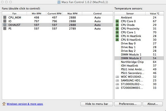
Macs Fan Control (For Mac)
If your Mac is too noisy or overheats too much, the Macs Fan Control software is the best free solution. Macs Fan Control is suitable for fan monitoring and controlling software for Mac. It is an easy-to-use application that optimizes fan speed for maximum cooling efficiency. The application’s simple slider user interface enables quick fan speed adjustments.
When you open the application, it will display all the fans on one side and components such as temperatures on the other. To change the mac fan speed, go to the “Custom” tab and adjust the CPU fan or intake fan speed with the slider before clicking “OK.” On Preference, you can also see users’ preferred settings around the world.
SpeedFan (For Windows)
SpeedFan is an old but impressive application that monitors system temperature and provides a detailed report to the user. This free software also adjusts fan speed, voltages, HDD temperature. SpeedFan displays the temperature of hard drives using SMART sensors.
Note: SMART (Self-Monitoring, Analysis, and Reporting Technology) is a hard disk monitoring system that provides information on a drive’s status.
Unfortunately, because SpeedFan is an outdated application, it does not receive updates. SpeedFan does not support the latest model motherboard. It will most likely work if you have an older motherboard.
Zotac Firestorm (For Windows)
Zotac Firestorm is free software that offers you complete control over any ZOTAC component connected to the motherboard. You can manage RGB colors and control fan speed on all ZOTAC components connected to your computer. Besides this, we can also use the Zotac Firestorm to overclock the graphics card.
You can choose three settings to control your fan speed: Auto, Manual, and Advanced. Auto is the default setting.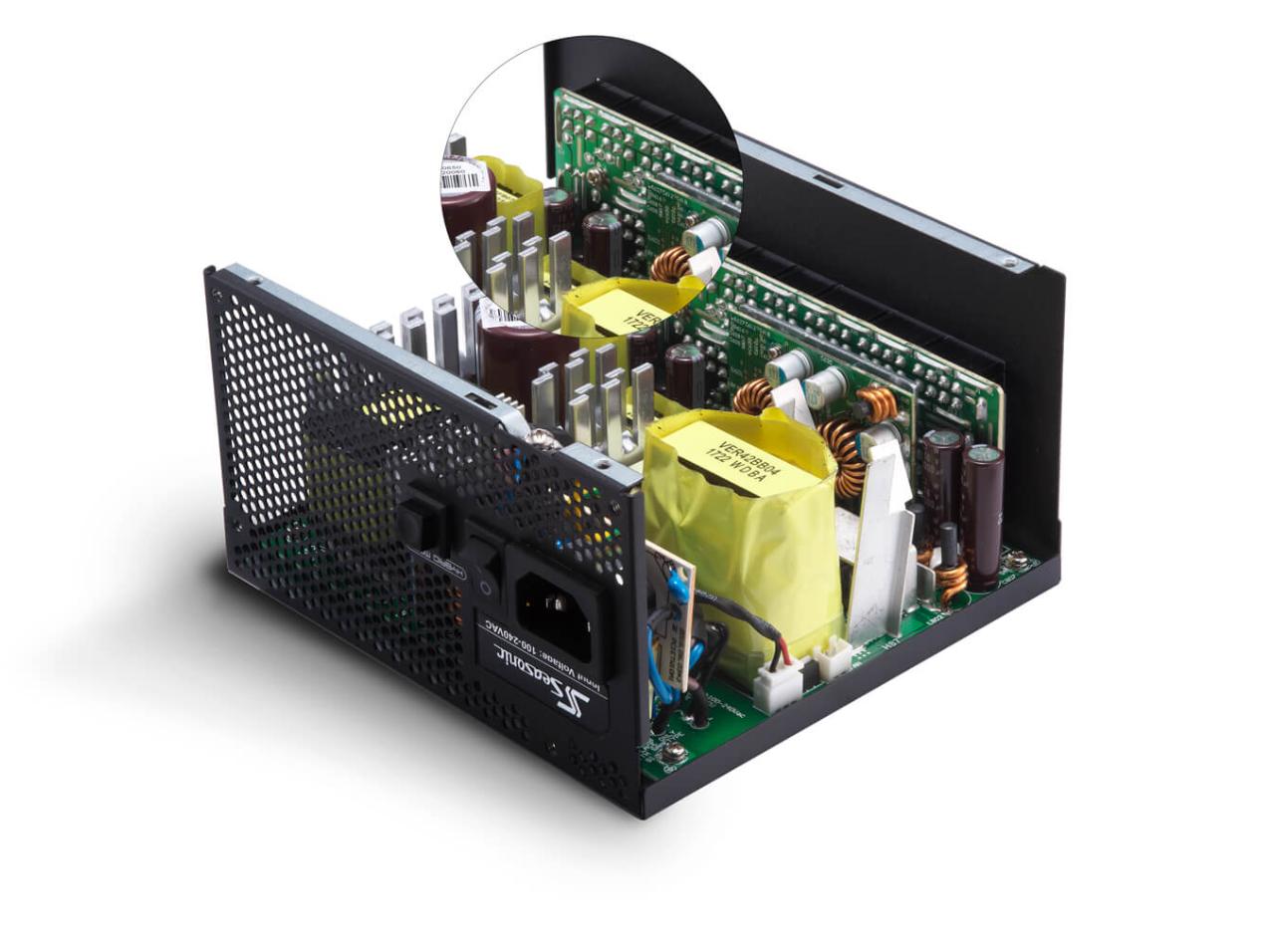 Manual settings allow you to set the speed (in%) according to your need. The fan will spin at the set speed regardless of the graphics card’s temperature. Selecting the Advanced settings, you can set the fan curve according to your need.
With a few clicks, you can extract more performance and low noise from any ZOTAC graphic card. One disadvantage to Zotac Firestorm is you cannot control the RPM of the case fans.
Argus Monitor (For Windows 10 and Higher)
This german software can control every case fan connected to the motherboard. You can also make your own fan curve configuration. Like SpeedFan, it uses SMART sensors to display HDD/SSD temperatures. Including all this, it also displays real-time CPU/GPU temperature.
Argus Monitor also provides a sidebar gadget that shows all the hardware information like frequency, temperature, fan RPM, CPU usage, and CPU power. These values are color-coded and visible in the tray icons on the bottom-right of your screen. However, it’s one downside is, we cannot overclock our system using Argus Monitor.
ASUS AI Suite 3 (For Windows)
Using ASUS AI Suite 3, you can control all your ASUS hardware connected to your motherboard for free. Like in every fan control software, you can easily monitor frequency, voltage, CPU/GPU temperature. It also supports overclocking for Ryzen processors. But, overclocking through software is not an ideal choice.
Since the application is ASUS-specific, you can only control the fan speed of the ASUS graphic card. ASUS AI Suite 3 uses Fan Xpert 4 to manage all the fans connected to your motherboard. This also includes all case fans that are connected to the motherboard. But, you should have an ASUS motherboard to access this feature.
MSI Dragon Center (For Windows)
Using the Dragon Center, you can customize any MSI product connected to your motherboard. This includes monitoring all the stats (CPU/GPU temperature, frequency, voltage, etc.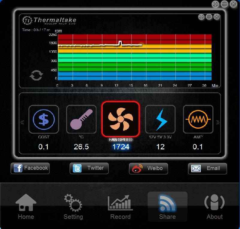 ) and fan control.
You can use this simple but free application to optimize the fan speed with one click using gaming mode.
The Dragon Center has three preset modes: Performance, Battery life, and Acoustic. Along with this, if you are on a laptop, you can find the cooler booster mode. This preset can get louder as the fans spin at their maximum RPM. If you are an MSI user and looking for simple software to control the GPU and CPU fans, the Dragon Center is the one for you.
Using BIOS Settings (Motherboard Setting)
Another way you can adjust the fan’s RPM is through the BIOS settings.
You can tweak your entire motherboard settings from the BIOS. Every motherboard has a section for monitoring your hardware, including controlling the CPU and case fan speeds. However, GPU fans are not adjustable using this method. Along with this, you can also overclock your computer from the BIOS.
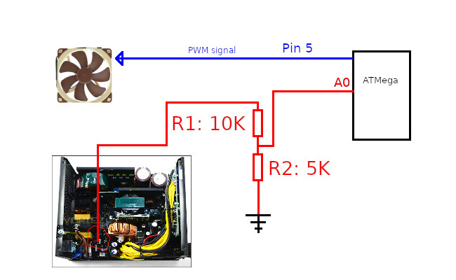
PSU fan control (“Weekend Design”)
Technician
0W cooling fan on immediately, permanently, and at full speed .
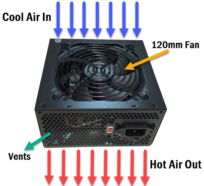 It makes wild noise and rages. The controller (Duet 3, firmware RRF 3.3) has a free temperature measurement channel and a free fan control channel. So why not use them?
Result : In the range of power take-off that interests me, the fan runs inaudibly, the power supply heats up insignificantly, the current temperature is under constant control:
This is printing with PLA plastic for an hour and a half, the table is heated to 65 degrees. He heated the table to 112 degrees for 30 minutes (set 120, but the design does not pull more than 112; that is, the table is constantly connected, 100% power). The fan speed has increased, the fan is barely audible, the steady temperature of the transformer is 45.7 degrees (according to the sensor). Palm to the body — the sensor does not lie.
More than a lot of books and photos. Photos removed to the very bottom …
Warnings :
- Rework is done in the power supply.
 Therefore, it is desirable that it be performed by a person who has the skills of installing electronic equipment.
 - Power supplies have different circuitry. And the Chinese, who copy the blocks, overclock them in different ways. In my (i.e., a very specific PSU) on my printer (i.e., quite specific current consumers), I see the point in controlling the temperature of the high-frequency transformer. In other cases, it is possible that other components (rectifier, inductor, or something else) will heat up more. So, it is possible (but not necessary) that the temperature sensor will need to be attached to something else.
How I did :
I took the temperature sensor (“drop”, 100K B3950) attached as a gift from the Chinese seller, lengthened its wires, insulated the connections, added heat shrink to the place that will pass through the hole in the PSU case and press with a fixing petal. This is a temperature sensor for a heating cube, the insulation of the wires must be heat-resistant. In any case, they must withstand the operating temperatures of the PSU with a margin. Crimped the terminals and put on the «mother» to connect to the controller. Hooked it to the «Temp 3» connector.
I cut off a piece from the edge of a paper clip (it took 2 minutes with a cutting disc on the engraver), straightened the curl on one edge completely (to go into the gap between the iron of the transformer and its coil). On the other side, he under-straightened and formed a small “wave” so that the drop sensor lay in its recess and did not tend to fly out to the left and right. Lengthwise, it won’t go anywhere.
I did not make a separate hole in the PSU case for wires, I passed a “drop” into the slot on the case. There is just a mounting hole with an M4 thread nearby — I screwed on an elastic “petal” (made from a contact from some old relay) and pressed the wire with it from accidental jerks.
The fan is left as is. On the farm, I don’t remember where a torn piece of cable came from with a rare “daddy” JST Xh3. 54 (you can cut such a connector from some old device along with a piece of the board and solder the wires to the contact pads; but I do not recommend soldering the wires directly to the bare pins — they are held in the plastic of the «dad» very weakly). At its other end, the adapter crimped the terminals and put on the “mother” to connect to the controller. The fan connector had to be unmounted; in this form, the fan wires passed into the slot of the PSU case from the inside to the outside. The connector is put on as it was (it is important not to confuse the polarity of connecting to the controller!). The fan in this power supply is rated for 12 volts. On my controller (Duet 3), the output voltage is switched by a jumper; switch Out 7, Out 8 and Out 9on 12V. I hook a fan on «Out 9».
I took this opportunity to cut out a stamped grate from the fan window, then I will put a 60mm grill grate here. I’ll put in an air filter. Or somehow combine the grate with the filter. The fan turned over and now it works to force air into the PSU (from the factory it is to be pulled out of the PSU).
Setting:
I add 4 commands to Config.g (forgive me, a German, for the crooked use of the English language):;
; Heaters
M308 S2 P»temp3″ A»PSU» Y»thermistor» T100000 B3950 ; configure sensor 2 as thermistor on pin temp3
M950 h3 C»nil» T2 ; create virtual Heater 2 with Sensor 2
; Fans
M950 F2 C»out9″ Q15000 ; create fan 2 on pin out9 and set its frequency
M106 P2 C»PSU» h3 L0.05 T43:47 B0.5 ; set fan 2 name and value. Thermostatic control is turned on for virtual heater h3
Let’s look at the commands in detail:
M308 command and its parameters
- S2 – create the “Sensor 2” temperature sensor and define it
- P “temp3” – assign the connection to the controller connector “Temp 3”
- Y»thermistor» — the sensor is of the «thermistor» type
- T100000 — resistance at 25 degrees Celsius, Ohm; for the thermistor «100K 3950» it is 100000
- B3950 — set the beta parameter of the thermistor; at the thermistor «100K 3950» it is equal to 3950.
9003 3 A «PSU» — Give alias «PSU» for this sensor
The M950 command (in the Heaters section) and its parameters assign to connect this heater no controller connector
M950 command (in the Fans section) and its parameters
- F2 – creating and configuring the fan «Fan2»
- C «out9» — the fan is connected to the controller connector «Out 9»
- Q15000 — control pulse frequency, Hz (by default in RRF 3.3 firmware it is 250 Hz)
The M106 command and its parameters
- P2 – for the “Fan2” fan, we determine that
- C»PSU» is its alias for graphics and controls
- h3 – it is engaged in thermostating the heater channel «Heater 2»
- L0.05 — when turned on, it operates at 5% power (5% of the control pulse width from the maximum) L0.05) in the range of 43..47 degrees, the power (pulse width) increases linearly up to 100% from 47 degrees and above works at 100% power impeller from its place and the beginning of its unwinding)
Now some more details and features of (to the extent of my knowledge and understanding. If I’m wrong, please correct me in the comments!).
- Control pulse frequency ( M950 parameter Q15000 ) is set to the upper limit of the audible range, 15kHz. At lower frequencies, you can still hear how the coils are switched (well, if you like, you can hear how the coil field kicks the impeller). But it is necessary to check with each specific fan how it starts and works. For example, my PSU fan also works at a frequency of 20 kHz, and my «snail» 5015 (blowing the printed part) refused to spin up steadily at such a frequency. Experiments (control frequency, start-up speed, full power time) can be carried out with commands from the console/terminal.
- M950 h3 (we create a heater) — without a heater in the RRF 3.3 firmware, the temperature control functionality does not work. Without the «C» parameter, you cannot create a heater. The parameter «C» nil «», strictly speaking, is intended to release the previously occupied controller port. There is a potential ambush here: if, after executing such a «C» nil «», you try to use the M950 command to access such a «freed» heater, things will end badly — an «Error» will be issued and the fan will stop.
 But, as one joke says: “Don’t do that!” With further settings, we do not refer to the heater. We in command M106 configure the temperature control channel for the h3 heater — it rolls without errors. In the end, you can assign any free port to this heater, even low-current ones — you are not going to connect any load to this output at all.
 - M106 T43:47 thermostat function; I first set T40:60 — and the fan started to start, and after 2 seconds it turned off. In idle mode (when the printer is in standby mode and all heaters and fans are off), my temperature slowly rises to about 41 degrees. At 40, the fan turns on, blows everything with room air, brings the temperature down to below 40 and turns off. And a minute later, the cycle repeats again. Is it necessary? So you yourself set these limits for your specific PSU and for the power consumption of your printer. The characteristic can and should be changed during experiments by executing the M106 command with its parameters directly from the console/terminal.
 And then at any time at any time. For example, you start printing with PETG plastic, the table will heat up to a temperature of 95 degrees; in the plastic loading macro you can change the function. Take out PETG, load nylon — in the plastic loading macro, you can change the function for even more difficult conditions.
 - In the command M308 , you can specify additional definitions for the temperature sensor, which will make its operation more accurate in the narrow temperature range of interest to us (20…100 degrees. Or even in an even narrower one – 40..70 degrees). But for this particular case, in my opinion, accuracy is enough.
Lovers of fire extinguishers and other enhanced security :
- My PSU has a protection element provided by the manufacturer (and I did not touch it): a KSD temperature sensor is attached to the input voltage rectifier bridge, which will stop the PSU operation, if anything.
- My PSU is designed for 600W, I take (according to my estimates) 240W from it.
 Well, okay, even 300W. It is generally considered that a headroom of 20% is more than enough. I have a power margin of 50%. That’s exactly my (specifically mine) BP was considered by several luminaries on Mysku; the thesis was put forward that this power supply does not really need a fan at all until 70..80% of the power is pumped from it. And no one objected to it. Taking current for half an hour to everything that came to my mind and my printer, I got a temperature of 45.7 degrees. BP must survive the temperature of this trance of 9 degrees without consequences for his health0 at least. In my setup, I will never get to this value.
 - Yes, there is a hotter part in my PSU. I know about it. But she is specially trained for that. And when the fan cools the trance, it cools her too.
- I now have the temperature of the transformer constantly before my eyes, dotted on the graph. And how are you?
Now what I don’t know and on what topics I hope to get advice:
- I didn’t understand something and what I did should have been done differently?
- Is there a more correct way to assign a heater without occupying a controller port than to specify «M950 Hn C»nil»»?
- Maybe it’s worth asking the firmware developers to provide such an option (temperature control channel without heater)? Is it interesting to anyone besides me?
For those who are interested in the idea but want more :
- Duet (at least Duet 3) works with 3-wire fans.
 You can attach a fan from some computer processor and control the speed of the impeller using the fan tachometer (usually a yellow wire). You can even attach a 4-wire fan and control it through its PWM control channel (usually it’s a blue wire; but you need to set the correct frequency of the control signal. As far as I remember, it’s 2 kHz).
 - If your controller works together with some kind of SBC (raspberry, orange or something else), then you can power that SBC from a separate low-current power supply unit and assign to the SBC all the functions for managing and controlling the main power supply unit (turning the power supply on and off through a solid state relay, PSU temperature measurement and PSU fan control).
Well pictures:
PSU Control
Follow author
Subscribe
Don’t want
13
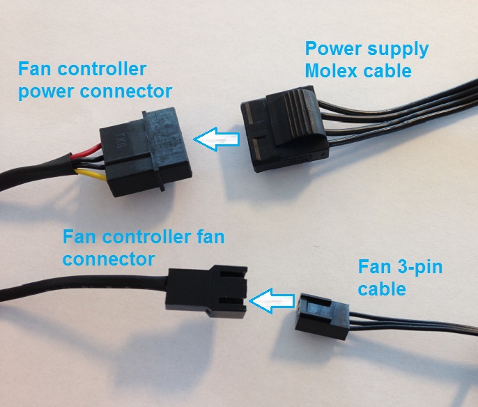
Using fan control boards from computer PSUs
Recently I went to visit a friend, and he sits and takes apart old power supplies from computers — he wants to see what they have inside. Elbow-deep hands are dirty, there is a column of dust, but at the same time the table is neatly covered with newspaper. It seems that this day will end with a general cleaning of the office…
I appeared just at the moment when the «autopsy showed» that using transformers for battery «charging» would not work. And all the interest immediately switched to fans with a control board, and, naturally, the question immediately arose “is it possible to apply this somewhere?” Well, suppose you can apply it, but for what? What is the purpose?..
We sat for a while, drank coffee, and discussed application options. In general, they agreed that I was taking the fans for experiments, and then we’ll see…
I didn’t postpone this matter for a long time, in the evening I started checking.
Control boards are different (marking GDP-002 94V-0 at fig. 1 and 3BS00195 at fig. structures, another PNP) and 2 power wires each, then the circuits should not differ much.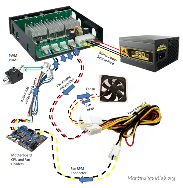 True, one has a thermistor, while the other does not — a yellow wire simply sticks out of the board, designated as «OPR» (perhaps it once went to the thermistor). The power leads are also signed, but you can also figure them out by color (black is “minus”, the other is “plus”).
Fig. 1
Fig. 2
First, a board with a thermistor was connected to the laboratory power supply. The fan started to rotate at about 10 V, there is almost no noise, the rotation speed is small, the air flow is weak. At 12 volts, the rpms didn’t increase much, the noise remained about the same. When checking the motor supply voltage, the tester showed 5 V.
Then a hot soldering iron was brought to the thermistor. After a few seconds, the fan speed increased sharply and it made a noticeable noise — the voltage on the engine became almost 12 V. When the soldering iron was removed and after 20-30 seconds, the speed drops sharply to a minimum value. It turns out that this scheme does not have a smooth speed control.
Another board was connected to the power supply. The fan started at 5.5 V, the rotation speed is low, there is no noise. When powered by 12 V, the speed increased slightly, the noise is weak, the voltage on the fan wires is 5 V.
about 12 V).
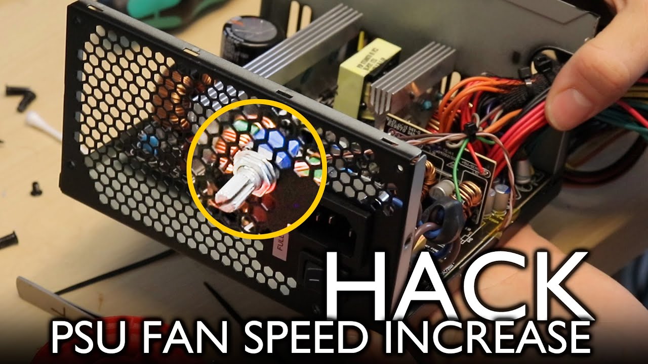
To check the possibility of smooth speed control, the yellow wire was soldered to the engine of a variable resistor with a resistance of 10 kOhm, and its extreme terminals to the “minus” and to the “plus” of the power supply ( fig.3 ). When the voltage on the engine is about +8.0 V, the engine starts to increase speed and already at +8.5 V it reaches its maximum.
Fig. 3
A diagram was drawn from this board ( fig. 4 ). In place of the resistor R2 is a zener diode for the same voltage as ZD1 (6.2 V).
Fig.4
The principle of operation of the circuit is simple — as long as the voltages at the inverse inputs of the comparators are lower than the voltages at their direct inputs, the comparators have a “high level” at the outputs and this keeps the transistor Q1 in the closed state, and Q2 in the open state. In the Q2 collector there is a resistor of such resistance that when the potentials are distributed between the resistor and the motor, 5 V “falls” on the latter. This voltage is the reference for the OP1.1 comparator. When the input voltage rises (point «OPP») to a level where the potential at the inverse input OP1.1 becomes greater than the level at its direct input, it should switch «to zero» and open transistor Q1, but this does not happen, since when opening Q1 immediately raises the level of the reference voltage and there is some unstable state with ajar transistor.
To visualize the ongoing processes, voltages were removed at some points of the circuit (the SpectraPLUS program and a sound card with open inputs were used, the signals were taken through dividers by 10).
In , figure 5 , the top graph shows the change in voltage at the “OPP” point from +7.5 V to +10 V, a “shelf” lasting about 10 seconds and a subsequent drop, and in the right channel, the voltage corresponding in time to fan motor (terminals «CN1»).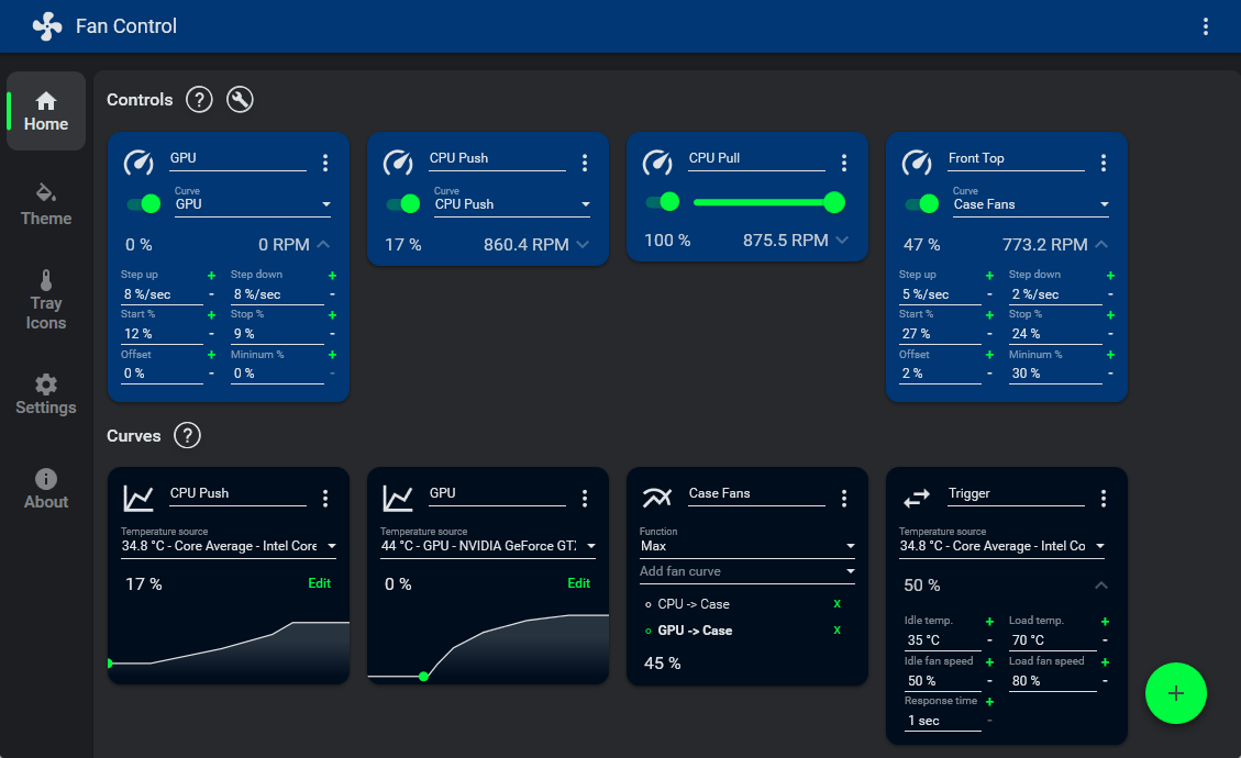 On figure 6 in more detail «increased in time» section lasting about 20 seconds, starting from 9 seconds of recording, and it shows how the increase in the output voltage is not proportional to the increase in the input signal.
Fig.5
Fig.6
Figure 7 shows the correspondence of the level at the output of the comparator OP1.1 (upper graph) to the level at the output of «CN1». The first 2.5 seconds — the control board is de-energized, then power is supplied to it and the voltage at the «OPP» point begins to gradually increase (not shown). At about 12 seconds, the OP1.1 comparator starts to work (the level of constant voltage decreases and the blurred line on it indicates the presence of ripples), the voltage at the “CN1” output at this moment grows and at 17 seconds the comparator is already fully triggered.
Fig.7
When checking the boards on a laboratory power source, it turned out that their operating modes change somewhat depending on the change in the supply voltage, i. e. «floats» the threshold.
Both control boards have a small output current — at the maximum output voltage it is limited by the parameters of the PNP structure transistors, at the minimum — by the resistances of the resistors in the voltage divider. You can judge the possible load by the fact that on the board 3BS00195, a 2SA1270 transistor (30 V; 0.5 A; 0.5 W) is installed, and on the GDP-002 94V-0 board there is 2SB1116 (50 V; 1 A; 0.75 W).
If you slightly change the circuit shown in Figure 4 (apply a higher supply voltage, increase the resistance of the resistor R9 and replace the zener diodes with a lower stabilization voltage), then you can expand the boundaries of the output voltages. This option with limits of +2.6 … + 20 V was tested, but it turned out to be bad in that at some average output voltages, transistor Q1 starts to heat up quite strongly, since increased power is released on it. Here it is required to replace it with a more powerful one (possibly with a radiator).
So, it is more or less clear with the principle of operation of control boards — one, marked 3BS00195, has a discrete mode of operation with a minimum or maximum output voltage, and the second, marked GDP-002 94V-0, has the ability for smooth adjustment , but the control voltage is in a relatively small range of possible values. However, this section can be shifted by changing the resistances of the resistors R11 and R10, the stabilization voltage of the zener diodes and the resistance R9.
It’s easy to turn the circuit into a simple «switch» that energizes or de-energizes a load. To do this, it is enough to remove the transistor Q2 and solder the right terminal of the resistor R5 to VCC (+12 V). Now the comparator OP1.1 will operate at a voltage of +6.2 V at its inverse input.
Well, now is the time to think about where they can be applied.
And, of course, the first thing that comes to mind is to use them for their intended purpose — thermal control. For example, you can turn on and off the «hood» in a greenhouse or greenhouse.
Second thought — using a photo sensor and LED strip, you can control the lighting (entrance door, corridor, just evening or night duty lighting) ( fig. 8 ).
Fig.8
Can be used as an indicator of something. If you reduce the minimum output voltage (or switch to comparator mode) and control the circuit from contact sensors, then when you connect the Ivolga sound annunciator to the output (consumption current 30 mA), you can get the simplest burglar alarm for a garage or courtyard ( fig.9 ). Or, let’s say, a signaling device for overfilling a container with liquid.
Fig.9
Of course, the latest versions of alarms can be assembled without using the control board, and using only the power supply, contacts and annunciator, but it’s more interesting!
And finally, the variant of «light-music-flashing lights» was tested. The board is switched to the “comparator” mode with a response threshold of about 0. 6 V ( fig. 10 , the red cross shows the parts that should be removed and the place where the connection is broken, the right output of R5 is connected to the positive power bus). The control signal was formed by an RC low-frequency filter and rectified with a doubling (elements marked with a stroke «`»). The signal source was a DAC with an output voltage of about 1 … 2 V. The HL1 LED is a piece of LED strip with a supply voltage of 12 V. The circuit turned out, of course, rough — without a compressor or automatic level control, but the principle is working — low-frequency signals work out well (in the application the text has a link to a video file with the work of «flashing lights» (mp4, 19MB), but without a musical sequence (Night Patrol — Loneliness 1999)).
Fig.10
In general, you can’t think of everything at once. I’ll go and please my friend…
Andrey Goltsov, Iskitim
List of radio elements
| Designation | Type | Denomination | Quantity | Note | Shop | My notepad | |
|---|---|---|---|---|---|---|---|
| Picture #4 | |||||||
| OP1 | Operational amplifier |
LM358 |
1 | Search in Otron store | To notepad | ||
| Q1 | Bipolar transistor |
2SB1116 |
1 | Search in Otron store | To notepad | ||
| Q2 | Bipolar transistor |
C945 |
1 | Search in store Otron | To notepad | ||
| ZD1, ZD2 | Zener diode |
BZX79-B6V2 |
2 | Search in store Otron | To notepad | ||
| R1, R6 | Resistor |
1 kΩ |
2 | Search in Otron store | To notepad | ||
| R5 | Resistor |
3. | |||||