How To Install a DSL Line
Install Your Own DSL Internet Connection
You can install your own DSL lines in your home
and connect them to your ISP’s network interface box.
Only a few basic tools are needed,
and the parts are available at home-improvement stores.
No doubt you already have the necessary tools stored
in your own
tool workbench.
You will need some twisted-pair Ethernet cable,
some RJ45 jacks,
and one DSL filter for each telephone.
Your voice lines and Internet connection share the
same cables.
You can put an Internet connection anywhere you can
put a phone, and vice-versa.
It’s the phone company’s property and responsibility
up to the network interface device,
and from that point on it’s all yours.
What is DSL?
DSL stands for Digital Subscriber Line.
It’s a way of combining traditional audio signals for
the voice calls with digital communication for
an Internet connection.
The telecommunications company enables DSL on your line,
and then it’s your problem to get the higher frequency
digital signals from the company’s box into the
house
and to your computers.
From the Pole to the House
The phone company has a line running down the street.
It might be an overhead line running from pole to pole,
but in newer areas it may run underground.
The drop is the line from the
telephone company’s line into the residence.
The term «drop» is getting to be old-fashioned, referring
to the days when all the telephone lines ran overhead from
pole to pole and the line into a residence literally dropped,
running from high on a pole to the exterior wall of the house
and then down into the interior wiring.
Today’s drop might be the old-style overhead line suspended
from a pole to the exterior wall of the house, as seen here.
Beware: Junk call blocking services
like NoMoRobo may not work on DSL.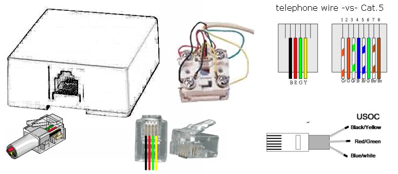
My parents recieve several Medicaid scam calls
every day because they are stuck with a
Frontier DSL landline.
Frontier apologizes but says they can do nothing,
even though most of the calls spoof Caller ID from
the same faked +1-317-999-xxxx block of numbers.
Below we see electrical power on the left.
This house is divided into three apartments, so there are
three electrical meters.
The black cables at center are for cable television.
The phone company drop is at right.
The straight black line running down the wall is the
drop from the phone company.
The large grey square box is the interface box.
From there on into the house, including the medium-sized
green box and the small grey box, and all the wiring within
the house, that’s the responsibility of the property owner.
Or, while the line down the street arches from pole to pole,
the drop might go down the pole and underground, running
through a slit cut in the lawn to the foundation, and then
either through the foundation into the basement or up
the exterior wall.
That’s what we see below, where the electrical
power line, cable, and voice/DSL lines run down the
pole, the lower sections protected by a plastic shield.
Here is a Verizon interface box on the pole at the road.
The drop comes down the pole and into this box,
where connections can be made to a buried line running
to the house.
The line below the interface box runs through a piece
of PVC tubing or thin walled pipe to protect it from damage.
The last picture above shows the interior of
the Verizon interface box on the pole.
The buried line exits the box at lower right,
we can see that it contains multiple twisted pairs.
The old voice-only drops only needed to carry baseband
audio, so a simple conductor pair was adequate.
The old one shown here is made with copper-coated
steel conductors so it can suspend itself
for an overhead drop.
But DSL needs twisted pair signaling lines to support
the much higher frequency signals.
Finally, the line down the street might be underground
and come up into a pedestal where the «drops» to nearby
households connect and run back down underground and to
the homes.
Both pictures below show pedestals.
The pedestal at in the first picture is at the base of
the utility pole, the drop comes down the pole.
The second picture shows a cluster of three pedestals
for underground lines.
From left to right they’re for Comcast/Xfinity, Verizon,
and Frontier.
Pedestals and similar boxes may contain large block
amplifiers, like this Verizon unit on H Street between
6th and 7th Streets in Chinatown in Washington D.C.
The telephone company’s line comes up out of
the ground through a plastic conduit into the NID.
The NID has been opened to attach the
blue Ethernet cable.
The drop from the phone company line runs from their
system to the Network Interface Device
or NID.
The network interface device is typically a drab
plastic box on the exterior of the house or in the
basement or otherwise in the utility entrance area.
It’s the phone company’s property and responsibility right
up to the network interface device.
From that point onward, it’s all yours.
The phone company’s line consists of a two pairs of wires.
Each pair is typically considered as part of a
loop, connecting a two-terminal device
at the customer’s end to a
two-terminal device at the phone company.
It was literally a loop years ago, now it is more likely
to behave much as though it were a loop without literally
being one.
The two wire pairs are considered, again for historical
reasons, as the ring and the
tip, referring back to when the ring and tip
of an electrical plug were connected to the two lines.
That gives us Tip 1 and Ring 1 as the two wires of pair #1,
and Tip 2 and Ring 2 as the two wires of pair #2.
The two pairs are colored, blue/white for pair #1
and orange/white for pair #2.
Practically speaking, the wires of pair #1 are
blue with a thin white stripe,
and white with a thin blue stripe.
Similarly, the wires of pair #2 are
orange with a thin white stripe,
and white with a thin orange stripe.
Connecting at the Network Interface Device
For most homes with a single line,
pair 1 is used and pair 2 is an unused spare.
You can then easily add a second line by connecting pair 2
where the drop ties into the line, and then using the
T2/R2 pair within the house.
Most residential phone wiring in the U.S. during the mid to
late 1900s used four-strand wire within the house,
with individual wires in insulation colored green, red,
black, and yellow.
This four-strand wire would support two separate lines.
But the overwhelming majority of homes had just one line.
The standard first phone line used the red/green pair,
red for ring and green for tip.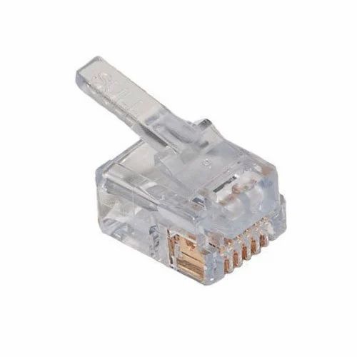
The far less commonly used second line would use yellow/black,
yellow for ring and black for tip.
| Ethernet / telco | 4-strand phone wire | |||
| T1 = white w/ blue | T1 = green | |||
| R1 = blue w/ white | R1 = red | |||
| T2 = white w/ orange | T2 = black | |||
| R2 = orange w/ white | R2 = yellow | |||
New telephone wiring projects should use quality
twisted-pair cable like that used for Ethernet.
Category 5 cable should be fine, Category 6
would be overkill if we’re just using voice plus DSL.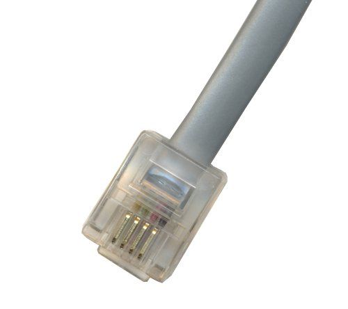
Category 5 has good performance up to 100 MHz,
5e has a tighter crosstalk specification.
When you’re connecting Ethernet cabling at the NID
or network interface device,
match its wire colors to the telephone company’s.
White-with-blue to white-with-blue and so on.
When you’re dealing with legacy wiring already in place
within the house, use the color matching shown above.
We have opened the telephone Network Interface Device to find
dirt, debris and old wasps’ nests.
The phone company’s line comes in from the
plastic conduit at bottom.
That conduit has been painted a brick-red color.
The end of the part of the cable retaining its outer
plastic jacket is wrapped in black electrical tape.
Wire pair #1 loops up to the top of the box and
back down.
This pair is blue with a thin white stripe,
and white with a thin blue stripe.
Wire pair #2, orange and white, is coiled near
the end of where the jacket has been cut away,
where the electrical tape is wrapped around
the last couple of inches of outer
jacket.
Wire pair #1 is connected to terminals at either end
of a black plastic block.
The central terminal is the ground, where you connect
the heavy green jacketed wire from the phone company
and the heavy wire, here with a beige jacket,
leading to a ground rod.
A red/green wire pair with slotted spade lugs connects
to these two terminals, leading down just a few inches
to a modular jack.
There, a 4-conductor cord just a few inches long has a
modular plug on one end, and at the other end leads to
a 4-terminal block.
This allows you to unplug that short modular jumper and
connect a phone, testing the connection out at the NID.
The screw terminals at lower left are where the lines
leading into the house connect.
Cleaning the Terminals in the
Network Interface Device
Telephone calls to this house could be frustrating
with all the noise on the line.
Hissing, crackling, popping.
There was an old FAX machine plugged into one extension
jack and a dysfunctional answering machine on another,
but I think that the corrosion in the network interface
had quite a bit to do with all the noise on the line.
We disconnected and threw out the broken old FAX and
answering machine, and then I cleaned the terminals
in the network interface.
That solved the noise problem!
The brass posts, nuts, and flat washers were
heavily corroded.
I unscrewed the nuts and removed them and the
flat washers, and then cleaned each post by
wrapping fine steel wool around it and
twisting it back and forth.
I also cleaned the faces of the nuts and the flat washers.
The posts just go into a heavy plastic block.
They aren’t really the connection itself, they allow the
connection to be made by using their threads to press
the wires, flat washers, and nuts together.
I have cleaned and started reassembling the right-side post.
The post on the left still needs lots of attention.
A Better Solution: Replace the Network Interface Device!
A much better solution is to simply replace the network
interface device!
This one was replaced by the phone company,
complete with their light blue sealant.
The left side of the box is the telco side.
The consumer’s side is on the right, where you can
connect to the terminals provided by the telco.
Filters to Separate the Voice and Data Signals
The normal voice calls use a narrow band of audio frequencies,
just up to about 4 kHz.
The DSL data signals are at higher frequencies.
We have to send the DSL data signals to the ports where
DSL modems and computers will be installed, while preventing
the DSL signals from causing interference to the telephones.
So-called DSL network connections are typically
ADSL or Asymmetric Digital Subscriber Line.
The asymmetry is the difference between the
upstream and downstream bandwidth.
Put simply, you can pull data into your home much faster
than you can push data out of it.
That’s just fine for most users, as you prefer that your
downloads and live streaming have the greater bandwidth.
Upstream traffic like sending e-mail might go a little
slower, but you’re not typically concerned because you
aren’t being inconvenienced.
| Frequencies | Use |
| 0 – 4 kHz | Voice |
| 26.075 – 138 kHz | Upstream data |
| 138 – 1104 kHz | Downstream data |
Typical ADSL systems use frequency ranges like those in
this table.
This provides close to 1 MHz of bandwidth for the downstream
(Internet to house) signaling and a little over a tenth
of that for the upstream (house to Internet) signaling.
The lower end of the data signals would cause a lot of
hissing noise if you tried to make a call while the DSL
moden is powered up.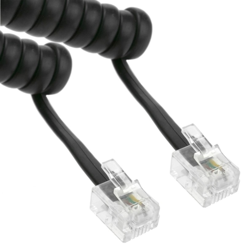
You need a DSL filter, which is just
a low-pass filter.
| L1, L2 | 6.8 mH |
| L3, L4 | 10 mH |
| C1 | 0.022 uF, 400 V |
| C2 | 0.015 uF, 400 V |
There are two ways of filtering the phone signals in a DSL
setting.
The first is to
install a DSL filter
at each telephone.
Each filter is just a little module with a very short cable;
you plug the filter into the jack and then plug the phone
into the filter.
An alternative would be to build one filter like the
one shown here.
Connect its network side to the network interface,
and connect all jacks for voice lines to its phone port.
The DSL signals will be blocked on those ports,
so you can only connect the DSL router and computer
to unfiltered jacks.
The circuit shown here is the classic one,
but the component values aren’t critical.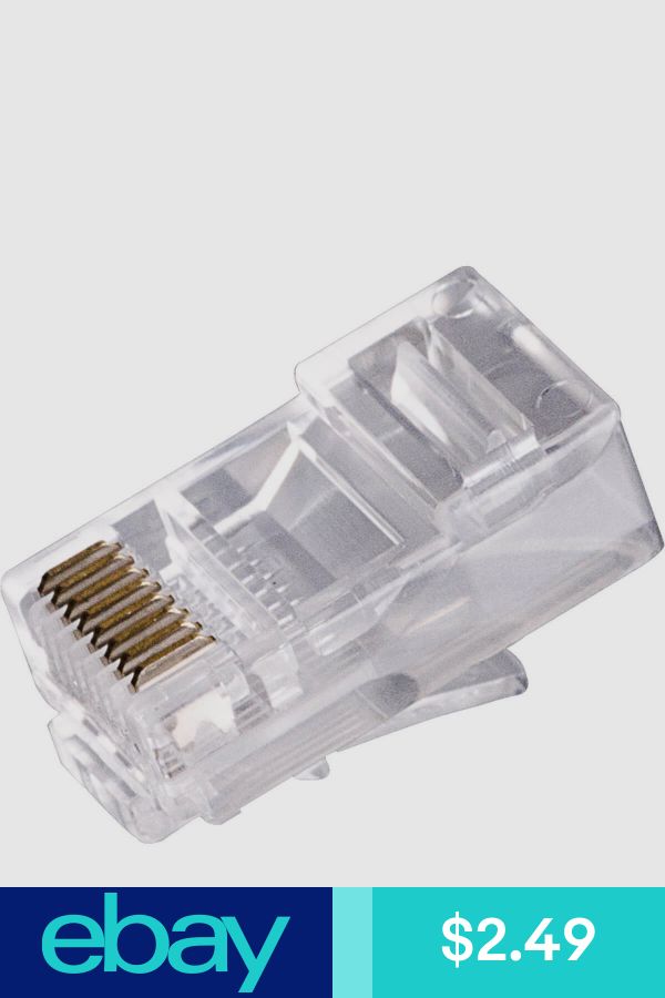
The inductance and capacitance values could be anywhere
from what’s shown here through at least 2 times these
values.
Do make sure that the capacitors are rated for at least
200 volts, as the ringer voltage is a series of pulses
nominally about 80 volts.
Wiring the Jacks
You need to run Ethernet cabling from the network interface
to at least the one jack where the DSL modem and computer
will be installed.
This might be a convenient time to re-wire other phone
jacks, and you might as well use Ethernet cabling for that.
First, strip back the outer jacket and separate the four
wire pairs.
You will find blue, orange, green and brown pairs.
Each pair is a twisted pair of wires, one that color with
a white stripe and the other white with a colored stripe.
You will just use the blue and orange pairs,
trim or fold back the green and brown pairs.
The phone jacks will probably have the old telephony colors,
so match things up appropriately:
| Ethernet / telco | 4-strand phone wire | |||
| T1 = white w/ blue | T1 = green | |||
| R1 = blue w/ white | R1 = red | |||
| T2 = white w/ orange | T2 = black | |||
| R2 = orange w/ white | R2 = yellow | |||
NAT or Network Address Translation
IP routing logic
Internet security basics
Test your jacks as you wire them in.
Remember to use a DSL filter everywhere
except where you connect the DSL router.
When you’re ready to test the Internet connection,
remember that you do not use a DSL filter there!
Use the links at right if you want to learn more about
networking and how your home now connects to the Internet.
The logic of
IP routing
relays data packets hop by hop
from your home across the Internet.
NAT or
Network Address Translation
lets you connect several computers to one DSL router,
while protecting all of them from active probes from outside.
Also check out the introduction to
Internet security.
Where not to place telco pedestals
Do not place them where this one was in
Herndon, Virginia.
It was right along a road winding through office parks,
where the anxious commuters hit speeds around 50 m.p.h.
despite that being almost twice the posted limit.
And especially not where a sidewalk ramp
makes it so easy to drift off the road while texting
and smash into the poor pedestal.
At least the pedestal slowed or stoped the car
enough to protect the tree.
Can RJ11 be used for Ethernet?
First of all: Yes you can, but it won’t make you happy. 10Mbit/s Ethernet uses 2 pairs and works quite well over short distances with the kind of cable shown, you just need to crimp an RJ45 plug on it (using the pairs 1/2 and 3/6).
Can phone plug into RJ45?
If you have a two line phone, you can plug it directly into a T568A wired jack and both lines will work. The smaller RJ11/12 plugs will fit directly inside an RJ45 jack. It’s not preferred since you might damage the other pins but it is designed to work that way.
How do I wire RJ11 to RJ45?
RJ45 and RJ11
Are RJ11 and RJ45 the same size?
RJ45 has 8 wires inside while Rj11 has 4 wires. RJ45 is bigger in size than RJ11. You cannot plug-in the RJ45 cable connector into an RJ11 jack/interface/port/slot, however, you can do the opposite.
Related Question Answers:
What is RJ11 connector used for?
(Registered Jack-11) A telephone interface that uses a cable of twisted wire pairs and a modular jack with two, four or six contacts. RJ-11 is the common connector for plugging a telephone into the wall and the handset into the telephone.
Can I use 6 wire for Ethernet?
Category 6 cable (Cat 6) is a standardized twisted pair cable for Ethernet and other network physical layers that is backward compatible with the Category 5/5e and Category 3 cable standards. Cat 6 must meet more stringent specifications for crosstalk and system noise than Cat 5 and Cat 5e.
Can you plug phone into Cat5?
Cat 5 cable and RJ-45 jacks have eight wires. Ethernet uses two pairs (four wires), one for send and one for receive. Telephones use two wires. Therefore, you can run both ethernet and telephone over the same wire, and still have two wires left over.
Can you plug a phone into a Cat6 Jack?
CONNECT CAT6 CABLE TO JACK – HOW TO
How do I wire RJ11 jack with Cat5?
Cat5e to Telephone Jack RJ 11
How do you wire a RJ11 plug?
How to make an Telephone Cable with an RJ11 Connector
How do I convert my phone jack to Ethernet?
Can You Convert Phone Jacks to Ethernet?