Rotary Paddle Bin Level Switch: KA and KAX — Silo Level Indicator
Rotary Paddle Bin Level Switch: KA and KAX — Silo Level Indicator — Monitor Technologies
Level Indication & Inventory Control for Powders & Bulk Solids
E-mail / Tel: 1-630-365-9403
(Paddle ordered separately)
Models KA / KAX Rotary
Paddle Level Switches
Similar Item(s):
SafePoint® Fail-Safe Rotary Paddle Level Sensor
Overview
Principle of Operation
The operation
of Monitor’s rotary paddle bin level switch is quite
simple. The unit is installed through the wall of the vessel,
so that the paddle protrudes inside the vessel. A small electric
motor drives a paddle which rotates freely in the absence
of material.
When the
paddle is impeded by material, the motor rotates within the
housing which triggers two switches. The first switch is
a “dry” electrical contact closure that is available
to control a process function or alarm circuit. The second
switch cuts the power to the motor, preventing a locked rotor
condition, thus extending motor life. This also activates
the signaling device which is wired through that same motor
switch. When the material level drops, the loaded stretched
tension spring returns the motor to its original running
position and the unit is reactivated.
Applications
Monitor’s
rugged, reliable design make the paddle bin level indicator (sensor de nivel) compatible with many granular, pelletized and powder bulk applications.
Monitor paddle switches can be used for high level indication
of materials over 10 lb/ft³ (160 kg/m³ ) and for
low and intermediate level indication for materials over
5 lb/ft³
(80 kg/m³). Monitor paddle units can be installed almost
anywhere dry bulk materials are stored, including bins, hoppers,
silos and tanks. Monitor’s KA unit is the most popular
of our paddle bin monitors. This model is ideal for use in
standard applications with a wide variety of materials. The
KAX incorporates all the features of the KA model, but is
specially designed to meet explosion-proof standards.
|
Typical Applications include, but |
||
Features
Available Models
Available Configurations
|
Model KA, 115 VAC, p/n 1-8301-1 |
Model KA, 12/24 VDC, p/n 1-8331-1 |
Accessories
Dimensions
are shown in inches with millimeter equivalent in brackets.
Dimensions are shown in inches with millimeter
equivalent in brackets.

Specifications
|
||||||||
|
||||||||
Warranty
Monitor
Technologies LLC warrants each rotary paddle bin indicator
it manufactures to be free from defects in material and workmanship
under normal use and service within two (2) years from the
date of purchase.
 The purchaser must give notice
of any defect to Monitor within the warranty period, return
the product intact and prepay transportation charges. The
obligation of Monitor Technologies LLC under this warranty
is limited to repair or replacement at its factory. This
warranty shall not apply to any product which is repaired
or altered outside of the Monitor Technologies LLC factory,
or which has been subject to misuse, negligence, accident,
incorrect wiring by others or improper installation. Monitor
Technologies LLC reserves the right to change the design
and/or specifications without prior notice.
Part
Numbers / Product Configurations
Part
# > Product Configuration
KA
1-8301-1 KA,115VAC,2-CT,1-1/4,UL/CSA/CE
1-8301-11 > KA,115VAC,2-CT,UL/CSA/CE,HT-CS
1-8301-12 > KA,115VAC,2-CT,UL/CSA/CE,HT-SS
1-8302-1 > KA,115VAC,3-CT,1-1/4,UL/CSA/CE
1-8302-11 > KA,115VAC,3-CT,UL/CSA/CE,HT-CS
1-8302-12 > KA,115VAC,3-CT,UL/CSA/CE,HT-SS
1-8306-1 > KA,115VAC,2-CT,1-1/2,UL/CSA/CE
1-8307-1 > KA,115VAC,3-CT,1-1/2,UL/CSA/CE
1-8311-1 > KA,230VAC,2-CT,1-1/4,UL/CSA/CE
1-8311-11 > KA,230VAC,2-CT,UL/CSA/CE,HT-CS
1-8311-12 > KA,230VAC,2-CT,UL/CSA/CE,HT-SS
1-8312-1 > KA,230VAC,3-CT,1-1/4,UL/CSA/CE
1-8312-11 > KA,230VAC,3-CT,UL/CSA/CE,HT-CS
1-8312-12 > KA,230VAC,3-CT,UL/CSA/CE,HT-SS
1-8316-1 > KA,230VAC,2-CT,1-1/2,UL/CSA/CE
1-8317-1 > KA,230VAC,3-CT,1-1/2,UL/CSA/CE
1-8331-1 > KA,12-24VDC,2-CT,1-1/4,UL/CSA/CE
1-8331-11 > KA,12-24VDC,2-CT,UL/CSA/CE,HT-CS
1-8331-12 > KA,12-24VDC,2-CT,UL/CSA/CE,HT-SS
1-8332-1 > KA,12-24VDC,3-CT,1-1/4,UL/CSA/CE
1-8332-11 > KA,12-24VDC,3-CT,UL/CSA/CE,HT-CS
1-8332-12 > KA,12-24VDC,3-CT,UL/CSA/CE,HT-SS
1-8336-1 > KA,12-24VDC,2-CT,1-1/2,UL/CSA/CE
1-8337-1 > KA,12-24VDC,3-CT,1-1/2,UL/CSA/CE
1-8381-1 > KA,24VAC,2-CT,1-1/4,UL/CSA/CE
1-8381-11 > KA,24VAC,2-CT,UL/CSA/CE,HT-CS
1-8381-12 > KA,24VAC,2-CT,UL/CSA/CE,HT-SS
1-8382-1 > KA,24VAC,3-CT,1-1/4,UL/CSA/CE
1-8382-11 > KA,24VAC,3-CT,UL/CSA/CE,HT-CS
1-8382-12 > KA,24VAC,3-CT,UL/CSA/CE,HT-SS
1-8386-1 > KA,24VAC,2-CT,1-1/2,UL/CSA/CE
1-8387-1 > KA,24VAC,3-CT,1-1/2,UL/CSA/CE
1-8391-1 > KA,48VAC,2-CT,1-1/4,UL/CSA/CE
1-8391-11 > KA,48VAC,2-CT,UL/CSA/CE,HT-CS
1-8391-12 > KA,48VAC,2-CT,UL/CSA/CE,HT-SS
1-8392-1 > KA,48VAC,3-CT,1-1/4,UL/CSA/CE
1-8392-11 > KA,48VAC,3-CT,UL/CSA/CE,HT-CS
1-8392-12 > KA,48VAC,3-CT,UL/CSA/CE,HT-SS
1-8396-1 > KA,48VAC,2-CT,1-1/2,UL/CSA/CE
1-8397-1 > KA,48VAC,3-CT,1-1/2,UL/CSA/CE
KAX
1-8401-1 > KAX,115VAC,2-CT,1-1/4,UL/CSA
1-8401-11 > KAX,115VAC,2-CT,UL/CSA,HT-CS
1-8401-12 > KAX,115VAC,2-CT,UL/CSA,HT-SS
1-8401-2 > KAX,115VAC,2-CT,1-1/4,ATEX/IECex
1-8401-21 > KAX,115VAC,2-CT,ATEX/IECEX,HT-CS
1-8401-22 > KAX,115VAC,2-CT,ATEX/IECEX,HT-SS
1-8402-1 > KAX,115VAC,3-CT,1-1/4,UL/CSA
1-8402-11 > KAX,115VAC,3-CT,UL/CSA,HT-CS
1-8402-12 > KAX,115VAC,3-CT,UL/CSA,HT-SS
1-8402-2 > KAX,115VAC,3-CT,1-1/4,ATEX/IECex
1-8402-21 > KAX,115VAC,3-CT,ATEX/IECEX,HT-CS
1-8402-22 > KAX,115VAC,3-CT,ATEX/IECEX,HT-SS
1-8406-1 > KAX,115VAC,2-CT,1-1/2,UL/CSA
1-8406-2 > KAX,115VAC,2-CT,1-1/2,ATEX/IECex
1-8407-1 > KAX,115VAC,3-CT,1-1/2,UL/CSA
1-8407-2 > KAX,115VAC,3-CT,1-1/2,ATEX/IECex
1-8411-1 > KAX,230VAC,2-CT,1-1/4,UL/CSA
1-8411-11 > KAX,230VAC,2-CT,UL/CSA,HT-CS
1-8411-12 > KAX,230VAC,2-CT,UL/CSA,HT-SS
1-8411-2 > KAX,230VAC,2-CT,1-1/4,ATEX/IECex
1-8411-21 > KAX,230VAC,2-CT,ATEX/IECEX,HT-CS
1-8411-22 > KAX,230VAC,2-CT,ATEX/IECEX,HT-SS
1-8412-1 > KAX,230VAC,3-CT,1-1/4,UL/CSA
1-8412-11 > KAX,230VAC,3-CT,UL/CSA,HT-CS
1-8412-12 > KAX,230VAC,3-CT,UL/CSA,HT-SS
1-8412-2 > KAX,230VAC,3-CT,1-1/4,ATEX/IECex
1-8412-21 > KAX,230VAC,3-CT,ATEX/IECEX,HT-CS
1-8412-22 > KAX,230VAC,3-CT,ATEX/IECEX,HT-SS
1-8416-1 > KAX,230VAC,2-CT,1-1/2,UL/CSA
1-8416-2 > KAX,230VAC,2-CT,1-1/2,ATEX/IECex
1-8417-1 > KAX,230VAC,3-CT,1-1/2,UL/CSA
1-8417-2 > KAX,230VAC,3-CT,1-1/2,ATEX/IECEX
1-8431-1 > KAX,12-24VDC,2-CT,1-1/4,UL/CSA
1-8431-11 > KAX,12-24VDC,2-CT,UL/CSA,HT-CS
1-8431-12 > KAX,12-24VDC,2-CT,UL/CSA,HT-SS
1-8431-2 > KAX,12-24VDC,2-CT,1-1/4,ATEX/IECEX
1-8431-21 > KAX,12-24VDC,2-CT,ATEX/IECEX,HT-CS
1-8431-22 > KAX,12-24VDC,2-CT,ATEX/IECEX,HT-SS
1-8432-1 > KAX,12-24VDC,3-CT,1-1/4,UL/CSA
1-8432-11 > KAX,12-24VDC,3-CT,UL/CSA,HT-CS
1-8432-12 > KAX,12-24VDC,3-CT,UL/CSA,HT-SS
1-8432-2 > KAX,12-24VDC,3-CT,1-1/4,ATEX/IECEX
1-8432-21 > KAX,12-24VDC,3-CT,ATEX/IECEX,HT-CS
1-8432-22 > KAX,12-24VDC,3-CT,ATEX/IECEX,HT-SS
1-8436-1 > KAX,12-24VDC,2-CT,1-1/2,UL/CSA
1-8436-2 > KAX,12-24VDC,2-CT,1-1/2,ATEX/IECEX
1-8437-1 > KAX,12-24VDC,3-CT,1-1/2,UL/CSA
1-8437-2 > KAX,12-24VDC,3-CT,1-1/2,ATEX/IECEX
1-8481-1 > KAX,24VAC,2-CT,1-1/4,UL/CSA
1-8481-11 > KAX,24VAC,2-CT,UL/CSA,HT-CS
1-8481-12 > KAX,24VAC,2-CT,UL/CSA,HT-SS
1-8481-2 > KAX,24VAC,2-CT,1-1/4,ATEX/IECex
1-8481-21 > KAX,24VAC,2-CT,ATEX/IECEX,HT-CS
1-8481-22 > KAX,24VAC,2-CT,ATEX/IECEX,HT-SS
1-8482-1 > KAX,24VAC,3-CT,1-1/4,UL/CSA
1-8482-11 > KAX,24VAC,3-CT,UL/CSA,HT-CS
1-8482-12 > KAX,24VAC,3-CT,UL/CSA,HT-SS
1-8482-2 > KAX,24VAC,3-CT,1-1/4,ATEX/IECex
1-8482-21 > KAX,24VAC,3-CT,ATEX/IECEX,HT-CS
1-8482-22 > KAX,24VAC,3-CT,ATEX/IECEX,HT-SS
1-8486-1 > KAX,24VAC,2-CT,1-1/2,UL/CSA
1-8486-2 > KAX,24VAC,2-CT,1-1/2,ATEX/IECex
1-8487-1 > KAX,24VAC,3-CT,1-1/2,UL/CSA
1-8487-2 > KAX,24VAC,3-CT,1-1/2,ATEX/IECex
1-8491-1 > KAX,48VAC,2-CT,1-1/4,UL/CSA
1-8491-11 > KAX,48VAC,2-CT,UL/CSA,HT-CS
1-8491-12 > KAX,48VAC,2-CT,UL/CSA,HT-SS
1-8491-2 > KAX,48VAC,2-CT,1-1/4,ATEX/IECex
1-8491-21 > KAX,48VAC,2-CT,ATEX/IECEX,HT-CS
1-8491-22 > KAX,48VAC,2-CT,ATEX/IECEX,HT-SS
1-8492-1 > KAX,48VAC,3-CT,1-1/4,UL/CSA
1-8492-11 > KAX,48VAC,3-CT,UL/CSA,HT-CS
1-8492-12 > KAX,48VAC,3-CT,UL/CSA,HT-SS
1-8492-2 > KAX,48VAC,3-CT,1-1/4,ATEX/IECex
1-8492-21 > KAX,48VAC,3-CT,ATEX/IECEX,HT-CS
1-8492-22 > KAX,48VAC,3-CT,ATEX/IECEX,HT-SS
1-8496-1 > KAX,48VAC,2-CT,1-1/2,UL/CSA
1-8496-2 > KAX,48VAC,2-CT,1-1/2,ATEX/IECex
1-8497-1 > KAX,48VAC,3-CT,1-1/2,UL/CSA
1-8497-2 > KAX,48VAC,3-CT,1-1/2,ATEX/IECex
Last Rev.
 : May 21, 2021
Bin Level Switches, Indicators, Sensors, Controls, Detectors, Probes
Level Indication & Inventory Control for Powders & Bulk Solids
E-mail / Tel: 1-630-365-9403
Level Indication and Level Controls Using a Variety of Technologies:
Monitor Technologies is a leading provider for a wide range of solutions in point level indication, level detection and level control for the storage of powders & bulk solids in bins, silos, vessels, etc.
Level Sensor Types Including: Rotary Paddle, Fail-Safe Rotary Paddle, RF Capacitance, Vibratory, Tilt
Switch, Proximity and Pressure Sensitive.
For over 60 years Monitor Technologies, LLC has strived to offer high quality products, extensive application support and trusted customer support.
Markets Served:
Monitor offers level indication & detection solutions for a large selection of industries / target materials including (but not limited to): plastics, cement and aggregates, fly ash, mining, coal / power plants, feed and grain, biofuels, food ingredients, baking & snacks, pet food, pulp & paper, food packaging, pharmaceuticals, chemicals and more powders and bulk solids. Also some slurry and liquid applications.
Need some more information?…Click on the button.
Rotary Paddle Level Switches — Models KA and KAX
Economical point level control sensors for the detection
of dry bulk materials. This level switch is ideal for use
as low level and high level indicators in bins, silos,
hoppers, and other vessels. (Sensor de Nivel)
Details
on KA / KAX Rotary Paddle Bin Level Monitors >>
Rotary Paddle — SafePoint® Truly Fail-Safe Sensor
The SafePoint® rotary paddle bin level monitor / indicator / detector
provides the ultimate in fail-safe performance wherever critical
continuous operation
must be
ensured. Detection
of both material presence/absence and its own operational
status is
performed on a continuous basis.
Details on SafePoint® Fail-Safe
Rotary Paddle Level Indicator >>
Diaphragm Switches
The flush mount, minimally-intrusive BINATROL® (Model G/GX/GX-SS) diaphragm level switch is ideally used when vessel size or internal clearance is limited, or where protrusion into a vessel is not acceptable.
Details on Diaphragm Switches >>
RF Capacitance – MK2
TrueCap® RF capacitance probes are designed to provide a high level of sensitivity, stability and durability for powder and bulk solids applications, as well as liquid and slurry applications. The Model MK2 is a state-of-the-art point level sensor providing maximum performance, reliability and value.
Details on RF Capacitance – MK2 >>
RF Capacitance – MK2e
TrueCap® RF capacitance probes are designed to provide a high level of sensitivity, stability and durability for powder and bulk solids applications, as well as liquid and slurry applications. The model MK2e provides high quality and performance at the lowest possible price.
Details on RF Capacitance – MK2e >>
Proximity Switch
Solid state compact capacitance-type point level switches used to detect the absence or presence of bulk solids.
Details
on Proximity Switch >>
Vibratory Probe –
DuraVibeTM Model PZP
The vibrating level probe principle for the Model PZP eliminates level
indicator problems associated with temperature, humidity and
material changes, while providing state-of-the-art electronic
reliability and accuracy that requires no calibration. Extremely sensitive and works on a wide range of material densities…from very light to heavy.
Diamond-shape single probe design for less material build-up on probe and is tip sensitive to be unaffected by material build-up near mounting base.
Details
on Vibratory Probe
– PZP >>
Vibratory Probe –
DuraVibeTM
Model VibraRodTM
The vibrating probe principle eliminates problems associated with temperature, humidity and material changes, while providing state-of-the-art electronic reliability and accuracy that requires no calibration. The Model VibraRod™ provides reliable point level measurement sensing in a wide variety of applications within powder and bulk solids markets.
Single probe design prevents false signals that may happen with «tuning fork» style probes that can have material packed between the forks.
Details on Vibratory Probe
– VibraRod™ >>
Tilt Switches – TC-1 and TC-3
The Model TC-1 and TC-3 tilt switches can be used as high level indicators to eliminate bin overflow or to control levels in open piles.
Details on Tilt Switches
— TC-1 and TC-3 >>
Continuous Level Measurement Sensors for Powders and Bulk Solids in Bins, Silos, Tanks, Vessels
Level Indication & Inventory Control for Powders & Bulk Solids
E-mail / Tel: 1-630-365-9403
Products & Solutions Using a Variety of Level Technologies:
Monitor Technologies is a leading provider for a wide range of solutions in continuous level measurement and remote inventory management systems for the storage of powders & bulk solids in bins, silos, vessels, etc.
Level Sensor and Transmitter Types Including: Silo Patrol® cable-based level measurement and RadarRight[TM] non-contact radar level sensor. Sensors can interface with a Web-based inventory management software to view data anytime.
For over 60 years Monitor Technologies, LLC has strived to offer high quality products, extensive application support and trusted customer support.
Markets Served:
Monitor offers application solutions for a large selection of industries / target materials including (but not limited to): cement and aggregates, fly ash, mining, coal / power plants, plastics, biofuels, feed and grain, ingredients, baking & snacks, pet food, food packaging, pulp & paper, pharmaceuticals, chemicals and more powders and bulk solids. Also some slurry and liquid applications.
Need some more information?…Click on the button.
|
SiloTrack Cloud |
| CONTINUOUS LEVEL QUICK REFERENCE CHART | |
| Plumb Bob Style | Non-Contact Radar |
| > Measuring range up to 150 ft (45.  7 m) in height. 7 m) in height.> Measurements taken at continuous intervals or on-demand. > Not affected by material composition, including dielectric. > Electromechanical design. |
> Measuring range up to 100 ft (30 m) in height for solids and liquids > Continuous, instantaneous (real-time) measurements. > Non-Contact …nothing to «touch» your process > Material’s dielectric needs to be considered. > Electronic…No moving parts. |
SiloPatrol®
Weight & Cable-Based Level Measurement
The SiloPatrol® SE continuous level measurement and inventory monitoring system is a truly robust smart cable-based (weight and cable / plumb bob / yo yo type) bin level sensor system. It is a field-proven approach to reliably monitoring the level of material in bins, silos and tanks.
Details on SiloPatrol
SE >>
RadarRight™
Non-Contact Radar Continuous Level Sensors
RadarRight™ is a non-contact continuous level measurement sensor which means there is nothing to «touch» your process. Provides dependable,
real-time level measurements at the «right» price for the storage of powders, bulk solids and liquids.
Details on Series 400 for Bulk Solids>>
Details on Series 200 for Liquids>>
Need some more information?…Click on the button.
SiloTrack™ Cloud Inventory Management Web Application
SiloTrack™ Cloud Remote Inventory Management Software is a web-based application software that provides users with an unsurpassed, flexible graphical interface for our SiloPatrol® SE Model SMU inventory monitoring sensors and our RadarRight(TM) non-contact radar continuous level measurement sensors.
Details on SiloTrack Cloud >>
SiloTrack™PC Inventory Management Software
SiloTrack™ PC Inventory Management Software is a PC-based application software that provides users with an unsurpassed, flexible graphical interface for our SiloPatrol® SE Model SMU inventory monitoring sensors and our Flexar® guided wave radar continuous level measurement sensors.
Details on SiloTrack PC >>
HMI2 Local Operator Interface
The multi-functional HMI2 controls level sensor operations, displays measured and calculated data and performs/displays system and sensor diagnostic messages via two separate RS-485 communication networks. The HMI2 operator interface control console provides convenient, local interface for Monitor’s “Smart” RS-485 SiloPatrol® SMU SE cable-based inventory monitoring sensors, RadarRight(TM) non-contact radar level sensors and/or Flexar® guided wave radar level sensors. HMI2 allows for monitoring up to 32 SMU SE, RadarRight and/or Flexar sensors.
Details on HMI2 >>
WirelessEZ Communication Interface
The WirelessEZ Communication Interface (radio modem) is compatible with the the SiloPatrol® SE (SMU) «smart» cable-based sensor or Flexar guided wave radar level sensor.
Details on WirelessEZ >>
Liquid Crystal Display (LCD) Technology / Monitors & Projectors
Original: HWExtreme
Translation: Dmitry Chekanov, Sergey Milchakov
Introduction
The first working liquid crystal display was created by Fergason in 1970. Prior to this, liquid crystal devices consumed too much power, their life was limited, and the image contrast was deplorable. The new LCD was presented to the public at 1971 years and then he received warm approval. Liquid crystals (Liquid Crystal) are organic substances that can change the amount of transmitted light under voltage. The liquid crystal monitor consists of two glass or plastic plates, between which there is a suspension. The crystals in this suspension are arranged parallel to each other, thereby allowing light to pass through the panel. When an electric current is applied, the arrangement of the crystals changes, and they begin to interfere with the passage of light. LCD technology has become widespread in computers and projection equipment.
Note that the first liquid crystals were notable for their instability and were of little use for mass production. The real development of LCD technology began with the invention by English scientists of a stable liquid crystal — biphenyl (Biphenyl). First generation liquid crystal displays can be seen in calculators, electronic games and watches.
Let’s enjoy the flat screen
Modern LCD monitors are also called flat panels, dual scan active matrix, thin film transistors. The idea of LCD monitors has been in the air for more than 30 years, but the research has not led to an acceptable result, so LCD monitors have not gained a reputation for good image quality. Now they are becoming popular — everyone likes their elegant appearance, thin body, compactness, economy (15-30 watts), in addition, it is believed that only wealthy and serious people can afford such a luxury.
As time goes by, prices are falling, and LCD monitors are getting better and better. Now they provide a high-quality contrast, bright, distinct image. It is for this reason that users are switching from traditional CRT monitors to LCDs. In the past, LCD technologies were slower, they were not as efficient, and their contrast levels were low. The first matrix technologies, the so-called passive matrices, worked quite well with textual information, but with a sharp change in the picture, so-called «ghosts» remained on the screen. Therefore, this kind of device was not suitable for watching videos and playing games. Today, most black-and-white portable computers, pagers and mobile phones operate on passive matrices. Because LCD technology addresses each pixel individually, the resulting text is crisper than a CRT monitor. Note that on CRT monitors, with poor beam convergence, the pixels that make up the image are blurred.
There are two types of LCD monitors: DSTN (dual-scan twisted nematic — crystal screens with double scanning) and TFT (thin film transistor — on thin film transistors), also they are called respectively passive and active matrices. Such monitors consist of the following layers: a polarizing filter, a glass layer, an electrode, a control layer, liquid crystals, another control layer, an electrode, a glass layer, and a polarizing filter.
Early computers used eight-inch (diagonal) passive black and white matrices. With the transition to active matrix technology, the screen size has grown. Virtually all modern LCD monitors use thin-film-transistor panels, which provide a bright, clear image of a much larger size.
How the LCD Monitor Works
The cross section of the TFT panel is a sandwich sandwich. The outer layer of either side is made of glass. Between these layers is a thin film transistor, a color filter panel that provides the desired color — red, blue or green, and a layer of liquid crystals. On top of that, there is a fluorescent backlight that illuminates the screen from the inside.
Under normal conditions, when there is no electric charge, liquid crystals are in an amorphous state. In this state, liquid crystals transmit light. The amount of light passing through liquid crystals can be controlled by electrical charges — this changes the orientation of the crystals.
As in traditional CRTs, a pixel is formed from three areas — red, green and blue. And different colors are obtained as a result of a change in the magnitude of the corresponding electric charge (which leads to the rotation of the crystal and a change in the brightness of the passing light flux).
TFT screen consists of a whole grid of such pixels, where each color area of each pixel is controlled by a separate transistor. This is where it is worth talking about resolution.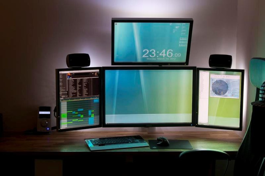 To properly provide a screen resolution of 1024×768 (SVGA mode), the monitor must have exactly this number of pixels.
Why LCD?
LCD monitors have a completely different style. In traditional cathode-beam monitors, the kinescope was the shaping factor. Its size and shape could not be changed. There is no kinescope in LCD monitors, so monitors of any shape can be produced.
Compare a 15-inch CRT monitor weighing 15 kg with an LCD panel less than 15 cm deep (including stand) and weighing 5-6 kg. The advantages of such monitors are clear. They’re not as bulky, don’t have trouble focusing, and their clarity makes it easy to work at high screen resolutions, even if the screen size isn’t that big. For example, even a 17-inch LCD monitor perfectly displays at a resolution of 1280×1024, while even for 18-inch CRT monitors this is the limit. Also, unlike CRT monitors, most LCDs are digital. This means that a digital-out graphics card does not have to do the digital-to-analog conversion that it does with a CRT monitor.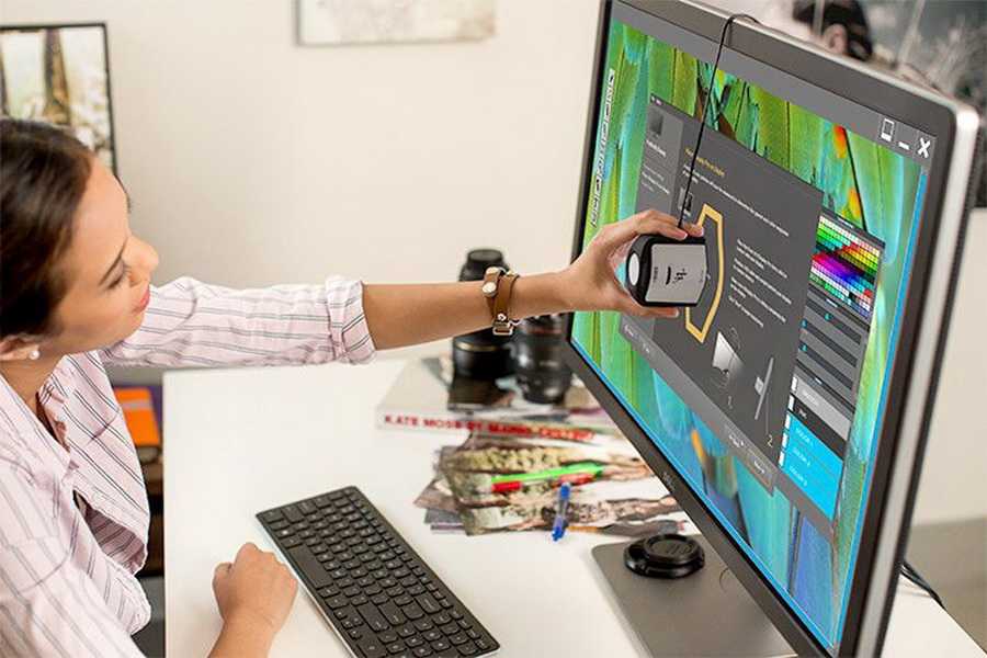 Theoretically, this allows more accurate transmission of color and pixel location information. At the same time, if you connect an LCD monitor to a standard analog VGA output, you will have to carry out analog-to-digital conversions (after all, LCD panels are digital devices). In this case, various unwanted artifacts may occur. Now that standards have been adopted and more and more cards are provided with digital outputs, the situation will be much simpler.
Benefits of LCD monitors
- LCD monitors are more economical;
- They have no electromagnetic radiation compared to CRT monitors;
- They do not flicker like CRT monitors;
- They are light and not bulky;
- They have a large visible screen area.
Other differences include:
Resolution: CRT monitors can run at multiple resolutions in full screen mode, while the LCD monitor can only run at one resolution.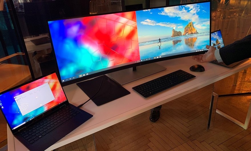 Smaller resolutions are possible only when using part of the screen. So, for example, on a monitor with a resolution of 1024×768, when working at a resolution of 640×480, only 66% of the screen will be used.
Diagonal measurement: The size of the diagonal of the visible area of the LCD monitor corresponds to the size of its real diagonal. In CRT monitors, the real diagonal loses more than an inch outside the monitor frame.
Beam convergence: In LCD monitors, each pixel is turned on or off separately, so there is no problem with beam convergence, unlike CRT monitors, where the electron guns must work flawlessly.
Signals: CRT monitors use analog signals while LCD monitors use digital signals.
Flicker-free: LCD monitors have better image quality and less strain on the eyes during operation due to the smooth screen plane and the absence of flicker.
How to choose an LCD monitor?
«Looks can be deceiving» — this statement applies to everything, including LCD monitors.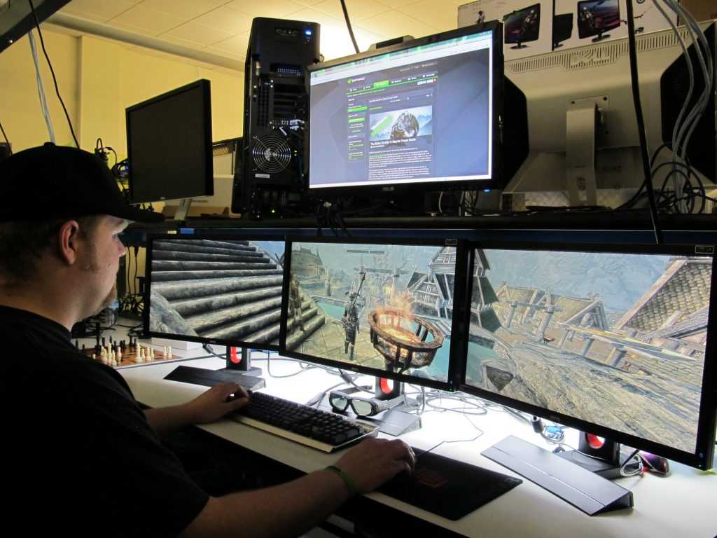 Most inexperienced buyers make their choice based on the appearance of the monitor. When buying a monitor, first of all, you should consider the following.
«Dead pixels» — a few pixels may not work on a flat panel. It is not difficult to recognize them — they are always the same color. They arise during the production process and cannot be restored. It is considered acceptable when the monitor has no more than three such pixels. In some cases, these pixels can be annoying — especially when watching movies. Therefore, if the absence of dead pixels is critical for you, check it before buying a specific monitor.
Viewing Angle — If you have ever used a laptop before, you probably know that the best viewing angle for an LCD monitor is a certain one. With some monitors, this angle is quite large, so you can see the image on the monitor even when the monitor is not directly in front of you. Note that some laptop owners find small angle values useful in cases where you want your neighbor not to see what is happening on the screen of your monitor. So, an angle of 120 degrees is considered quite good.
Contrast — Pixels themselves do not produce light, they only transmit light from the backlight. And a dark screen doesn’t mean the backlight isn’t working — it’s just that the pixels block that light and don’t let it through the screen. The contrast of an LCD monitor refers to how many levels of brightness its pixels can produce. Generally, a contrast ratio of 250:1 is considered good.
Brightness — how bright can an LCD monitor be? In truth, the brightness of a liquid crystal display can be higher than that of a cathode ray tube. But, as a rule, the brightness of an LCD monitor does not exceed 225 candelas per square meter — this is comparable to the brightness of a TV.
Screen Size — Like CRT monitors, LCD monitors are sized by the diagonal. Note, however, that LCD monitors do not have the black frame that CRT monitors have. So a 15.1-inch screen actually shows 15.1 inches (usually this corresponds to a resolution of 1024×768). A 17.1-inch LCD monitor will work at a resolution of 1280×1024.
How to choose an LCD monitor?
There are many different manufacturers of LCD monitors. The best known monitors are Viewsonic, Sony, Silicon Graphics, Samsung, Nec, Eizo Nano and Apple. Usually cool guys sit behind such monitors. Please note that no modern film is complete without LCD monitors — they are so attractive. Recall, for example, recent action films: Lara Croft from Tomb Raider was surrounded by Sony N50s, and Swordfish used Silicon Graphics 1600SW in the computer room. Don’t they look attractive?
looks good, light, very thin (only 1.2 cm) — 15″
Only 1.2 cm thick, beautiful, expensive, high-quality picture, and in general, a feast for the eyes — 18″
Viewsonic VP181 — expensive, has inputs and outputs for TV, VCD, DBD, in addition, built-in speakers — 18″;
Apple Cinema Display — high resolution, large screen, different design — 22″;
Sony M81 — thin, but actually look a little different than in this picture — 18″
SGI 1600SW — distinguished by design, excellent performance, expensive — 17″;
Sony L181 — very thin, very expensive, but using Trinitron technology — 18″;
Eizo Nano — look elegant, expensive — 18″
Additional materials:
LCD, PDP, LEP monitors
LCD monitors, 2002 version
LCD monitor.
 LCD technology, working principle. TFT matrix device | Eco
September 08, 2019
LCD matrix. The principle of operation of the liquid crystal panel.
The «heart» of any liquid crystal monitor is the LCD matrix (Liquid Cristal Display). The LCD panel is a complex multilayer structure. A simplified diagram of a color TFT LCD panel is shown in Fig.2.
The principle of operation of any liquid crystal screen is based on the property of liquid crystals to change (rotate) the plane of polarization of the light passing through them in proportion to the voltage applied to them. If a polarizing light filter (polarizer) is placed in the path of polarized light that has passed through liquid crystals, then by changing the magnitude of the voltage applied to the liquid crystals, it is possible to control the amount of light transmitted by the polarizing light filter. If the angle between the polarization planes of the light transmitted through the liquid crystals and the light filter is 0 degrees, then the light will pass through the polarizer without loss (maximum transparency), if 90 degrees, then the filter will let in the minimum amount of light (minimum transparency).
| How the LCD panel works |
Fig.1. LCD monitor. How LCD technology works.
Thus, using liquid crystals, it is possible to manufacture optical elements with a variable degree of transparency. The level of light transmission of such an element depends on the voltage applied to it. Any LCD screen on a computer monitor, laptop, tablet or TV contains from several hundred thousand to several million such cells, the size of fractions of a millimeter. They are combined into an LCD matrix and with their help we can form an image on the surface of the liquid crystal screen.
Liquid crystals were discovered at the end of the 19th century. However, the first display devices based on them appeared only in the late 60s of the XX century. The first attempts to use LCD screens in computers were made in the 1980s. The first liquid crystal monitors were monochrome and far inferior in image quality to cathode ray tube (CRT) displays. The main disadvantages of LCD-monitors of the first generations were:
- — low speed and image inertia;
- — «tails» and «shadows» in the image from the elements of the picture;
- — poor image resolution;
- — black and white or color image with low color depth;
- — etc.
However, progress did not stand still and, over time, new materials and technologies were developed in the manufacture of liquid crystal monitors. Advances in microelectronics technology and the development of new substances with the properties of liquid crystals have significantly improved the characteristics of LCD monitors.
Design and operation of TFT LCD matrix.
One of the major achievements was the invention of LCD TFT-matrix technology — a liquid crystal matrix with thin film transistors (Thin Film Transistors). TFT monitors have dramatically increased the speed of pixels, increased the color depth of the image and managed to get rid of «tails» and «shadows».
The structure of the TFT panel is shown in Fig.2
| LCD panel structure |
Fig.2. Diagram of the structure of a TFT LCD matrix.
A full-color image on an LCD matrix is formed from individual dots (pixels), each of which usually consists of three elements (subpixels) responsible for the brightness of each of the main color components — usually red (R), green (G) and blue ( B) — RGB. The monitor’s video system continuously scans all subpixels of the matrix, writing to the storage capacitors a charge level proportional to the brightness of each subpixel. Thin-film transistors (Thin FilmTrasistor (TFT) — in fact, that’s why the TFT-matrix is called) connect storage capacitors to the bus with data at the time information is written to this subpixel and switch the storage capacitor to charge-saving mode for the rest of the time.
The voltage stored in the storage capacitor of the TFT array acts on the liquid crystals of the given sub-pixel, turning the plane of polarization of the light from the backlight passing through them by an angle proportional to this voltage. After passing through a cell with liquid crystals, the light enters a matrix light filter, on which a light filter of one of the primary colors (RGB) is formed for each subpixel. The pattern of relative positions of dots of different colors for each type of LCD panel is different, but this is a separate issue. Further, the formed luminous flux of the primary colors enters the external polarization filter, the light transmittance of which depends on the polarization angle of the light wave incident on it. A polarizing filter is transparent to those light waves whose plane of polarization is parallel to its own plane of polarization. As this angle increases, the polarizing filter begins to transmit less and less light, up to maximum attenuation at an angle of 90 degrees. Ideally, a polarizing filter should not let light polarized orthogonally to its own plane of polarization pass through, but in real life, a small fraction of the light does get through. As a result, all LCDs suffer from a lack of black depth, which is especially pronounced at high backlight brightness levels.
As a result, in an LCD display, the light flux from some subpixels passes through a polarizing filter without loss, from other subpixels it is attenuated by a certain amount, and from some part of the subpixels it is almost completely absorbed. Thus, by adjusting the level of each primary color in individual subpixels, a pixel of any color shade can be obtained from them. And from a set of color pixels to make a full-screen color image.
LCD monitor allowed to make a major breakthrough in computer technology, making it available to a large number of people. Moreover, without an LCD screen, it would be impossible to create portable computers such as laptops and netbooks, tablets and cell phones. But is everything so cloudless with the use of liquid crystal displays?
Did you like the material? Share it on social networks:
tn, ips, pls, va, mva, oled
Contents
- Types of monitor matrices, their characteristics, similarities and differences
- TN Matrix
- TN+FILM Matrix
- TFT Matrix
- IPS or SFT Matrix
- Types IPS Matrix:
- PLS Matrix
- VA, MVA and PVA Matrix
- Which matrix is better, how do they affect vision?
- Conclusions
9999 monitor?
At present, two of the most basic, so to speak, root, matrix manufacturing technologies, LCD and LED, are used for the production of consumer monitors.
- LCD is an abbreviation for the phrase «Liquid Crystal Display», which, translated into understandable Russian, means a liquid crystal display, or LCD.
- LED stands for «Light Emitting Diode», which in our language is read as a light emitting diode, or simply an LED.
All other types are derivatives of these two pillars of display construction and are modified, modernized and improved versions of their predecessors.
Well, let’s now consider the evolutionary process that displays went through when becoming at the service of humanity.
Types of monitor matrices, their characteristics, similarities and differences
Let’s start with the most familiar to us LCD screen. It consists of:
- The matrix, which at first was a sandwich of glass plates interspersed with a film of liquid crystals. Later, with the development of technology, thin sheets of plastic began to be used instead of glass.
- Light source.
- Connecting wires.
- Housing with a metal frame that stiffens the product
The point of the screen responsible for forming the image is called pixel and consists of:
- Two transparent electrodes.
- Interlayers of active substance molecules between electrodes (this is LC).
- Polarizers whose optical axes are perpendicular to each other (depending on design).
If there were no LC between the filters, then the light from the source passing through the first filter and being polarized in one direction would be completely delayed by the second, due to its optical axis being perpendicular to the axis of the first filter. Therefore, no matter how we shine on one side of the matrix, it remains black on the other side.
The surface of the electrodes touching the LC is processed in such a way as to create a certain order of arrangement of molecules in space. In other words, their orientation, which tends to change depending on the magnitude of the voltage of the electric current applied to the electrodes. Further, technological differences begin depending on the type of matrix.
TN matrix
Tn matrix stands for «Twisted Nematic», which means «Wriggling Threadlike» in translation. The initial arrangement of the molecule is in the form of a quarter-turn spiral. That is, the light from the first filter is refracted so that, passing along the crystal, it enters the second filter in accordance with its optical axis. Therefore, in a quiet state, such a cell is always transparent.
By applying voltage to the electrodes, it is possible to change the angle of rotation of the crystal up to its complete straightening, at which light passes through the crystal without refraction. And since it was already polarized by the first filter, the second one will completely delay it, and the cell will be black. Changing the voltage value changes the angle of rotation, and, accordingly, the degree of transparency.
Advantages of — low response time, low cost.
Disadvantages of — small viewing angles, low contrast, poor color reproduction, inertia, power consumption
TN + Film matrix
It differs from simple TN by the presence of a special layer designed to increase the viewing resolution in degrees. In practice, a value of 150 degrees horizontal is achieved for the best models. It is used in the vast majority of budget-level TVs and monitors.
Advantages of — low response time, low cost.
Disadvantages of — viewing angles are very small, low contrast, poor color reproduction, inertia.
TFT Matrix
Short for «Think Film Transistor» and translates to «Thin Film Transistor». The name TN-TFT would be more correct, since this is not a type of matrix, but a manufacturing technology and the difference from pure TN is only in the way pixels are controlled. Here it is implemented using microscopic field-effect transistors, and therefore such screens belong to the class of active LCDs. That is, this is not a type of matrix, but a way to control it.
IPS or SFT matrix
Yes, and this is also a descendant of the most ancient LCD plate. In fact, it is a more developed and modernized TFT, as Super Fine TFT is called (very good TFT). The viewing angle of the best products is increased to 178 degrees, and the color gamut is almost identical to the natural
.
Advantages of — viewing angles, color reproduction.
Disadvantages of — the price is too high compared to TN, the response time is rarely below 16 ms.
Types of IPS matrix:
- H-IPS — increases image contrast and reduces response time.
- AS-IPS — the main quality is to increase the contrast.
- H-IPS A-TW — H-IPS with «True White» technology that enhances whites and whites.
- AFFS — increased electric field strength for large viewing angles and brightness.
PLS matrix
Modified IPS version to reduce costs and optimize response time (up to 5 milliseconds). Launched by the Samsung concern and is an analogue of H-IPS, AN-IPS, which are patented by other electronics developers.
More information about the PLS matrix can be found in our article:
PLS matrix type — manufacturing technology, features, pros and cons. IPS vs PLS
VA, MVA and PVA matrices
This is also a manufacturing technology, not a separate type of screen.
- VA Matrix is short for «Vertical Alignment». Unlike TN matrices, VA matrices do not transmit light in the off state
- MVA matrices . Modified VA. The goal of the optimization was to increase viewing angles. Reducing the response time was possible thanks to the use of OverDrive technology.
- PVA matrix . It is not a separate species. It is an MVA patented by Samsung under its own name.
There is also an even greater number of various improvements and improvements that the average user is unlikely to encounter in practice — the maximum that the manufacturer indicates on the box is the main type of screen and that’s it.
In parallel with LCDs, LED technology has evolved. Full-fledged, purebred LED screens are made from discrete LEDs either in a matrix or cluster way and are not found in household appliance stores.
The reason for the absence of full-weight LEDs on sale lies in their large dimensions, low resolution, and coarse grain. The destiny of such devices is banners, outdoor TV, media facades, a ticker device.
Attention! Don’t confuse the marketing name like «LED monitor» with a real LED display. Most often, this name will hide a conventional LCD of the TN + Film type, but the backlight will be made using an LED lamp, not a fluorescent one. This is all that in such a monitor will be from LED technology — only the backlight.
OLED displays
A separate segment is OLED displays, which are one of the most promising areas:
Advantages
- low weight and overall dimensions;
- low appetite for electricity;
- unlimited geometric shapes;
- no special lamp required;
- viewing angles up to 180 degrees;
- instantaneous matrix response;
- contrast exceeds all known alternative technologies;
- the ability to create flexible screens;
- temperature range is wider than other screens.
Disadvantages
- short service life of certain color diodes;
- the inability to create durable full-color displays;
- is a very high price, even compared to IPS.
For reference. Perhaps we are also read by lovers of mobile devices, so we will also touch on the sector of portable equipment:
AMOLED (Active Matrix Organic Light-Emitting Diode) — a combination of LED and TFT
Super AMOLED — Well, we think everything is clear here!
Based on the data provided, it follows that there are two types of monitor matrices — liquid crystal and LED. Combinations and variations are also possible.
You should know that the matrices are divided by ISO 13406-2 and GOST R 52324-2005 into four classes, which we will only say that the first class provides for the complete absence of dead pixels, and the fourth class allows up to 262 defects per million points.
How do I know which matrix is in the monitor?
There are 3 ways to verify the type of matrix of your screen:
a) If the packing box and technical documentation have been preserved, then you can probably see a table with the characteristics of the device, among which the information of interest will be indicated.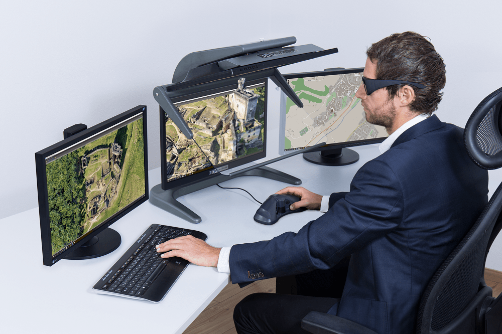
b) Knowing the model and name, you can use the services of the manufacturer’s online resource.
c) Use our recommendations:
- If you look at a color picture of a TN monitor from different angles from the side-top-bottom, you will see color distortions (up to inversion), fading, yellowness of the white background. It is impossible to achieve completely black color — it will be deep gray, but not black.
- IPS is easy to identify by the black picture, which turns purple when the eye deviates from the perpendicular axis.
- If the listed manifestations are absent, then this is either a more modern version of IPS or OLED.
- OLED is distinguished from all others by the absence of a backlight, so the black color on such a matrix is a completely de-energized pixel. And even the best IPS has a black color that glows in the dark due to BackLight.
Let’s find out which is the best matrix for a monitor.
Which matrix is better, how do they affect vision?
So, the choice in stores is limited to three technologies TN, IPS, OLED.
TN matrix 9The 0150 is low cost, has acceptable time delays, and is constantly improving image quality. But due to the low quality of the final image, it can only be recommended for home use — sometimes to watch a movie, sometimes to drive a toy and from time to time work with texas. As you remember, the response time for the best models reaches 4 ms. Disadvantages in the form of poor contrast and unnatural color causes increased eye fatigue.
IPS is, of course, a completely different matter! Bright, juicy and natural colors of the transferred picture will provide excellent comfort of work. Recommended for printing works, designers or those who are willing to pay a tidy sum for convenience. Well, it will not be very convenient to play due to the high response — not all instances can boast even 16 ms. Accordingly — calm, thoughtful work — YES. It’s cool to watch a movie — YES! Dynamic shooting games — NO! But the eyes do not get tired.
OLED .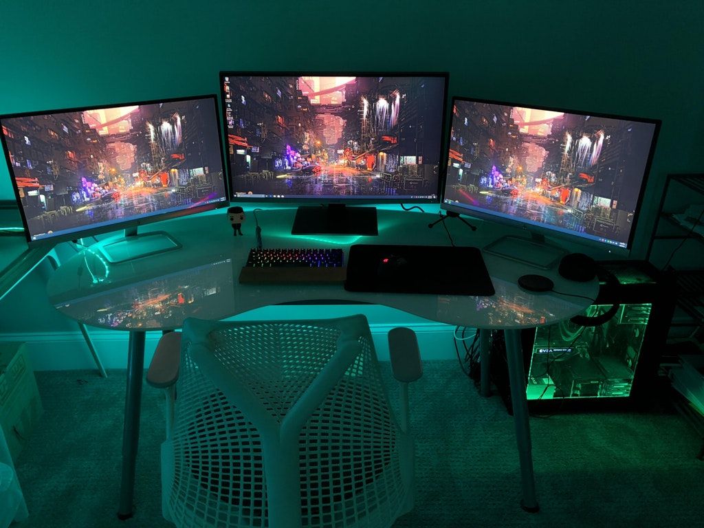 Ah, the dream! Such a monitor can be afforded either by fairly wealthy people, or those who care about the state of their vision. If not for the price, we could recommend it to everyone and everyone — the characteristics of these displays have the advantages of all other technological solutions. In our opinion, there are no drawbacks here, except for the cost. But there is hope — the technology is improving and, accordingly, cheaper so that a natural decrease in production costs for manufacturing is expected, which will make them more affordable.
Conclusions
To date, the best matrix for a monitor is, of course, Ips / Oled, made according to the principle of organic light emitting diodes, and they are quite actively used in the field of portable equipment — mobile phones, tablets and others.