Prime95 With AVX Or SSE
Skip to main content
When you purchase through links on our site, we may earn an affiliate commission. Here’s how it works.
CPU Only: Prime95 With AVX Or SSE
Prime95 is to CPUs what FurMark is to GPUs: a true classic that continues receiving updates. Current versions support the AVX instruction set, which helps generate massive thermal loads. Not everyone finds it necessary to go all-out with temperatures, though. For those folks, the BIOS on motherboards offers AVX offset adjustments to reduce clock rates as AVX instructions make their way through the execution pipeline. Alternatively, you can download an older version of Prime95, before it was optimized for AVX support, or you can use newer versions that allow you to disable the instruction set.
Before we show you how to switch between instruction set extensions, you’ll want to download Prime95 here.
Selecting the Instruction Set Extension
By default, Prime95 automatically selects the newest instruction set extension, such as AVX, AVX2, or even AVX-512. In order to change this behavior, Prime95 needs to be started and completely shut down again once. This will create the local.txt file. In it, exclusions are assigned a value of 0, whereas the code path that’s to be tested is assigned a value of 1. If you aren’t clear as to which SSE version is supported by your CPU, both can be set to 1. Prime95 will choose the correct fallback.
CpuSupportsRDTSC=0 or 1 CpuSupportsCMOV=0 or 1 CpuSupportsPrefetch=0 or 1 CpuSupportsSSE=0 or 1 CpuSupportsSSE2=0 or 1 CpuSupports3DNow=0 or 1 CpuSupportsAVX=0 or 1 CpuSupportsFMA3=0 or 1 CpuSupportsFMA4=0 or 1 CpuSupportsAVX2=0 or 1 CpuSupportsAVX512F=0 or 1
Prime95 With AVX & Small FFTs
We start at the top and let Prime95 automatically activate AVX by skipping manual entries. The Small FFTs setting maximizes temperatures, even though memory isn’t taxed as much. Our results show this well:
Swipe to scroll horizontally
| Header Cell — Column 0 | CPU Package(PECI) | CoreAverage | SensorSocket | Memory | CPU (Watts) | System (Watts) |
|---|---|---|---|---|---|---|
| Measurement | 87°C | 86°C | 105°C | 28°C | 172W | 252W |
| Compared to Maximum | 100% | 100% | 100% | 77. 8% 8% |
100% | 100% |
| Assessment | Extremely high package temperature for stability testsSomewhat low memory temperatureVery high CPU and system power consumption | |||||
| Use for | Power consumption measurementsCooling test close to the limit |
Prime95 With AVX & Blend
Using the more conservative Blend test results in less load on the cores and more load on the memory. This is a viable alternative for pure stability testing meant to detect possible computational errors due to a potentially unstable overclock, especially since it’s suitable for prolonged test runs (providing your cooling solution is up to the task).
Swipe to scroll horizontally
| Header Cell — Column 0 | CPU Package(PECI) | Core Average | SensorSocket | Memory | CPU (Watts) | System (Watts) |
|---|---|---|---|---|---|---|
| Measurement | 54°C | 53°C | 76°C | 34°C | 130W | 160W |
| Compared to Maximum | 62. 1% 1% |
61.1% | 72.4% | 94.4% | 75.6% | 63.5% |
| Assessment | Normal package temperatureHigher memory temperatureAverage CPU and system power consumption | |||||
| Use for | Prolonged stability testMemory test (overclocking) |
Prime95 With SSE & Small FFTs
Once AVX is manually disabled, Prime95 becomes a much better measure of stability. Most real-world applications don’t use AVX, after all. A longer test to detect possible overclocking-related instability makes more sense this way, even if we think you should still run a round of benchmarks using real-world workloads.
Swipe to scroll horizontally
| Header Cell — Column 0 | CPU Package(PECI) | Core Average | SensorSocket | Memory | CPU (Watts) | System (Watts) |
|---|---|---|---|---|---|---|
| Measurement | 75°C | 74°C | 82°C | 28°C | 107W | 160W |
| Compared to Maximum | 86. 2% 2% |
86.0% | 78.1% | 77.8% | 62.2% | 63.5% |
| Assessment | Higher package temperatureSomewhat low memory temperatureSomewhat higher CPU and system power consumption | |||||
| Use for | Prolonged stability testSimple cooling test |
Prime95 With SSE & Blend
As before, using Blend instead of Small FFTs increases the memory load while easing up on the execution cores somewhat. Knowing when to pick this combination of settings is difficult, since it’s perhaps the least-taxing of all. We consider it well-suited to systems without the best cooling, such as laptops and mini PCs.
Swipe to scroll horizontally
| Header Cell — Column 0 | CPU Package(PECI) | Core Average | SensorSocket | Memory | CPU (Watts) | System (Watts) |
|---|---|---|---|---|---|---|
| Measurement | 53°C | 52°C | 70°C | 34°C | 98W | 146W |
| Compared to Maximum | 60. 9% 9% |
60.5% | 66.7% | 94.4% | 57% | 57.9% |
| Assessment | Low package temperatureHigher memory temperatureLowest CPU and system power consumption | |||||
| Use for | Prolonged stability test for systems with weak cooling (laptops)Memory test (overclocking) |
MORE: Best CPUs For Gaming
MORE: Intel and AMD Processor Benchmark Hierarchy Comparisons
MORE: All CPUs Content
Current page:
CPU Only: Prime95 With AVX Or SSE
Prev Page Introduction and Test System
Next Page CPU Only: OCCT With Four Options
Get instant access to breaking news, in-depth reviews and helpful tips.
Contact me with news and offers from other Future brandsReceive email from us on behalf of our trusted partners or sponsors
Topics
Components
CPUs
Tom’s Hardware is part of Future US Inc, an international media group and leading digital publisher. Visit our corporate site .
©
Future US, Inc. Full 7th Floor, 130 West 42nd Street,
New York,
NY 10036.
How To Run a CPU Stress Test Using Prime95
A CPU stress test is a thorough analysis conducted to measure the stability of a computer either for informative purposes or to determine whether or not it should be overclocked and to what degree it can be overclocked. Stress tests are incredibly accurate and nifty when it comes to determining how stable and error-free a computer really is. There are quite a few different computer stress test utilities out there, but Prime 95 – which was a piece of freeware originally designed to find Mersenne prime numbers – is the most widely used and most accurate one.
Prime95 is a CPU stress testing program. It tests your computer for stability issues by stressing your CPU to its maximum limit. Prime95 runs indefinitely and only terminates a stress test when it encounters an error and informs the user that the system may be unstable. The other option is, of course, to stop the Prime95 stress test if you think it has run for a sufficient amount of time.
Tips
- Do not run Prime95 with any other stress testing program. Prime95 is through enough and should be used with other stress testing programs
- If you have Hyper Threading on an Intel chip then you need to run 2 instances of Prime95. This is because one instance of Prime95 won’t be able to detect the failure/instability. You can run 2 instances of Prime95 by installing Prime95 in another folder and then running it after the first one. You can also make a shortcut of Prime95 on the desktop and do the following: Right click Shortcut > Select Properties > Type -A1 at the end of the address in Target field.
 Make sure -A1 is out of the parenthesis.
FPU Stress
Basically, Prime95 tests your CPU for the maximum amount of FPU stress that it can take. FPU stands for Floating Point Unit. Almost every computer nowadays have a FPU chip or coprocessor that have the sole purpose of performing different calculations.
Torture Tests
The first thing you will notice while selecting the type of torture test are the option names that have the FFTs in it. Basically, FFT stands for Fast Fourier Transform. In short, it is an algorithm that is used in Prime95 to find the square of large numbers. Since Prime95 puts your computer through a very tough and rigorous math test, FFT algorithms are used for calculation purposes.
You will see a total of 4 options to choose from. 3 of the options will be a pre-set configurations and the 4th one will be the custom option. The 3 pre-set configurations will be
- Small FFTs
- In-place large FFTs
- Blend
Small FFTs
The Small FFTs description in the dialog box says maximum FPU stress, data fits in L2 Cache and RAM not tested. This is what the Small FFTs configuration is. If you select this configuration, the Prime95 will select a FFT size that is suitable for your CPY L2 cache. Since this FFT is small and fits in your CPU cache, this will result in almost no or very few main memory accesses.
In-place large FFTs
This configuration, as the name suggests, uses large FFTs. Unlike Small FFTs, these large FFTs won’t fit in your CPU cache so it will result in a lot of main memory accesses when compared to the Small FFTs. However, it doesn’t access the main memory a lot in general mainly because it accesses the same portions of RAM over and over again.
Blend
The Blend mode mixes both the Small FFTs and the Large FFTs. This means that it will select both small as well as large FFT sizes. The small FFT sizes will test your CPU more (just like the small FFTs) and large FFT sizes won’t be enough for the CPU cache so they will use the memory as well. So, it is obvious that with Blend mode you will test both your CPU and your RAM as well.
When you select the Blend configuration, it will select all of your RAM for testing. This is because the large FFT sizes in Blend mode aren’t In-place so the same portions of RAM won’t be accessed over and over. Since the blend test uses your whole RAM, a fail in this test (and not others) is a solid indicator of a bad RAM.
Problem with Blend
The Blend test allocates large FFTs and some of these large sizes might not be enough for your physical RAM as well. This leads to your computer switching to Virtual Memory, which is basically using your hard disk as a RAM, and lots of hard disk accesses. Since the read time for hard disk is a lot higher than that of the memory or cache, this isn’t a good thing. This is bad because the test is designed to check your CPU under stress and your CPU will be idle while it is waiting for the hard disk to access the data.
Note: You can check whether your CPU is fully utilized during the Blend mode via the task manager.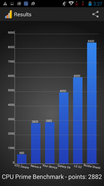
Solution
A good solution for this problem is to limit the size of the memory that Prime95 is allowed to use. Since the problem occurs because the FFT sizes are so large that they can’t even be stored in RAM, limiting the size of the RAM to your actual RAM will solve the issue. So, open up the dialog that asks you to select the test configurations. Make sure you have selected the Blend option and then select the Custom option. In the Custom option, you will see an option named “Memory to use”. Enter the size of your actual physical RAM (in MBs) that you have and run the test.
Custom
You also have the Custom option in Prime95. This option lets you play with some of the parameters of the tests and lets you make your own test. Here are the parameters that can be tweaked in this option
Min FFT size (in K): This is the minimum size of the FFTs. You will set the lower limit of the FFT sizes that the Prime95 will use. Keep in mind that the number you enter won’t be the same exact size but it will be multiplied by 1024. So, enter the numbers accordingly.
Max FFT size (in K): This will set the upper limit of the FFT sizes. Prime95 uses the min and max limits to cycle through all the FFTs within that range.
Note: Prime95 cannot go through a completely custom sizes. It has its own list of sizes that it can use. So, when you will set a range by entering numbers in min and max fields, Prime95 will go through all the numbers that will fall within the given range. So, keep the list in mind while entering the limits. Here is the list
8, 10, 12, 14, 16, 20, 24, 28, 32, 40, 48, 56, 64, 80, 96, 112, 128, 160, 192, 224, 256, 320, 384, 448, 512, 640, 768, 896, 1024, 1280, 1536, 1792, 2048, 2560, 3072, 3584, and 4096.
Prime95 will hang if the entered numbers aren’t from this list. So, make sure that the numbers you enter are from this list.
Run FFTs in-place: This option, if checked, forces the Prime95 to use the same portion of the RAM over and over again. This portion of the RAM will be selected based on the requirements of the calculations but the same portion will be over written for each calculation. If this option isn’t checked then the Prime95 will use all the RAM for its calculations.
Memory to use (in MB): This option will be available if the Run FFTs in-place option is disabled. This option sets the size of the RAM to be used for calculations.
Time to run each FFT size (in minutes): This option sets the time that the Prime95 should spend on a single FFT until it moves on to the next.
How long should I run Prime95 for?
Ideally, you should run Prime95 for 24 hours. 24 hours is viewed as a sufficient and a reliable time period to ensure there isnt anything missed by Prime95. Even if your PC didn’t crash or had an error after 12 hours that doesn’t mean it wouldn’t fail at the 18th hour. A lot of users have seen their systems fail at 18th or 20th hour. The 24 hours period is selected on the basis that it is the sufficient amount of time to run all the FFTs. It is obviously up to the user but we will recommend you to run Prime95 for 24 hours.
Which option to select?
The large in-place FFTs option is the one that stresses your CPU the most. This is mainly because the large size FFTs forces a lot of memory accesses. Although it’s an in-place testing which uses the same portion of the RAM for each calculation, the accesses are quicker and CPU doesn’t have to wait for the accesses as much as in the Blend configuration.
The Blend configuration comes at the second place when it comes to stressing the CPU. It falls a little behind the in-place large FFTs because you’re CPU have the whole RAM (and hard disk in worst cases) which means that it might have to wait for the RAM accesses. However, since the blend test accesses the whole RAM, a test fail in Blend configuration will indicate a problem with the RAM. But, keep in mind that Prime95 is not a RAM tester. It is a CPU stress tester. A test fail in Blend doesn’t necessarily means a RAM problem. It is an indicator that there might be a RAM problem. So, checking your RAM with a proper memory tester program is recommended.
The Small FFTs is at the bottom when it comes to stressing the CPU. It doesn’t make a lot of RAM accesses and doesn’t stresses the CPU at its maximum.
Note: Chips are known to get really hot when they are stressed and performing a lot of calculations. So, if a chip is really hot then it usually means it is really stressed. You can check the how much stress each of these configurations put on your CPU by keeping an eye on the CPU temperature as well.
Most of the people prefer the Blend configuration mainly because it checks both your RAM and your CPU. However, as mentioned above, Prime95 is not a RAM checker so don’t consider the Blend configuration as a proper RAM test. We will recommend using the in-place large FFTs configuration because it stresses CPU the most. The Blend configuration is also a very reasonable configuration for stress testing but it always have some chances of messing up with the results (see Blend configuration section above). Some beginners might miss that aspect of the stress testing. But, the choice is up to you. Whichever option suits you best. Each of these options have its own advantages and drawbacks.
How to use Prime95?
Go here and download the relevant version of Prime95 for the computer you want to stress test. Unzip the compressed folder, open it and run the file named prime95.exe. When the program launches, click on Just Stress Testing.
Select the FFT size configuration you want to use and then click on OK to start the stress test. If you don’t see a screen with Torture Test types then click Options and select Torture test…
When the test begins, Prime95 will open one worker thread for each logical CPU that the computer being tested has. These threads will continuously update the test information for every logical CPU in real time. If Prime 95 encounters an error while testing any logical CPU, all worker threads will stop and the thread for the logical CPU that the program encountered an error on will state that a hardware failure has been detected. You can learn more about the errors the Prime95 stress test comes across in the txt file that the program creates.
If no errors are detected, the Prime95 stress test will continue to run for as long as you want it to. To end the test at any time, all you need to do is click on Test in the window’s toolbar at the top and then click on Stop… in the contextual menu.
What if your test fails?
When you run Prime95, there can be two results. The first one is that your Prime95 runs fine and your computer doesn’t fail the stress test. This is very good and you can go back to your normal computer using routine. The second case is that your computer fails the test. In this case, there are a few things that you can do.
Check your RAM
If the test failed at small FFTs stress test then the RAM isn’t at the top of the suspect list. If the test failed at any of the other two configurations then we will recommend testing your RAM with a good memory testing program. You can use any program you want but if you aren’t sure then we will recommend the Memtestx86. Even if your computer failed the small FFTs test, we will recommend using a memory checker program just to be sure about the RAM. If you don’t have a memory checker program then click here and follow the steps in method 1. It is our own guide the helps you in using the Memtestx86 via step by step guide.
If you are wondering why the RAM check is more important on In-place FFTs or Blend configurations then that is because these two tests accesses RAM a lot more times than the small FFTs test. So, a fail in these test has a high likelihood to be caused by the RAM.
Heat Issues
Sometimes your PC might fail the test or hang or shuts down because of overheating. This usually happens in Large FFTs tests but can happen in other tests as well. Large FFTs cause this the most because they stress your CPU the most. As mentioned above, stressing your CPU will cause it to overheat and if your computer doesn’t have proper cooling systems then it can cause this problem as well. Even a dust clean up from your motherboard can cause a huge difference in the heat drop. So, try to clean up the computer, make sure the fan is running and proper cooling systems are in place. Also, check your heatsink as well.
There are also several temperature monitor programs that you can use to keep an eye on the temperature of your system. SpeedFan is one of these programs that is pretty accurate and is being used by many professionals.
Power Supply
Although rare but not impossible is that the fail might be because of the power supply. A lot of the times when your CPU is stressed, or utilized to its maximum capacity, it can cause your power supply to heat up in return. Power supplies can drop their voltage when they overheat which can cause this failure. In these type of cases, your computer will hang or crash. However, certain errors might also appear if the fail is caused by the power supply.
You won’t experience this on regular usage mainly because the CPUs aren’t utilized 100% especially if you use your computer for tasks that aren’t CPU intensive. However, if you play 3D videos games with a high end video card without experiencing this kind of problem then your power supply isn’t the suspect. This is because a video card draws a lot of power during a 3D game and if it were a power supply issue then you would have noticed this while playing a high end 3D game.
If you don’t perform any 3D high intensive tasks or you don’t have a video card or you have experienced this during 3D gaming then it’s worth checking your power supply. The solution for this is, unfortunately, to replace the power supply. You can try a power supply from another PC just to make sure if the problem really is related to the power supply or not. If the other power supply works fine then buy a new power supply for your system.
Other Options
Unfortunately, if the issue isn’t related to RAM or one of the other things that are mentioned above then it is pretty hard to pin point the exact problem. Prime95 will usually point you to the module that caused the fail but if it didn’t then it’s a very tiresome task to locate the issue.
In these kind of scenarios, your options are to start checking every section one by one. This is because a fail in CPU stress test isn’t necessarily caused by the CPU. There can be other things indirectly causing this fail like thermal issues (as mentioned above). You can check the BIOS settings and tweak the CPU voltages, speed, multipliers and several other things and check whether these settings solve the issue. Increasing the RAM volts or slowing its speed are also an option for you. A lot of people solve the issue by overvolting the RAM. If you don’t know about these options or you haven’t played with these settings then we will recommend you to get help from an IT specialist because these settings, if done incorrectly, can burn your CPU or cause a lot of serious problems.
What is the difference between CPU and GPU?
CPU and GPU are processors. There is much in common between them, but they were designed to perform different tasks. What exactly is the difference between CPU and GPU, you will learn from this article.
Note You are reading an improved version of an article we published earlier.
Contents:
- What is CPU
- What is GPU
- Difference between CPU and GPU
- Why GPU is used for mining and not CPU
What is a CPU
CPU is a central processing unit.
The main function is to execute a chain of instructions in the shortest possible time.
The CPU is designed to execute multiple threads at the same time, or split one thread of instructions into several and, after executing them separately, merge them back into one, in the correct order. Each instruction in a stream is dependent on those following it. That is why the CPU has so few execution units, and all the emphasis is on execution speed and reducing idle times, which is achieved using cache memory and a pipeline. nine0003
If you want to know not only what a CPU is, but also how a processor works, then read this article.
What is a GPU
A GPU is a graphics processing unit.
The main function is to render 3D graphics and visual effects.
The GPU receives polygons as input, and after performing the necessary mathematical and logical operations on them, it outputs pixel coordinates. In fact, the work of the GPU is reduced to operating on a huge number of tasks that are independent of each other. Therefore, it contains a huge number of execution units — in modern GPUs there are 2048 or more of them. nine0003
Difference between CPU and GPU
We’ve figured out the concepts, now let’s see what is the difference between CPU and GPU.
- Memory access . In the GPU, it is connected and easily predictable — if a texture element is read from memory, then after a while the turn of neighboring texels will come. The situation is similar with recording.
- Cache size . The GPU, unlike general purpose processors, does not need a large cache. Textures require only 128-256 kilobytes. nine0010
- Multithreading support . The central processor executes 1 – 2 computation threads per core, and the graphics processor can support several thousand threads per multiprocessor, of which there are several in a chip. And if switching from one thread to another for the CPU costs hundreds of cycles, then the GPU switches several threads in one cycle.
- Architecture . In the CPU, most of the chip area is occupied by instruction buffers, hardware branch prediction, and huge amounts of cache memory, while in the GPU, most of the area is occupied by execution units.
nine0010
Schematic representation of the CPU and GPU
Why GPU is used for mining, and not the CPU
If the CPU makes decisions in accordance with the instructions of the program, then the GPU performs a huge amount of the same type of calculations. It turns out that if you submit simple independent mathematical tasks to the graphics processor, then it will cope much faster than the central processor. This is successfully used by bitcoin miners.
The essence of mining is that computers solve mathematical problems, as a result of which bitcoins are created. All bitcoin transfers along the chain are transferred to miners, whose job it is to choose from millions of combinations a single hash that matches all new transactions and a secret key, which will provide the miner with a reward. The calculation speed directly depends on the number of execution units. Therefore, GPUs are more suitable for this type of task than CPUs. The greater the number of calculations made, the higher the chance of getting bitcoins. nine0003
Advertising on Tproger: we will find developers of the right stack and level for you.
More
Download
SUSP — Main Processor — Haas Service Manual
- Main Processor Board — Replacement
- Main Processor Battery — Replacement
- Main Processor Board — Troubleshooting
Introduction
This procedure will show you how to replace the Main I/O Control Board on a New Generation Control Machine (NGC). nine0003
Main Control PCB Replacement Kits:
- 93-32-4250B SUSP MAIN BOARD (1 GB) REPLACE
- 93-32-4251B SUSP MAIN BOARD (32 GB OR 64 GB) REPLACE
- 93-2796 SUSP MAIN BOARD (1 GB) REPLACE
- 93-2799 SUSP MAIN BOARD (32 GB, 64 GB) REPLACE
- 93-3427 SUSP BASIC PROCEDURE WITH REPLACEMENT C7 1GB
- 93-3428 SUSP BASIC PROCEDURE WITH REPLACEMENT C7 32/64GB
- 93-1000310 EXPANDED MEMORY 32 GB (PCB+SD+CODE)
- 93-1000309 EXPANDED MEMORY 64 GB (PCB+SD+CODE)
Replacement
1
Press [POWER OFF] . Set the main switch to the OFF position. Lock the main switch. Use an approved lock with an approved security tag.
Danger: After turning off the machine, wait at least 5 minutes before working in the control cabinet to allow the supplied power to dissipate. Wait for the voltage indicator LED on the vector disk to go off completely. nine0003
Attention! Attention! An ESD strap must be worn when handling the main control board.
2
Disconnect all cables from the main control board
Note: Place an identification tag on each cable that attaches to the PCB. This simplifies installation.
Remove the used main control board.
Install a new main control board.
Connect cables. Use identification marks to connect cables. nine0003
Software download
You need to «re-install» the software when replacing the main control board. See Updating Software” — (Option 5) New installation — SUSP.
Memory upgrade activation
32 GB or 64 GB memory upgrade kits require an activation code to activate the memory in the control system. Refer to Option — Activation Code Only — SUSP. nine0003
Introduction
This procedure shows how to replace the button cell battery on the SUSP main processor.
Parts required
- CR2032 button cell Li-ion battery
Electrical Safety:
Caution: When servicing or repairing CNC machines and their components, you should always follow basic safety precautions. This reduces the risk of injury and mechanical damage. nine0175
- Set the main circuit breaker to position [OFF] .
Hazard: Before doing any work inside the control cabinet, ensure that the high voltage indicator light located on the 320V Power Supply / Vector Drive has been turned off for at least 5 minutes.
Some maintenance procedures may be hazardous or life threatening. DO NOT attempt procedures that you do not fully understand. If you have any doubts about the procedure, contact your HAAS Dealership and schedule a service visit. nine0003
Removing the battery
Press lightly on the back of the battery.
Caution: The battery holder [1] may be damaged if the battery is allowed to move during the next step.
Position the small flat screw of the driver under the battery on the side of the spring retainer and carefully pry under the battery to remove the battery.
Battery installation
Remove the protective film from the new battery.
Install a new battery, make sure the «+» symbol faces up.
Place one end of the battery in the holder against the metal spring, pulling the battery slightly into the metal spring. Carefully press back the battery yoke down into the past tabs holder.
Important: Do not replace the processor if the battery holder tabs [1] are broken. Temporarily hold the battery in place and apply hot silicon glue to keep the battery charged.
Note. Avoid soiling the contact points of the battery holder with silicone.
Set machine date and time. Link to Next Generation Control — Date/Time Change of the Procedure.
Introduction
Use this document to troubleshoot the Maincon PCB on a machine with a next generation control system. If you cannot find a script that matches your situation, please submit an error log ( [SHIFT] + [F3] ) to [email protected]
Note : If necessary, the error log command ( [SHIFT] + (F3) ) can be initiated during program execution.
Before replacing any parts, download and complete the Main Processor Circuit Board Inspection Report Checklist below.
Main Processor PCB Inspection Report Checklist
{{ if (!videoId) { }}
{{ } else { }}
{{ if (wistiaId) { }}
{{ } else { }}
{{ } }}
{{ } }}
Main Processor Board — Overview
Next generation Main Control Processor PCB includes blocks for video, main and motion controller. It accommodates 16 motion control channels. There is no need to add additional MOCONs for applications that require more channels. This board communicates with I/O PCB via serial communication through one RJ45 cable using RS422 system. Next generation control includes ports for linear scale encoders. Communication with the front panel is via an RJ45 cable and includes video signals for the LIQUID display. nine0175
- J3 is the power input connector, where +5 Vdc current and +/- 12VDC. current, as well as a voltage control signal comes from the PSUP board.
- J7 is an RJ45 Ethernet connector and dual USB hub.
- The RJ45 Ethernet connector is an input from the control cabinet side panel stamped panel for a wired Ethernet connection.
- The top USB port is connected to the SKBIF board on J9 .
- The bottom USB port is not currently in use. nine0010
- J8 is a dual USB hub. It is currently not in use.
- J9 is an Ethernet RJ45 connector. It is connected to the SKBIF board at J28 .
- J14 is an RJ45 Ethernet connector. It is connected to the I/O board at J4 .
- Currently J13 not in use.
- J2 is an RP-SMA coaxial connector (version A for reverse polarity subminiatures). It is connected to a Wi-Fi antenna. nine0010
- J16 is the voltage control input from the vector drive.
- P1 — P16 are amplifier command connections. They connect to the axis servo amplifiers.
- P17 — P32 — Axis encoder input connections. These are inputs for axle servo position sensors, axle home sensors, and some rotator air pressure sensors.
- P33 — P37 are scalable axis encoder inputs. They are connected to auxiliary scalable encoders.
- BT1 is a system battery. It provides power to store the date and time memory.
- Q7 Module is a processor board. This module should not be removed.
- J12 is the USB connector of the WiFi module. It is connected to the circuit board of the WiFi module.
- J20 is a UMCC (Ultra Miniature Coaxial Connector). It connects to the WiFi module with a jumper. nine0010
Main Processor PCB Troubleshooting — Loading
1
When the machine is powered on, the control screen does not load and displays a black screen and the LCD backlight is off.
Check the following:
- Check the power input connector on J3 and measure +5 Vdc. current at the connector. The correct voltage will be between +4.90 Vdc and +4.90 Vdc. up to +5.20 VDC current.
- Switch the machine off/on several times and check that the measured voltage remains unchanged. nine0010
- If voltage levels are inconsistent. Troubleshoot the PSUP PCB, LVPS and cables to find the power issue.
Attention! When testing for voltage, be careful not to short the red and black wires. This may damage the main processor circuit board or the low voltage power supply.
2
If you consistently measure the correct voltage at boot, but the control system does not boot and the screen is black. Check the following with the machine power off:
- Check the RJ45 Ethernet cable and connector from the main processor board at J9 to the SKBIF board at J28. Test the cable, refer to the Network Cable — Tester Tool procedure.
- Check LCD connections. LCD data cable at J16 on SKBIF to LCD. LCD backlight cable from J13 to LCD. Do not disable connections, but make sure they are fully connected.
Machine power on:
- Check the power input connector at J20 and measure the voltage at the +3.3 Vdc test points. +5 VDC +12 VDC current on SKBIF. The correct voltage will be between +3.10 Vdc and +3.10 Vdc. up to +3.50 VDC from +4.90 VDC up to +5.20 VDC from +11.85 Vdc up to +12.40 VDC current.
3
If the cable connections and measured voltage are correct, but the control system does not boot and the screen is black. Do the following:
- Update the machine software by holding the U button while turning on the machine.
- USB stick must have service key, latest software and machine configuration.
- If the machine boots up and you see the Haas software update screen. Perform software update Option 2.
- If this fails, perform a software update for Option 5.
- If this fails, perform a RESTORE SOFTWARE UPDATE by holding the E button while turning on the power to the machine. Then it will boot from USB, not from the processor. nine0010
- If the machine does not boot and the display shows the Haas software update screen. Replace the main processor board.
4
If the control screen turns on but stops in steps 2-8, it is not a power or RJ45 video connection issue, but a main processor load issue.
This can happen every time you boot or intermittently. Check the following:
- Check the Main Processor/Software Compatibility Table below and update the software to the latest version.
nine0010
Note: Do not update current software from software version 100.16.000.1020 or lower. First you need to update the software to version 100.16.000.1021, then you can upgrade to the current software version.
- Perform software update Option 2 first.
- If this fails, perform an Option 5 software update. If this fails, perform a RECOVERY SOFTWARE UPDATE while holding the E button while turning on the power to the machine. nine0010
- If the machine does not boot and the display shows the Haas software update screen. Replace the main processor board.
Hardware and Software Compatibility Chart
Note: Do not update to current software from software version 100.16.000.1020 or below . You need to update to 100.16.000.1021 first you can upgrade to the current version of the software. nine0175
Symptom table
PCB component inspection
Intermittent symptoms or alarms may be caused by a component failure. Below is a list of possible failures:
- Missing solder on some or all of the contact components
- Poor solder
- Solder bridges
- Wrong component installation (orientation)
- Missing components
Note: Some PCBs have unused schematics and are missing components intentionally, look for torn off components.
- Broken components
- Broken pins on IC
- Bent pins on connectors
Use a magnifying glass to inspect the circuit components on the front and back of the Maincon PCB. Below are the circuit component areas to inspect:
- Inspect for bent pins inside connectors, also look for loose header connectors. nine0010
- Check for loose battery, broken battery, repair if necessary.
Note: Do not replace Maincon PCB. Link to Next Generation Control — PCB Master Control — Battery Replacement for repair instructions.
- Inspect for bent or missing pins inside connectors, also look for loose header connectors.