User cpu: CPU UserBenchmarks — 1369 Processors Compared

What specifically are wall-clock-time, user-cpu-time, and system-cpu-time in Unix?


Asked


Modified
19 days ago


Viewed
110k times

I can take a guess based on the names, but what specifically are wall-clock-time, user-cpu-time, and system-cpu-time in Unix?

Is user-cpu time the amount of time spent executing user-code while kernel-cpu time the amount of time spent in the kernel due to the need of privileged operations (like I/O to disk)?

What unit of time is this measurement in?

And is wall-clock time really the number of seconds the process has spent on the CPU or is the name just misleading?

  • unix
  • operating-system


1

Wall-clock time is the time that a clock on the wall (or a stopwatch in hand) would measure as having elapsed between the start of the process and ‘now’.

The user-cpu time and system-cpu time are pretty much as you said — the amount of time spent in user code and the amount of time spent in kernel code.

The units are seconds (and subseconds, which might be microseconds or nanoseconds).

The wall-clock time is not the number of seconds that the process has spent on the CPU; it is the elapsed time, including time spent waiting for its turn on the CPU (while other processes get to run).


6

Wall clock time: time elapsed according to the computer’s internal clock, which should match time in the outside world. This has nothing to do with CPU usage; it’s given for reference.

User CPU time and system time: exactly what you think. System calls, which include I/O calls such as read, write, etc. are executed by jumping into kernel code and executing that.

If wall clock time < CPU time, then you’re executing a program in parallel. If wall clock time > CPU time, you’re waiting for disk, network or other devices.

All are measured in seconds, per the SI.

time [WHAT-EVER-COMMAND]

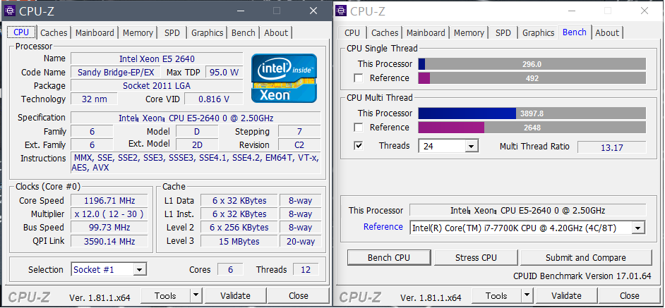
real    7m2.444s
user    76m14.607s
sys 2m29.432s
$ lscpu
Architecture:          x86_64
CPU op-mode(s):        32-bit, 64-bit
Byte Order:            Little Endian
CPU(s):                24

real or wall-clock

real 7m2.444s

On a system with a 24 core-processor, this cmd/process took more than 7 minutes to complete. That by utilizing the most possible parallelism with all given cores.

user

user 76m14.607s

The cmd/process has utilized this much amount of CPU time.

In other words, on machine with single core CPU, the real and user will be nearly equal, so the same command will take approximately 76 minutes to complete.

sys

sys 2m29.432s

This is the time taken by the kernel to execute all the basic/system level operations to run this cmd, including context switching, resource allocation, etc.

Note: The example assumes that your command utilizes parallelism/threads.

Detailed man page: https://linux.die.net/man/1/time


2

Wall clock time is exactly what it says, the time elapsed as measured by the clock on your wall (or wristwatch)

User CPU time is the time spent in «user land», that is time spent on non-kernel processes.

System CPU time is time spent in the kernel, usually time spent servicing system calls.


Sign up or log in

Sign up using Google

Sign up using Facebook

Sign up using Email and Password

Post as a guest

Email

Required, but never shown

Post as a guest


Email

Required, but never shown


performance — Why real time is much higher than «user» and «system» CPU TIME combined?

We have a batch process that executes every day. This week, a job that usually does not past 18 minutes of execution time (real time, as you can see), now is taking more than 45 minutes to finish.

Fullstimmer option is already active, but we don’t know why only the real time was increased.

In old documentation there are Fullstimmer stats that could help identify the problem but they do not appear in batch log. (The stats are those down below: Page Faults, Context Switches, Block Operation and so on, as you can see)

It might be an I/O issue. Does anyone know how we can identify if it is really an I/O problem or if it could be some other issue (network, for example)?

To be more specific, this is one of the queries that have increased in time dramatically. As you can see, it is reading from a data base (SQL Server, VAULT schema) and work and writing in work directory.

Number of observations its almost the same:

We asked customer about any change in network traffic, and they said still the same.
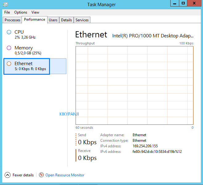
Thanks in advance.

  • performance
  • debugging
  • optimization
  • sas
  • enterprise-guide


3

For a process to complete, much more needs to be done than the actual calculations on the CPU.

  • Your data has te be read and your results have to be written.
  • You might have to wait for other processes to finish first, and if your process includes multiple steps, writing to and reading from disk each time, you will have to wait for the CPU each time too.

In our situation, if real time is much larger than cpu time, we usually see much trafic to our Network File System (nfs).

As a programmer, you might notice that storing intermediate results in WORK is more efficient then on remote libraries.

You might safe much time by creating intermediate results as views instead of tables, IF you only use them once. That is not only possible in SQL, but also in data steps like this

data MY_RESULT / view=MY_RESULT;
    set MY_DATA;
    where transaction_date between '1jan2022'd and 30jun2022'd;
run;


Sign up or log in

Sign up using Google

Sign up using Facebook

Sign up using Email and Password

Post as a guest

Email

Required, but never shown

Post as a guest


Email

Required, but never shown


Lecture 2.

Processor. Processor operating modes. CPU user registers.

2.1. CPU.

Most
The main element of a computer is, of course, the processor. Let’s detail it
consider. Simplified structure of the processor (Fig. 4):

4. Simplified structure of CPU

Main
processor elements:

Registers are special memory locations
physically located inside the processor. Unlike RAM, where to access
for data it is required to use the address bus, for registers the processor can
contact directly. This will significantly speed up the work with the data.

Arithmetic logic
device

performs arithmetic operations such as addition, subtraction, and
logical operations.

Block
control

defines the sequence of microinstructions executed during the processing of machine
codes (commands).

Clock
generator
, or generator
clock pulse
, sets the operating frequency of the processor.

2.2. Processor operating modes.

Processor
x86 architecture can work in one of five modes and switch between
them very quickly:

1.
Real
(unprotected) mode (real address mode) — the mode in which the 8086 processor worked.
In modern processors, this mode is supported mainly for compatibility.
with ancient software (DOS programs).

2.
Protected
protected mode — a mode that was first implemented in the 80286 processor. All modern operating systems
(Windows, Linux, etc.) run in protected mode. Real Mode Programs
cannot function in protected mode.

3.
Mode
virtual processor 8086 (virtual-8086 mode, V86) — in this mode, you can
switch only from protected mode. Serves to provide
functioning of programs of real
mode, and allows
simultaneous operation of several such programs, which is impossible in real mode. V86 mode provides
hardware to form a virtual machine that emulates the 8086 processor. Virtual
the machine is formed by software
means of the operating system.
In Windows, such a virtual machine is called VDM (Virtual DOS Machine —
DOS virtual machine). VDM intercepts and processes system calls from running DOS applications.

4.
Unreal
mode (unreal mode, aka big real mode) — similar to real mode, only
allows you to access all physical memory, which is impossible in real
mode.

5.
Mode
system management System Management Mode (SMM) is used in office and
debugging purposes.

At
booting the computer, the processor is always in real mode, in this
mode worked first
operating systems such as MS-DOS, but modern operating systems
such as Windows and Linux translate
processor in protected mode. You are probably wondering what protects the processor in
protected mode? In protected mode, the processor protects running programs
in memory from mutual influence (intentionally or by mistake) on each other, which
can easily happen in real life. That’s why protected mode is called
protected.

2.3. Processor registers
(software model of the processor).

For
understanding how assembler commands work, it is necessary to clearly understand how
data is addressed, which processor registers and how can
be used when executing instructions. Consider the basic programming model
Intel 80386 processors, which includes:

eight
general purpose registers for storing data and pointers;

registers
segments — they store 6 segment selectors;

register
management and control EFLAGS, which allows you to manage the state of the execution
program and state (at the application level) of the processor;

pointer register
EIP of the next processor instruction to be executed;

system
commands (instructions) of the processor;

modes
addressing data in processor instructions.

Let’s start
from the description of the basic registers of the Intel 80386 processor.

Basic
The registers of the Intel 80386 processor are the basis for developing programs and
allow you to solve basic data processing tasks. All of them are shown in Fig.
5.

Fig.
5. Intel CPU base registers 80386

Among
of the basic set of registers, we single out separate groups and consider their purpose.

2.4. General registers.

32-bit
registers EAX (battery), EBX (base), ECX (counter), EDX (data register)
can be used without restrictions for any purpose — temporary storage
data, arguments, or results of various operations. Register names
come from the fact that some commands apply them in a special way:
for example, an accumulator is often needed to store the result of actions performed
over two operands, the data register in these cases gets the high part
result, if it does not fit into the accumulator, the register-counter works as
counter in loops and string operations, and register-base — with the so-called
base addressing. The lower 16 bits of each of these registers are used as
independent registers with the names AX, BX, CX, DX. In fact, in processors
8086 — 80286 all registers were 16-bit and were called that way, and 32-bit
EAX-EDX appeared with the introduction of the 32-bit architecture in the 80386. In addition,
individual bytes in 16-bit registers AX — DX can also be used as
8-bit registers and have their own names. The upper bytes of these registers are called
AN, VN, CH, DH, and the younger ones — AL, BL, CL, DL (see Fig. 4.1).

Others
four registers — ESI (source index), EDI (destination index), EUR (pointer
bases), ESP (stack pointer) — have a more specific purpose and apply
to store all sorts of temporary variables. The ESI and EDI registers are required in
string operations, EUR and ESP — when working with the stack. Just as in the case with
registers EAX — EDX, the lower halves of these four registers are called SI,
DI, BP and SP, respectively, and in processors up to 80386 only they and
were present.

2.5. segment registers.

using segmented memory models to form any address you need
two numbers — the address of the beginning of the segment and the offset of the desired byte relative to this
start (in the segmentless flat memory model, the addresses of the start of all segments are equal).
Operating systems (other than DOS) can host segments that the
user program, in different memory locations and even temporarily write them to
disk if there is not enough memory. Since segments can be anywhere,
the program refers to them, using instead of the real address of the beginning of the segment
A 16-bit number called a selector. Intel processors have six
16-bit registers — CS, DS, ES, FS, GS, SS where selectors are stored.
(The FS and GS registers were absent in the 8086, but appeared already in the 80286.) This
means that at any time you can change the parameters recorded in these
registers.

B
different from DS, ES, GS, FS which are called data segment registers, CS and
SSs are responsible for two special types of segments, the code segment and the stack segment.
The first contains the program that is currently executing, hence the entry
a new selector to this register causes the following to be executed not
the command following in the text of the program, and the command from the code located in another
segment, with the same offset. Offset of the next executable command always
stored in a special register EIP (instruction pointer, 16-bit form of IP),
writing to which will also lead to the fact that some
another team. In fact, all control transfer commands are transitions,
conditional jump, loop, subroutine call, etc. — and carry out this
the very entry in CS and EIP.

2.6. Flag register.

More
one important register that is used when executing most commands is
flag register. As before, its lower 16 bits, which represented the entire
this register prior to the 80386 processor are called FLAGS. In EFLAGS every bit
is a flag, i.e. set to 1 under certain conditions, or
setting it to 1 changes the behavior of the processor. All flags located in
the high word of the register, are related to protected mode control,
therefore, only the FLAGS register is considered here (see Fig. 6):

Fig. 6. Register of flags FLAGS.

CF – carry flag. Set to 1,
if the result of the previous operation did not fit in the receiver and a transfer occurred
from the most significant bit or if borrowing is required (when subtracted), otherwise —
to 0. For example, after adding the word 0FFFFh and 1, if the register to which
put the result, — a word, it will be written 0000h and the flag CF = 1.

PF — parity flag. Set to 1,
if the low byte of the result of the previous instruction contains an even number of bits,
equal to 1, and to 0 if odd. This is not the same as divisibility by two. Number
is divisible by two without a remainder if its least significant bit is zero, and not
is divisible when it is 1.

AF — half-carry flag or
auxiliary transfer. Set to 1 if as a result of the previous
operation, a carry (or borrow) has occurred from the third bit to the fourth. This flag
used automatically by BCD commands.

ZF — zero flag. Installed in
1 if the result of the previous command is zero.

SF — sign flag. He is always equal to the elder
result bit.

TF — trap flag. He was
provided for debuggers that do not use protected mode. Installation
set to 1 causes that after the execution of each program instruction
control is temporarily transferred to the debugger.

IF — interrupt flag. Reset this flag to 0
causes the processor to stop processing interrupts from external
devices. It is usually reset for a short time to perform critical
sections of code.

DF
— flag
directions. It controls the behavior of string processing commands: when it
set to 1, the lines are processed in the direction of decreasing addresses, when DF=0 — vice versa.

OF – overflow flag. He
is set to 1 if the result of the previous arithmetic operation on
signed numbers are out of range. For example, if at
adding two positive numbers gives a number with the most significant bit equal to
unity, i.e. negative, and vice versa.

Flags
IOPL (I/O Privilege Level) and NT (Nested Task) apply in
protected mode.

2.7. Command execution cycle

Program
consists of machine instructions. The program is loaded into RAM
computer. Then the program begins to execute, that is, the processor executes
machine instructions in the order in which they are written in the program.

For
so that the processor knows which instruction to execute at a certain moment,
exists program counter — a special register that stores
the address of the command to be executed after the execution of the current command.
That is, when the program is started, the address of the first instruction is stored in this register. AT
Intel processors as a program counter (it is also called pointer
command
) uses the EIP register (or IP in 16-bit programs).

Counter
commands works with scratch memory, which is located inside
processor. This memory is called command queue where to put
one or more commands just before they are executed. That is, in
The command counter stores the address of the command in the command queue, not the address of the operational
memory.

Cycle
execute command

is a sequence of actions performed by the processor when
executing one machine instruction. When executing each machine instruction
The processor must perform at least three steps: fetch, decode, and
performance. 
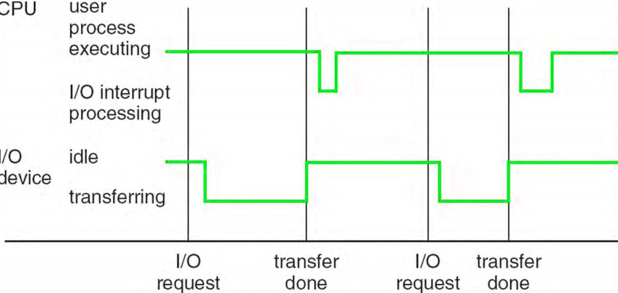
If the instruction uses an operand located in the operational
memory, then the processor will have to perform two more operations: fetching an operand from
memory and write the result to memory. These five operations are described below.

  • Command fetch . The control unit extracts
    command from memory (from the command queue), copies it to internal memory
    processor and increases the value of the program counter by the length of this instruction
    (different commands may have different sizes).
  • Decode command . The control unit determines
    the type of instruction being executed, sends the operands specified in it to the ALU, and
    generates ALU electrical control signals that correspond to
    the type of operation being performed.
  • Select operands . If the command uses
    operand located in RAM, the control unit starts
    operation to fetch it from memory.
  • Execute command . ALU performs the specified in
    operation command, saves the result in the specified location and
    updates the state of the flags, by the value of which the program can judge about
    result of command execution.
  • Write result to memory . If the result of the execution
    commands must be stored in memory, the control unit starts the operation
    storing data in memory.

Summarize
obtained knowledge and compose a command execution cycle:

  1. Select a command from the command queue,
    pointed to by the program counter.
  2. Determine the address of the next instruction in
    command queue and write the address of the next command to the command counter.
  3. Decode command.
  4. If the instruction contains operands,
    in memory, then select the operands.
  5. Run command and install
    flags.
  6. Write result to memory (according to
    need).
  7. Start next command
    from point 1.

This
simplified command execution loop. In addition, actions may differ in
processor dependencies. However, it does give a general idea of ​​how
The processor executes one machine instruction, and hence the program as a whole.

User mode and kernel mode — Windows drivers

Twitter

LinkedIn

Facebook

E-mail address

  • Article
  • Reading takes 2 minutes

The processor on a Windows-based computer has two different modes: user mode and kernel mode .

The processor switches between two modes depending on the type of code running on the processor. Applications run in user mode, while core operating system components run in kernel mode. Although many drivers run in kernel mode, some drivers can run in user mode.

User mode

When you run an application in user mode, Windows creates process for the application. The process provides the application with a private virtual address space and a private descriptor table . Because the application’s virtual address space is private, one application cannot modify data owned by another application. Each application runs in isolation, and if the application fails, the failure is limited to one application. Other applications and the operating system are not affected by the crash.

In addition to the private, the user mode application’s virtual address space is limited. A process running in user mode cannot access virtual addresses reserved for the operating system. Restricting the application’s virtual address space in user mode prevents modification and possibly corruption of critical operating system data.

Kernel mode

All code that runs in kernel mode uses the same virtual address space. Thus, a kernel-mode driver is not isolated from other drivers and from the operating system itself. If a kernel-mode driver accidentally writes data to the wrong virtual address, data that belongs to the operating system or another driver may be compromised.