USB Connector and Cable Type Guide
- Home
- USB Connector Type Guide
Ubiquitous to modern society, USB tech can be found in at least one or more devices people use on a daily basis. However, USB cables come in a variety of connections, most of which are incompatible with the others. This makes replacing a USB cable a troublesome task, especially when the differences between each may seem trivial to the inexperienced.
For instance, while micro B and mini USBs may use synonymous terms, you cannot simply use one plug to connect to the other’s port. To make matters even more confusing, the USB tech industry is constantly evolving that even the same plug type can differ between each version of USB, simultaneously influencing the plug’s performance.
We have put together this exhaustive guide to help you untangle all the nuanced idiosyncrasies between the different types of USB cables on the market.
Also known as USB standard A connector, the USB A connector is primarily be used on host controllers in computers and hubs. USB-A socket is designed to provide a «downstream» connection intended for host controllers and hubs, rarely implemented as an «upstream» connector on a peripheral device. This is because USB host will supply a 5V DC power on the VBUS pin. As such, it is important to remember while purchasing USB cables it is safest to make sure at least one of the plugs is a USB A.
Though not that common, USB A male to A male cables are used by some implementers to make connections between two USB A style female port. Be aware that typical A-A cables are not intended for connection between two host computers or computer to hub.
Related Products:
- USB 2.0 A to A Female Cables
- USB 2.0 A to B Cables
- USB 2.0 A to Mini B Cables
- USB 2.0 A to Micro B Cables
- USB 2.0 A to A Angle Cables
- USB 2.0 A to B Angle Cables
- USB 2.0 A to Mini B Angle Cables
- USB 2.0 A to Micro B Angle Cables
- USB 2.0 A to B Locking Cables
- USB 2.
 0 A to Mini B Angle Cables
- USB 2.0 A Female to A Cables
- USB 2.0 A Female to Crimp Housing Cables
- USB 2.0 A to B High Flex Cables
Also known as USB standard B connector, the B style connector is designed for USB peripherals, such as printer, upstream port on hub, or other larger peripheral devices. The primary reason for the development of USB B connectors were to allow the connection of peripheral devices without running the risk of connecting two host computers to one another. USB B type connector is still used today, though it is slowly being phased out in favor of more refined usb connector types.
Related Products:
- USB 2.0 A to B Cables
- USB 2.0 A to B Angle Cables
- USB 2.0 A to B Locking Cables
- USB 2.0 A to Mini B Angle Cables
- USB 2.0 B Female to B
- USB 2.0 B Female to 5 Pin Cables
USB-C or USB Type-C connector is the newest USB interface came to the market along with the new USB 3.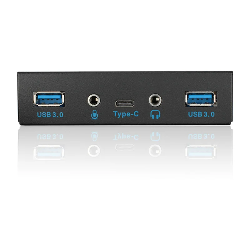 1 standard. Different from previously mentioned USB A type and B type connector, USB C Type connector can be used on both host controller ports and devices which use upstream sockets. In the last few years a numbers of laptops and cellphones have appeared on the market with C style USB connectors.
USB Type C connector is compatible with USB 2.0, 3.0, 3.1 Gen 1 and Gen 2 signals. A full feature USB 3.1 Gen 2 C to C cable is able to transmit data at maximum 10 Gbps with enhanced power delivery of up to 20V, 5A (100W) and to support DisplayPort and HDMI alternate mode to transfer video and audio signal.
Related Products:
- USB-C to USB-C Cables
- USB 3.0 to USB-C Cables
Similar to USB B type connector, USB mini B sockets are used on USB peripheral devices, but in a smaller form factor. The mini B plug by default has 5 pins, including an extra ID pin to support USB On-The-Go (OTG), which allows mobile devices and other peripherals to act as a USB host.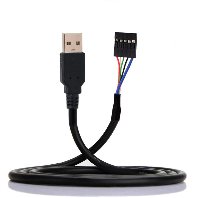
Initially, this plug was designed for earlier models of smartphones, but as smartphones have become more compact and with sleeker profiles, the Mini USB plug has been replaced by the micro USB. Now, the Mini-B is designed for some digital cameras while the rest of the mini plugs series have become more of a legacy connectors as they are no longer certified for new products.
Related Products:
- USB 2.0 A to Mini B Cables
- USB 2.0 Mini A to Mini B Cables
- USB 2.0 Mini B to Mini B Cables
- USB 2.0 Mini B to Mini B Female Cables
- USB 2.0 Mini A to Mini B Angle Cables
- USB 2.0 A to Mini B Locking Cables
- USB 2.0 A to Mini B High Flex Cables
- USB 2.0 Mini B to Mini B High Flex Cables
The micro USB B connector essentially a scaled down form of the mini USB which allowed mobile devices to get slimmer while still maintaining the ability to connect to computers and other hubs.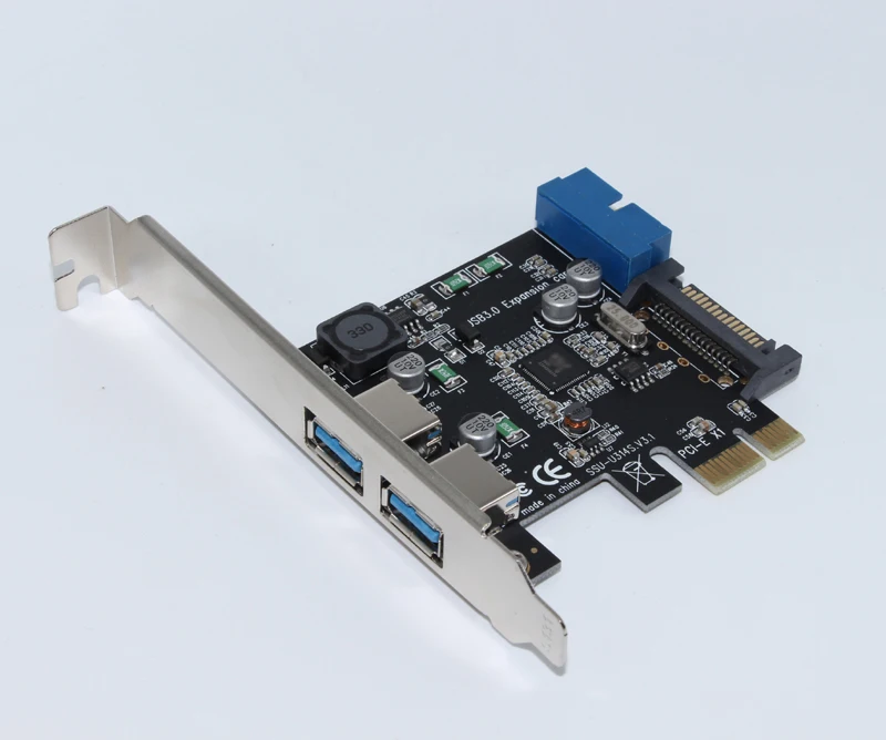
The micro B type connector holds 5 pins to support USB OTG, which permits smartphones and other similar mobile devices to read external drives, digital cameras, or other peripherals as a computer might. Note that to enable OTG feature, special wiring connection needs to be implemented in the cable assembly.
On Oct. 22, 2009, the international Telecommunication Union (ITU) announced to include Micro-USB interface into the Universal Charging Solution (UCS) that has been adopted broadly by industry.
Related Products:
- USB 2.0 A to Micro B Cables
- USB 2.0 A to Micro B Angle Cables
Inheriting the same design to the A-Type connector used in USB 2.0 & USB 1.1 application, USB 3.0 A is also provides a «downstream» connection that is designed for use only on host controllers and hubs.
However, USB 3.0 Type A processes additional pins that are not in the USB 2.0 A Type. USB 3.0 connector is designed to support 5Gbps bandwidth «SuperSpeed» data transfer, whereas, lower data rate can be transmitted with backward compatibility to USB 2.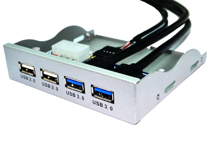 0 ports. USB 3.0 connectors are often in blue color or with «SS» logo to help distinguish them from previous generations.
Related Products:
- USB 3.0 A to B Active Cables
- USB 3.0 A to A Female Active Cables
- USB 3.0 A to Micro B Active Cables
- USB 3.0 A to Micro B Cables
- USB 3.0 A to B Cables
- USB 3.0 A to A Female Cables
- USB 3.0 A to A Cables
- USB 3.0 A to Micro B Angle Cables
- USB 3.0 A to B Angle Cables
- USB 3.0 A to Micro B Locking Cables
- USB 3.0 A to B Locking Cables
- USB 3.0 A to A Locking Cables
- USB 3.0 A to A Panel Mount Cables
- USB 3.0 A to 20 Pin Panel Mount Cables
- USB 3.0 A to Micro B Panel Mount Cables
- USB 3.0 A to B High Flex Cables
- USB 3.0 A to Micro B High Flex Cables
- USB 3.0 A to Micro B Ultra Slim Cables
- USB 3.0 A to A Water Proof Cables
USB 3.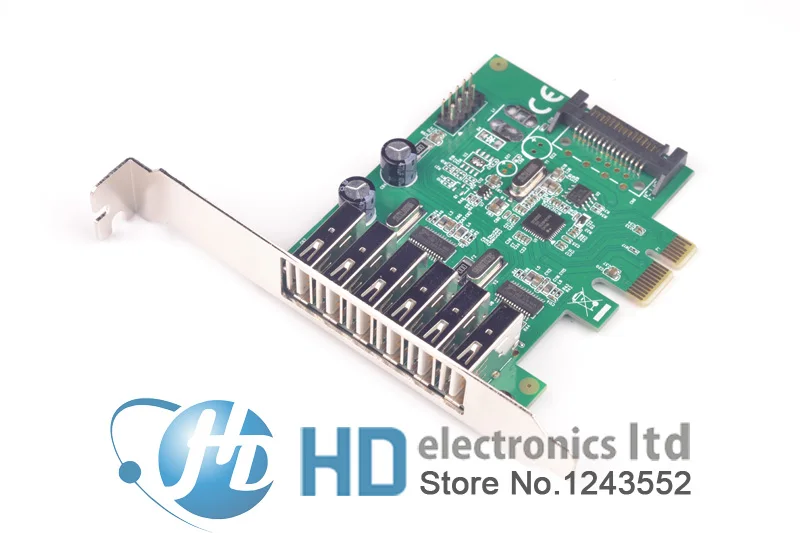 0 B-Type connector is designed for USB peripherals, such as printer, upstream port on hub, or other larger peripheral devices. This connector can support USB 3.0 SuperSpeed application and also carry USB 2.0 low speed data in the same time.
A USB 3.0 B plug cannot be plugged in to a USB 2.0 B socket due to its plug shape change. However devices with USB 3.0 Type B receptacles can accept mating with previous USB 2.0 B Type male plugs.
Related Products:
- USB 3.0 A to B Cables
- USB 3.0 A to B Angle Cables
- USB 3.0 A to B Locking Cables
- USB 3.0 B to B Panel Mount Cables
- USB 3.0 A to B High Flex Cables
Also referenced as the SuperSpeed Micro USB B connector, this connector stacks five more pins on the side of the USB 2.0 Micro B connector to achieve the full USB 3.0 standard data transfer speed. USB 3.0 Micro B connectors are found on hard drives, digital cameras, cell phones, and other USB 3.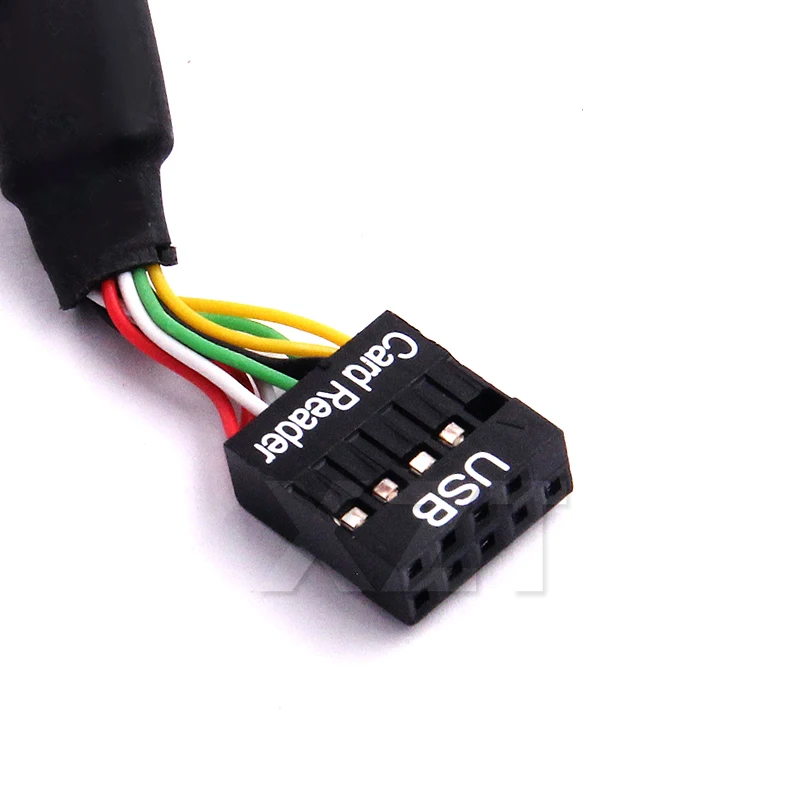 0 devices.
A USB 3.0 Micro B male connector cannot be plugged in to a USB 2.0 B socket due to its plug shape change. However devices with USB 3.0 Micro B receptacle can accept mating with previous USB 2.0 Micro B male plug.
With the growing need of higher data transfer rates, more industrial applications such as Machine Vision and 3D imaging are starting to implement USB 3.0 Micro B into their system designs. Screw lock Micro B connectors are often used in cabling to ensure secure interconnection.
Related Products:
- USB 3.0 A to Micro B Active Cables
- USB 3.0 A to Micro B Cables
- USB 3.0 A to Micro B Angle Cables
- USB 3.0 A to Micro B Locking Cables
- USB 3.0 A to Micro B Panel Mount Cables
- USB 3.0 A to Micro B High Flex Cables
- USB 3.0 A to Micro B Ultra Slim Cables
Developed by Intel, USB 3.0 internal connector cables are usually used to connect the external USB SS ports on the front panel to the motherboard.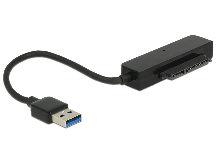 The 20 pin internal socket contains two lines of USB 3.0 signal channels, which allows maximum two individual USB 3.0 ports without sharing one channel data bandwidth.
Related Products:
- USB 3.0 A to 20 Pin Panel Mount Cables
Developed by Intel, USB 3.1 internal connector cables are designed for connecting motherboard to front panel USB ports.
Similar to previous USB 3.0 internal connector, the new generation internal connector also has a 20 pin header version that support single Type C port or dual Type A connections but with a reduced form factor and stronger mechanical latch design. An 40 pin header version internal connector was also introduced to support two full feature Type-C ports.
What are USB Headers? 2.0 vs 3.0 vs 3.1 vs 3.2 Headers
If you are new to PC building then trying to understand the different headers can get a bit daunting. Basically, a motherboard typically has several different headers (connectors) for connecting various devices.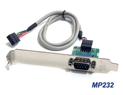 One such header type are the USB headers. So what are USB Headers?
USB headers are basically the physical connectors found on the motherboard for connecting the extra USB ports found on the PC case.
There are different types of USB headers intended for different versions of USB ports on the PC case. So for instance, a USB 2.0 header is different from a USB 3.0 header.
In the following article I will talk in detail about USB headers, their different types, but first let us talk about the different USB versions because they are atrociously confusing to the uninitiated.
TABLE OF CONTENTS
Different USB Versions and Their Speed
There are many different versions of the USB standard as you may already know. But at the same time know that who ever has been deciding the nomenclature of the different versions (Looking at you -> USB-IF) has literally wreaked a havoc for consumers particularly with how the version 3.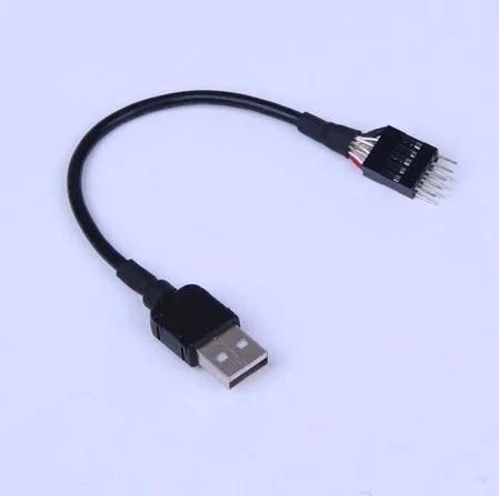 0 has been bifurcated.
At the same time you MUST understand the different versions as this will give you an insight into not just their speeds, but also help you understand the different types of headers.
There are essentially 8 USB versions/names that you may come across. They are summarized in the table below.
| USB Version | Release Year |
Transfer Speed (Gbps) |
Interface Options |
Remarks | Transfer Mode |
|---|---|---|---|---|---|
| USB 2.0 | 2000 | 0.48 | Type A | — Introduced 0.48 Gbps Speeds | High Speed |
| USB 3.0 | 2008 | 5.0 | Type A | — Introduced 5.0 Gbps speeds | SuperSpeed |
| USB 3.1 Gen 1 |
2013 | 5.0 | Type A Type C |
— Same as USB 3.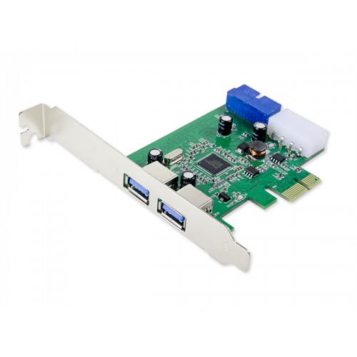 0 0 |
SuperSpeed |
| USB 3.1 Gen 2 |
2013 | 10.0 | Type A Type C |
— Introduced 10.0 Gbps speeds | SuperSpeed+ |
| USB 3.2 Gen 1×1 |
2017 | 5.0 | Type A Type C |
— Same as USB 3.0 | SuperSpeed |
| USB 3.2 Gen 1×2 |
2017 | 10.0 | Type C | — Dual Channel | SuperSpeed |
| USB 3.2 Gen 2×1 |
2017 | 10.0 | Type A Type C |
-Same as USB 3.1 Gen 2 | SuperSpeed+ |
| USB 3.2 Gen 2×2 |
2017 | 20.0 | Type C | — Dual Channel — Introduced 20.0 Gbps speeds |
SuperSpeed++ |
You can see how confusing the names for the USB can be.
Key points to note here are as follows:
- USB 3.0, 3.1 Gen 1 and USB 3.2 Gen 1 are all the SAME, just different names revised over and over with different versions.
 They all use the specifications called SuperSpeed.
 - Often when we talk about USB 3.1 speeds, we are actually referring to USB 3.1 Gen 2 speeds (10 Gbps) NOT Gen 1 since USB 3.1 Gen 1 is the same as USB 3.0 (5.0 Gbps).
- USB 3.2 Gen 2 has the same specifications as the USB 3.1 Gen 2 which is called SuperSpeed+.
- The only new specifications USB 3.2 introduces are dual channels usable only over Type C ports. They double the transfer rate of the older specifications. It is thus named as USB 3.2 Gen 2×2 (indicating dual channel). This specification is called SuperSpeed++ and can reach 20 Mbps.
- USB 3.2 Gen 1×2 uses the specifications of Gen 3.0 (aka SuperSpeed) and doubles it over two channels (i.e 5.0 x 2 = 10 Gbps).
- USB 3.2 Gen 2×2 uses the specifications of USB 3.2 Gen 2 (SuperpSpeed+) and doubles it (i.e 10 x 2 = 20 Gbps) and thus conveniently calling itself SuperSpeed++.
If you are confused on the first glance, its ok. Even the most adept PC builders often do.
The only important USB versions you need to take note of are as follows as they brought a change in speed.
- USB 2.0 = ~0.5 Gbps
- USB 3.0 = 5.0 Gbps (aka USB 3.1 Gen 1, USB 3.2 Gen 2) – SuperSpeed
- USB 3.1 Gen 2 = 10.0 Gbps (aka USB 3.2 Gen 2) – SuperSpeed+
- USB 3.2 Gen 2×2 = 20.0 Gbps – SuperSpeed++
Hopefully, with the USB 4.0 around the corner, the naming convention will get a bit simpler.
With that out of the way, let us now look at what are USB headers.
What are USB Headers?
USB headers are basically connectors on the motherboards for connecting the USB ports found on the PC Case.
If your PC case has USB ports, then it will also come with plugs that need to be connected to the correct headers.
USB Ports as Found on NZXT H710i. This case has 2 x USB 3.2 Gen 1 (Type A) ports – which are same as USB 3.0 essentially. And 1 x USB 3.2 Gen 2 (Type C) port – which is the same as USB 3.1 gen 2.
Different USB versions have different USB headers on the motherboard. In other words, a USB 2.0 header is different from a USB 3.0 header.
The following section explain this.
Type of USB Headers
There are essentially four types of USB headers:
- USB 2.0 Header
- USB 3.0 Header
- USB 3.1 Gen 2 Header
- USB 3.2 Gen 2×2 Header
Therefore, depending upon what USB ports you have on your PC case, you will connect them to the corresponding header.
So USB 2.0 ports will go into the USB 2.0 header, USB 3.0 ports will go into USB 3.0 headers and so on.
1. USB 2.0 Header
These are the simplest to follow.
USB 2.0 Headers
They are small and their pins are arranged in a 5×2 grid. USB 2.0 headers have 9 pins.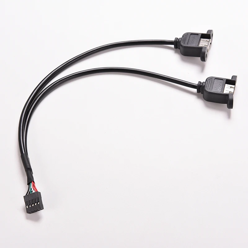 The 10th missing pin from the array serves as the key for aligning the plug correctly.
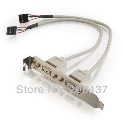
If you have a PC case with USB 2.0 ports, it will be accompanied with this plug:
USB 2.0 Header Cable
2. USB 3.0 Header –
aka USB 3.1 Gen 1, USB 3.2 Gen 1 Header
USB 3.0 Header
A USB 3.0 header has 19 pins arranged in a 2 x 10 array.
This header has been called by many different names including
- USB 3.0
- USB 3.1
- USB 3.1 Gen 1
- USB 3.2 Gen 1
Basically the name that you find for this header on a motherboard specsheet depends upon WHEN the motherboard was manufactured.
The latest motherboards label this header as USB 3.2 Gen 1 header. The older motherboards may have the other names.
So basically as the USB standard changes the nomenclature, so do the motherboard manufacturers.
But essentially, they are ALL THE SAME.
If you have a PC case with USB 3.0 / 3.1 Gen 1 / 3.2 Gen 2 ports, then it will come with a cable similar to the one shown below:
USB 3.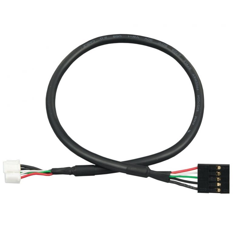 0 Header Cable
3. USB 3.1 Gen 2 Header –
aka USB 3.2 Gen 2 Header
A USB 3.1 Gen 2 header has a very unique form factor. It does not have pins sticking out like the rest of the USB headers.
USB 3.1 Gen 2 HeaderSource: ASUS
In the recent motherboards, this is known as the USB 3.2 Gen 2 header.
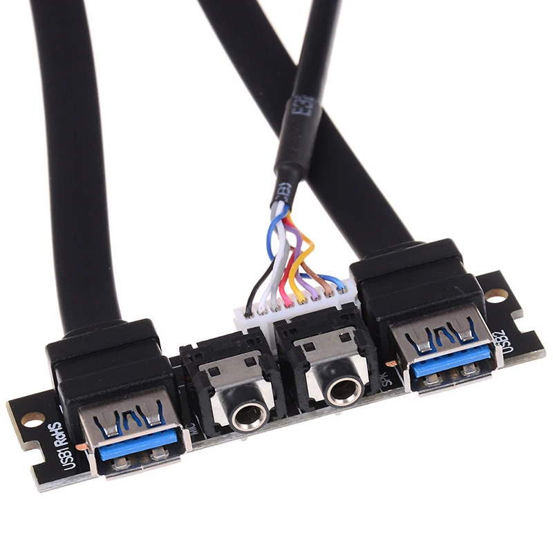
If you have a PC case with a relevant port, then it will come with the following cable.
USB 3.1 Gen 2 header cable
4. USB 3.2 Gen 2×2 Header
These are similar to the USB 3.1 Gen 2 headers above. However, they have dual channels are specifically labelled as USB 3.2 Gen 2×2 on the specifications.
These are quite rare and only a select few top of the line motherboards feature this at the moment.
USB 3.2 Gen 2 x 2 Header as found on ASUS ROG Crosshair VIII Extreme. Note the label reads 2×2 indicating dual channels and support for upto 20 Gbps transfer speed.
How To Locate USB Headers?
USB headers are often located at the bottom or the right edge of your motherboard.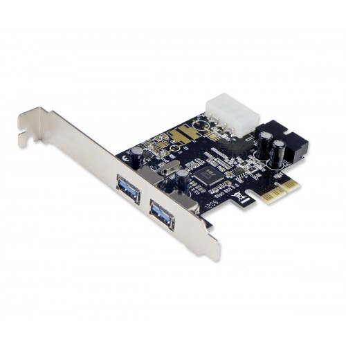
But essentially, there are two ways to locate the USB headers exactly.
- Physical Inspection
- Through the Manual
1. Physical Inspection
If you can find your way across the motherboard, then USB headers aren’t too difficult to spot.
They are often labelled and may also indicate what version they belong to.
USB 2.0 Headers labelled
Here you can see that my motherboard has two USB 2.0 headers. They are labelled as F_USB2 and F_USB1. I can tell by the pin count and the size of the header that it belongs to USB 2.0.
2. Through the Manual
Another easy way to figure out where your USB headers are located is to refer to your motherboard’s layout in the manual.
USB Header location on Gigabyte GA-P67A-UD3
Also Read:
- What are Front Panel Connectors?
- How to Connect Motherboard Internal Speaker?
- Difference Between System Fan and CPU Fan?
FAQ
Can You Use a USB 3.
 0 Case Port with a 3.2 Motherboard Header?
If the motherboard header is a 19 pin connector then yes, you can.
USB 3.0, USB 3.1 Gen 1 and USB 3.2 Gen 1 ports are all the same. They use the same header and connector and have the same transfer speed of 5.0 Gbps.
However, if you have a USB 3.1 Gen 2 port (aka USB 3.2 Gen 2 port), then you will need to buy an adapter to connect your 3.0 case ports.
USB 3.1 Gen 2 to USB 3.0 adapter. These can be troublesome as for some they do not work, for others they only power up a single USB 3.0 port.
USB Ports on the Back I/O Panel DO NOT Connect to USB Headers
Motherboard’s Back I/O Panel also feature a plethora of USB ports. They do not have to be connected to the USB headers.
Motherboards also have a USB ports on the back I/O panel. These do not connect to the USB headers.
USB Ports on the Case are NOT the Same as USB Expansion Cards
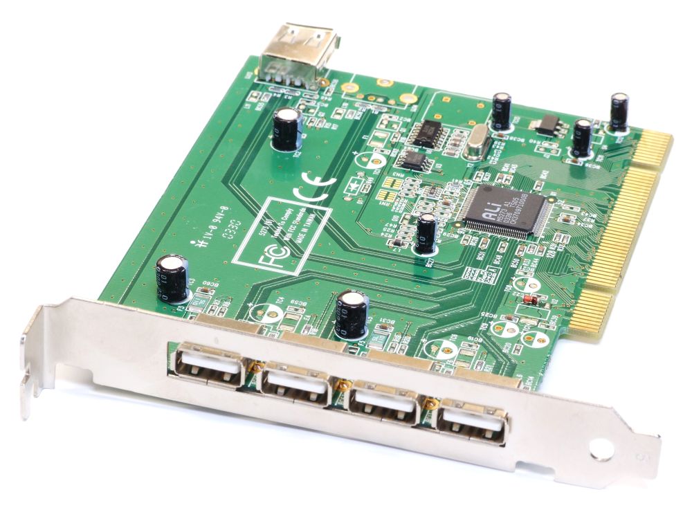
A USB expansion card fits into the PCIe slot. As such they interface with your PC via the PCIe lanes directly and hence DO NOT require to be connected to USB headers.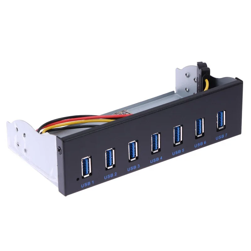
A USB 3.2 Gen 2×2 expansion card connects to PCIe slot.
How Many USB Ports a USB Header Can Support?
Generally, USB headers can support 2 USB ports per header, but that also depends upon the type of header it is.
- USB 2.0 Header – Supports 2 USB ports
- USB 3.0 Header now called USB 3.2 Gen 1 Header – Supports 2 USB ports
- USB 3.1 Gen 2 Header now called USB 3.2 Gen 2 Header – supports one port (Usually Type C)
- USB 3.2 Gen 2×2 Header – supports one port (Type C only)
Is USB 3.2 Gen 2 the Same as Thunderbolt 3?
No, they are not. Thunderbolt 3 ports have a completely different header.
Additionally, Thunderbolt 3 is much faster at 40 Gbps transfer speed! To put that into perspective, USB 3.2 Gen 2 reaches 10 Gbps and dual channel USB 3.2 Gen 2×2 reaches 20 Gbps transfer speed.
Hence Thunderbolt 3.0 is twice as fast as the dual channel USB 3.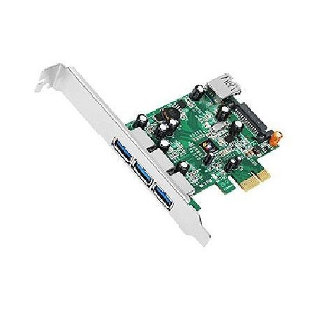 2 Gen 2×2.
Also Read: Why RAM is Called Volatile Memory?
What Are USB Headers & How Do You Get More?
Ever asked yourself, “What are USB headers?”
If so, this is the article for you, especially if you’re seeing the term for the first time and want a quick idea of what USB headers are, how to identify them, and even how to get more of them when needed.
No need to waste time: let’s dive right in!
What are USB Headers?
USB headers refer to dedicated USB connectors on your motherboard that are used for USB ports on your PC case, usually front panel USB ports.
Essentially, they are the end-point for connecting your external (Chassis) USB ports to the motherboard inside your PC through an extension cable.
Internal USB Headers on your Motherboard don’t have the same connectors as your external USB Connectors.
Your motherboard’s USB Headers will look something like the below, and the headers may be labeled as “FPANEL USB”, “F_USB”, “USB30”, “JUSB1” or similar.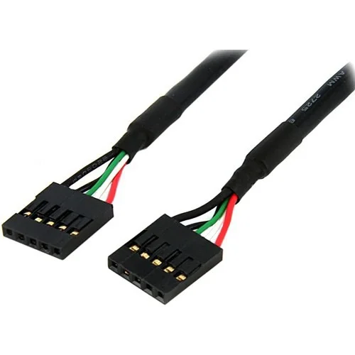 The “F” stands for “Front” and refers to your PC Case’s front access panel, while a “J” may indicate “Jumper,” which refers to the pins on your motherboard that can be shorted to close a circuit (like jump-starting a car).
Image Source: Wikimedia
However they may be labeled, though, there are three basic types of internal USB headers:
- USB 2.0 Headers
- USB 3.2 Gen 1 Headers (Formerly also known as USB 3.0)
- USB 3.2 Gen 2 Headers (Formerly also known as USB 3.1)
Each header type corresponds to the USB version & generation being used, though USB 3.2 Gen 2 Headers are used specifically for USB Type-C connections on your chassis.
USB 2.0 and USB 3.2 Gen 1 (USB 3.0) Headers look the most similar of the three, having a similar pin-based design.
USB 2.0 Headers are usually located at the bottom side of your Motherboard:
While USB 3.2 Gen 1 (USB 3.0) Headers are often either placed at the bottom as well or at the right side of your Motherboard:
USB 3.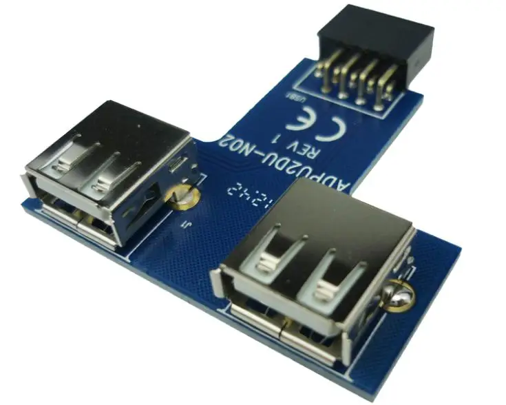 2 Gen 2 Headers don’t have visible pins but are more similar to USB Type-A in appearance. This is also called a USB Type-E Header, pictured below.
They are mostly located on the right side of your Motherboard, right next to the ATX Power Connector:
So, these are the basic USB Headers you can expect to see on your motherboard.
But maybe your case has Type-C support, and your motherboard doesn’t, or you have more USB ports but nowhere to plug in the Header cable.
How do you get more USB Headers?
How Do You Get More USB Headers?
Method 1: DIY USB 2.0 Header Duplication
For USB 2.0 Headers specifically, it turns out you can very easily turn a single header on your motherboard into a port for 2 cables.
USB 2.0 headers support this functionality without a problem, but you need to do a small amount of manual wiring to make it happen.
First, you need to use a pair of tweezers or a similar precision instrument to flip up the plastic tabs at the edges of your second USB header cable.
You’ll basically be extracting the wires/pins from your second cable before placing them inside the ones for your first, directly beside the matching colors. This uses the otherwise-empty pins on the USB 2.0 header and allows both devices to work seamlessly.
Check this YouTube Short from Adamant IT that showcases this process.
Unfortunately, this duplication method only works for USB 2.0 Headers! For more USB 3.0 Headers or more USB Type-E Headers, you’ll need to buy some separate hardware:
Method 2: PCIe USB Headers or USB 3.0 To Type-E Headers
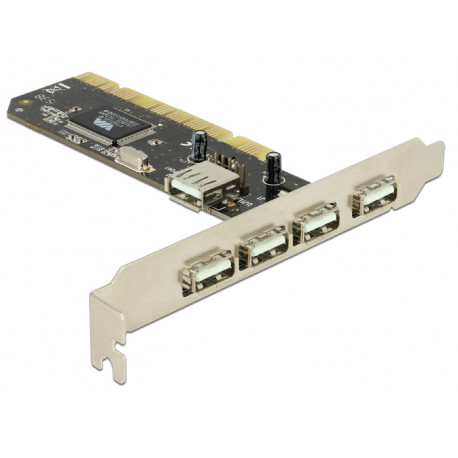
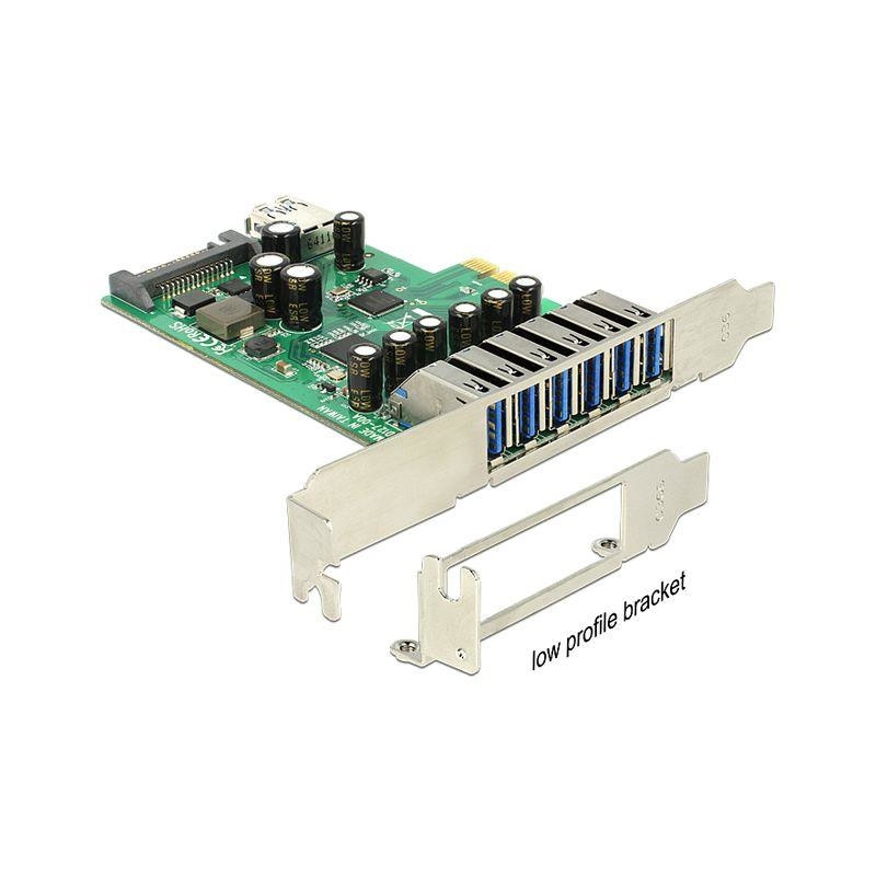
Another way to get more USB headers is to use PCI Express, another ubiquitous feature of modern motherboards (though you get fewer slots as you descend in size).
Source: Delock
Specifically, you’ll be looking for PCI Express expansion cards that come with onboard USB headers for your needs. Whether that’s just more USB 2.0 headers or adding a USB header (like Type-E) that your motherboard doesn’t have, PCI Express should be able to help.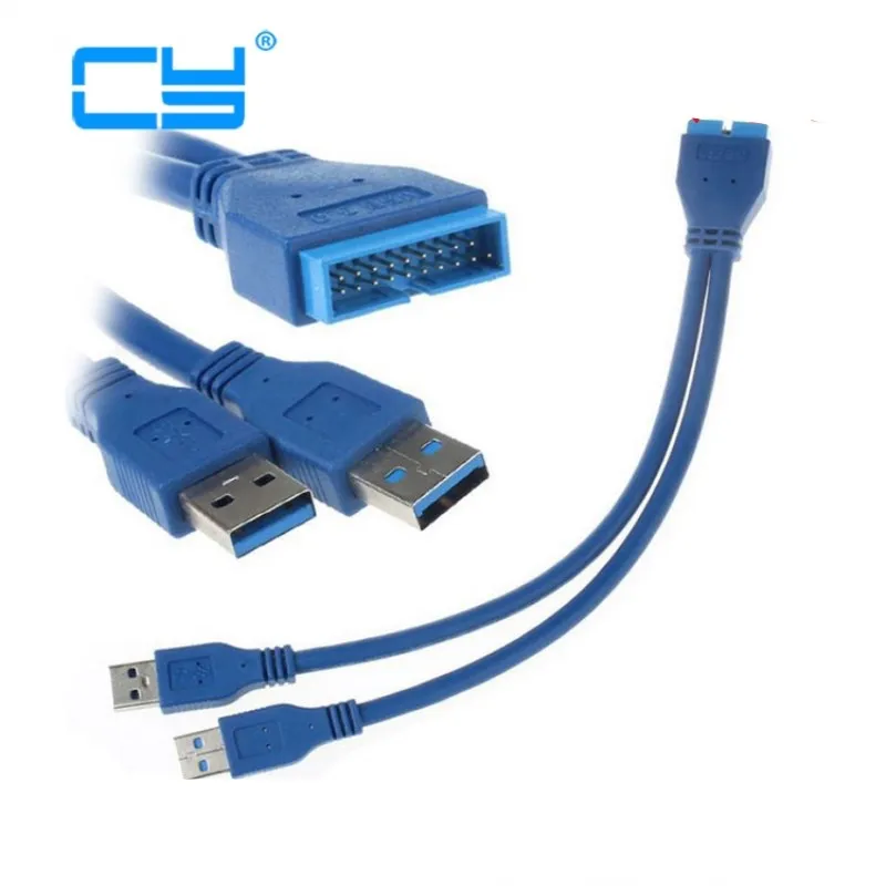
Besides PCI Express cards, you’ll also occasionally come across smaller devices that go right into the ports you’re trying to convert.
There are plentiful USB 3.0 to USB Type-E Headers (for Type-C ports) that just go on top of the original header, for example.
Source: Aliexpress
Before buying niche devices like these, I feel like it’s worth taking the time to talk about their market niche status.
Don’t expect to see PCIe USB Headers from particularly big-name brands, as this is a niche better addressed by smaller tech companies. At least, that seems to be the case judging by the hours of Amazon listing searches I’ve done on these devices.
For my recommendations, I’m going to narrow down the products I found during those long searches to those with a solidly good reputation. Those are as follows:
- Phoenix PCI Express x1 To Dual 20 Pin USB 3.0 Header Card – Takes a standard PCI Express x1 slot and converts it into two 20 Pin USB 3.
 0 Headers.
This is useful when you want more USB 3.0 Type-A ports to be available for use on your chassis. - cablecc PCI Express x4 To USB 3.1 Type-E Card – A PCI Express x4 card with both an internal USB 3.1 Type-E Header (for a Type-C port on the case) and an internal USB 3.0 port. The Header is the show’s star and can add Type-C compatibility to a motherboard that otherwise wouldn’t have it.
- JoyReken USB 3.0 20 Pin Header to USB 3.1 Type-E Adapter – Allows Type-C headers to be used with regular USB 3.0 ports. Isn’t a PCI Express card, and instead is a small attachment placed over the original USB 3.0 Header on the motherboard.
Other Ways To Get More USB Ports
So, besides expanding on your motherboard’s USB headers, what other ways are there to get more USB ports on your PC setup?
USB Hubs
A common and inexpensive solution for many users is just getting a USB hub.
USB hubs take a single USB port and effectively turn it into multiple ports.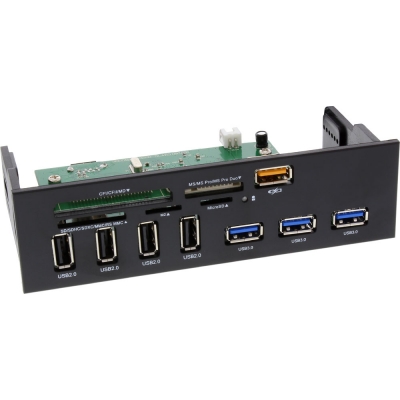 This won’t magically add more bandwidth to that particular port but is fairly useful in the majority of scenarios where you simply need more ports to plug your devices into.
Depending on your needs, you can opt for a powered or unpowered USB hub.
I recommend powered USB hubs for the best results: more on this distinction in the dedicated article.
PCIe USB Expansion Cards
Besides USB hubs, you may also want to take a different route, especially as a desktop user.
Desktop users get the unique boon of access to PCI Express expansions, and this includes PCI Express-based USB Expansion cards.
You can pretty much slap a PCI Express card with additional USB ports into a modern PC without issue, as long as you have a free PCI Express x4 slot.
At the time of writing, my top two recommendations for PCIe USB Expansion are:
- YEELIYA’s PCIe To USB 3.2 Adapter Card – Boasts 2 USB Type-A and 3 USB Type-C ports for under $40.
 Despite USB 3.2 Gen 2 at 20 Gigabits being an advertised feature, is not capable of full 20 Gigabit bandwidth off of a single port, only combined ports. So this is really more of a 3.1/3.2 Gen 1, as are most USB PCIe cards.
20 Gigabits per port is a USB 3.2 Gen 2×2 thing and doesn’t seem to be supported by PCIe cards yet. - FebSmart’s Powered PCIe To USB 3.2 Adapter Card – Boasts 3 USB Type-A and 2 USB Type-C ports for just under $50. Besides solid USB 3.2 speeds for each port (up to 10 Gigabits per port, same as the above card), this card also has great power delivery, making it appropriate for fast-charging and very high-power USB devices, like VR headsets.
Over to You
And that’s all, at least for now! I hope this article answers any questions you might have had about USB Headers, including how to get more of them or how to get around not having enough of them.
Feel free to sound off in the comments below if you have any more questions, especially about USB headers or PC hardware in general.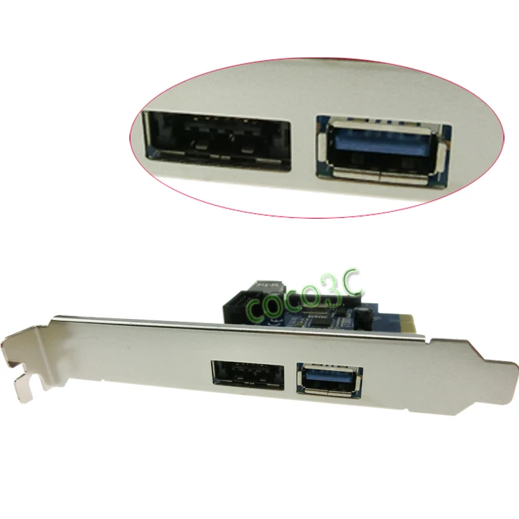 You can also head to the CGDirector Forums to interact with the rest of the CGD Team and Community!
Until then or until next time, have a good one! And remember: every USB 2.0 header on your motherboard is 2 headers if you’re willing to do a little DIY.
CGDirector is Reader-supported. When you buy through our links, we may earn an affiliate commission.
Views of internal and external connectors in PC and laptop
A computer port is an interface or connection point between a computer and its peripherals.
Some of the common peripherals are mouse, keyboard, monitor or display, printer,
speaker, flash drive and others. The main function of a computer port is to act as a connection point,
where you can connect a cable from a peripheral device and provide data transfer from and to the device.
A computer port is also called a communication port because it is responsible for communication between a computer and its peripherals.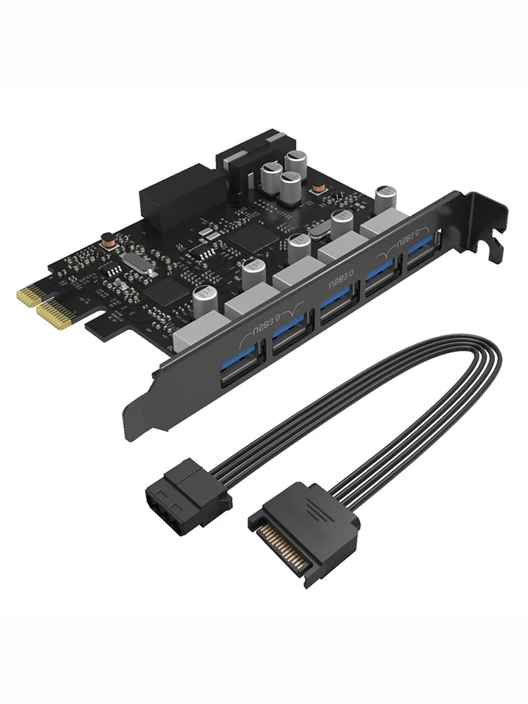
device.
Usually, the female end of the connector is called a port, and it is usually found on the motherboard.
In computers, communication ports can be divided into two types depending on the type or protocol used for communication.
These are serial ports and parallel ports.
The serial port is an interface through which peripheral devices can be connected using
serial protocol, which involves the transfer of data one bit at a time over a single communication line.
The most common type of serial port is the D-Subminiature or D-sub connector, which transmits
RS-232 signals.
On the other hand, a parallel port is an interface through which communication between a computer and its peripheral
the device is carried out in parallel,
that is, data is transmitted or output in parallel using more than one communication line or wire.
A printer port is an example of a parallel port. This article provides a brief introduction to the various types of ports and their
applications.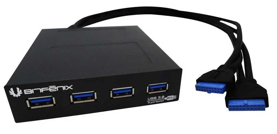
Navigation
PS/2
The PS/2 connector is designed by IBM to connect a mouse and keyboard. It was introduced in a series of IBM computers
Personal Systems/2, hence the name of the PS/2 connector.
PS/2 connectors are magenta for the keyboard and green for the mouse.
PS/2 is a 6-pin DIN connector. The pinout of the PS/2 female connector is shown below.
Even though the PS/2 port pinouts for mouse and keyboard are the same, computers do not recognize
device when connected to the wrong port.
The PS/2 port is now considered a legacy port as the USB port replaced it and very few modern
motherboards include it as a legacy port.
Serial port
Serial port
Although communication in PS/2 and USB is serial, technically the term «serial port» is used for
designation of the interface corresponding to the RS-232 standard. There are two types of serial ports that are commonly used
found on the computer: DB-25 and DE-9.
DB-25
DB-25 is a variant of the D-sub connector and the original port for RS-232 serial communication. They were developed
how
primary port for RS-232 serial communications, but not required for most applications
all
contacts.
Consequently, the DE-9 was designed for serial communications based on RS-232, while the DB-25 was rarely
used
as a serial port and often used as a printer parallel port as a replacement
36 pin
parallel Centronics connector.
DE-9 or RS-232 or COM port
DE-9 is the main port for RS-232 serial communication. This is a D-sub connector with an E shell, which is often
erroneously
called DB-9. The DE-9 port is also called a COM port and provides full duplex serial communication between
computer and its peripherals.
Some of the DE-9 port applications are serial interface with mouse, keyboard, modem, sources
uninterruptible power supply (UPS) and other external devices compatible with RS-232.
The pinout for the DE-9 port is shown below.
The use of DB-25 and DE-9 ports for communication is being reduced and replaced by USB or other ports.
Parallel port or Centronics 36-pin port
connection. The Centronics port is a 36-pin port that was designed as an interface for printers and scanners,
that’s why
the parallel port is also called a Centronics port.
Prior to the widespread use of USB ports, parallel ports were very common in printers. Later port of Centronics
was
replaced by DB-25 port with parallel interface.
Audio ports
Audio ports are used to connect speakers or other audio output devices to the computer. Audio signals may
be analog or digital, and depending on this, the port and its corresponding connector differ.
Surround or 3.5 mm TRS jack
This is the most common audio port and can be used to connect stereo headphones or
channels
surround sound.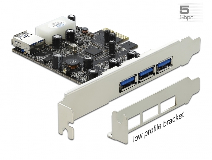 A 6-socket system is included with most computers for audio output as well as for
connections
microphone. 6 connectors are color-coded: blue, light green, pink, orange, black and gray. These 6
connectors
can be used to configure surround sound up to 8 channels.
S/PDIF/TOSLINK
Sony/Phillips Digital Interface Format (S/PDIF) is an audio link used in home media. He
supports
digital audio and can be transmitted using an RCA coaxial audio cable or a TOSLINK fiber optic connector.
Most computer home entertainment systems are equipped with S/PDIF via TOSLINK. TOSLINK (Toshiba Link) —
this is
the most commonly used digital audio port, which can support 7.1 channel surround sound with
Total
one cable.
Video ports
VGA port
The VGA port is used in many computers, projectors, video cards and HDTVs. This is a connector
D sub,
consisting of 15 contacts in 3 rows. The connector is called DE-15. The VGA port is the main interface between
computers and
older CRT monitors. Even modern LCD monitors and LED monitors support VGA ports, but
quality
images deteriorate. VGA transmits analog video signals up to 648X480 resolution.
With the increasing use of digital video, VGA ports are gradually being replaced by HDMI and Display ports. Some
laptops
equipped with built-in VGA ports for connecting to external monitors or projectors. VGA port pinout
shown
below.
Digital Video Interface (DVI)
DVI is a high speed digital interface between a display controller such as a computer and a device
display, such as a monitor. It was designed to transmit lossless digital video signals and replace
analog
VGA technology.
There are three types of DVI connectors depending on the transmitted signals: DVI-I, DVI-D and DVI-A. DVI-I is a DVI port
co
built-in analog and digital signals.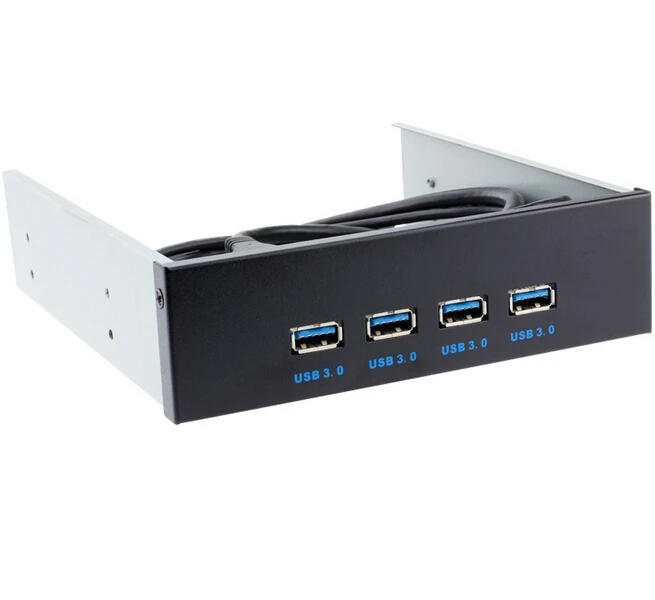 DVI-D only supports digital signals, while DVI-A supports
only
analog signals.
Digital signals can be either single or dual, where a single channel supports a digital signal with
resolution up to 1920X1080, and dual channel supports digital signal up to 2560X1600. On the next
The image compares the DVI-I, DVI-D and DVI-A type structures along with the pinout.
Mini-DVI
The Mini-DVI port is designed by Apple as an alternative to the Mini-VGA port and is physically identical to it. He is smaller
ordinary
port
DVI. This is a 32-pin port capable of transmitting DVI, composite, S-Video, and VGA signals with the appropriate
adapters.
The following image shows a Mini-DVI port and a compatible cable.
Micro-DVI
The Micro-DVI port, as the name suggests, is physically smaller than Mini-DVI and can only carry digital signals.
To
This port can connect external devices with DVI and VGA interfaces, and requires the appropriate
adapters.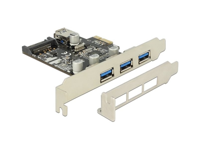
In the following image, the Micro-DVI port can be seen next to the headphone and USB ports.
Display Port
Display Port (DP) is a digital display interface with additional multichannel audio and other forms of data.
Display Port is designed to replace VGA and DVI ports as the primary interface between a computer and
monitor.
The latest DisplayPort 1.3 supports resolutions up to 7680 X 4320.
The display port has a 20-pin connector, which is much smaller than the DVI port and provides better
permission.
The display port pinout is shown below.
RCA connector
The RCA connector can carry composite video and stereo audio signals over three cables. Composite video
transmits analog video signals, and the connector is a yellow RCA connector.
Video signals are transmitted over one channel along with horizontal and vertical synchronization pulses with a maximum
576i (standard definition).
The red and white connectors are used for stereo audio signals (red for the right channel and white for
left
channel).
Component video
Component video is an interface in which video signals are separated into more than two channels, and the quality
video signal
higher than composite video.
Like composite video, component video only carries video signals, and stereo audio must be
two
individual connectors. The component video port can carry both analog and digital video signals.
Commonly seen component video ports use 3 connectors and are color coded green, blue, and
red.
S-Video
The S-Video or Separate Video connector is used to transmit video signals only. Image quality is better than
composite video, but has a lower resolution than component video.
The S-Video port is usually black and is found on all TVs and most computers. S-video port
looks
like a PS/2 port, but consists of only 4 pins.
Of the 4 pins, one pin is used for intensity signals (black and white) and the other pin is
used
for the transmission of color signals. Both of these pins have corresponding ground pins.
HDMI
HDMI is short for High Definition Media Interface. HDMI is a digital interface for connecting devices
high-definition and ultra-high definition, such as computer monitors, high-definition televisions, players
Blu-ray, game consoles, high-definition cameras, etc. HDMI can be used to transfer uncompressed video and
compressed or uncompressed audio signals. The Type A HDMI port is shown below.
HDMI connector consists of 19contacts and the latest HDMI version, i.e. HDMI 2.0 can carry digital video signal from
resolution up to 4096 × 2160 and 32 audio channels. The HDMI port pinout is as follows.
USB
Universal Serial Bus (USB) replaced serial ports, parallel ports, PS/2 connectors,
gaming
ports and chargers for portable devices.
The USB port can be used to transfer data, act as an interface for peripherals, and even
act as a power source for devices connected to it.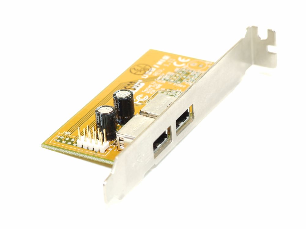 There are three types of USB ports: Type A, Type B, or
mini usb
and Micro USB.
The illustration shows USB connectors of various generations (USB 1.1/2.0/3.0) divided by two types of criteria:
1) connector type
- standard USB connector
- mini USB connector
- micro USB connector
USB Type A
The USB Type-A port is a 4-pin connector. There are different versions of Type A USB ports: USB 1.1, USB
2.0
and
USB 3.0 USB 3.0 is the accepted standard and supports 400Mbps data transfer rates.
USB 3.1 is also released, supporting data transfer rates up to 10Gbps. USB 2.0 is black and USB
3.0
—
blue. The following image shows USB 2.0 and USB 3.0 ports.
The USB Type — A pinout is shown below. The pinout is common to all Type A standards.
USB Type B
USB Type B connectors, officially called Standard-B connectors, are square in shape with a slight rounding or a large square protrusion at the top,
depending on the USB version.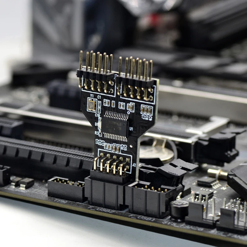 USB Type-B connectors are supported in all versions of USB, including USB 3.0, USB 2.0, and USB 1.1. The second type of connector «B»,
called Powered-B also exists, but only in USB 3.0. USB 3.0 type B connectors are often blue, while USB 2.0 type B and USB 1.1 type
B are often black. This is not always the case because USB Type B connectors and cables can be any color the manufacturer chooses.
USB type B connectors
most commonly found on large computing devices such as printers and scanners. You will also sometimes find USB type B ports on external
storage devices such as optical drives, floppy drives, and hard drive enclosures. USB type B plugs are usually found
on one end of the USB A/B cable. The USB type B plug plugs into the USB type B jack on the printer or other device, and the USB type A plug goes into the
USB type A socket located on the main device such as a computer.
The USB type B connectors in USB 2.0 and USB 1.1 are identical, which means
that a USB type B plug from one version of USB fits into a USB type B socket of both the native version and another version of USB.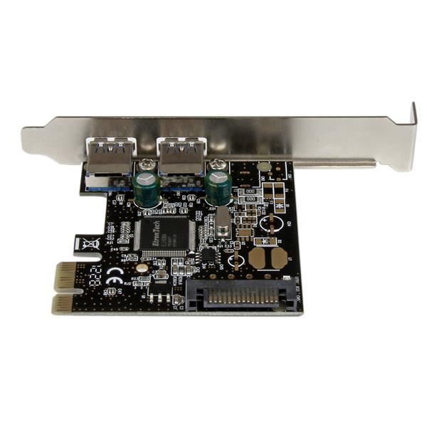 USB 3.0 Type B connectors have
a different shape than the previous ones, so the plugs do not fit the previous sockets. However, the new USB 3.0 Type B form factor was designed in such a way that
to allow previous USB Type B connectors from USB 2.0 and USB 1.1 to fit into USB 3.0 Type B sockets. In other words, USB 1.1 and 2.0 Type B plugs
B are physically compatible with USB 3.0 type B receptacles, but USB 3.0 type B receptacles are not compatible with USB 1.1 or USB 2.0 type B receptacles. Reason for change
is that USB 3.0 Type B connectors have nine pins, which is slightly more than the four pins found in previous connectors
USB Type B to enable faster USB 3.0 data transfer rates. These pins had to be passed somewhere, so the type B shape had to be
change a few.
The above picture shows a USB 3.0 Type micro B connector
USB Type C
USB Type-C is the latest USB specification and is a reversible connector. USB Type-C must
replace
types A and B and is considered promising in the future.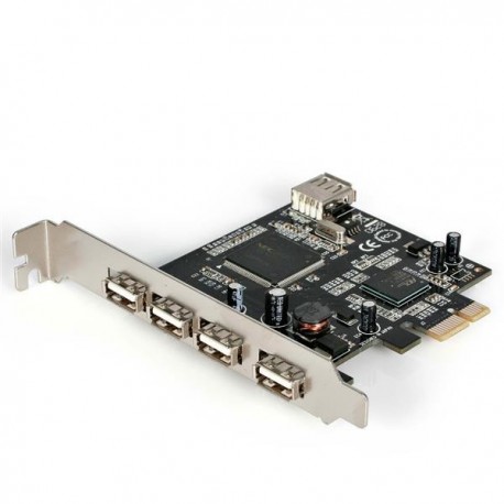
The USB Type-C port has 24 pins. The USB Type-C pinout is shown below. USB Type-C can handle current
3A.
This high current processing function is used in the latest fast charging technology, in which the battery
smartphone
fully charged in a very short time.
RJ-45
Ethernet is a network technology that is used to connect your computer to the Internet and communicate with
others
computers or network devices.
The interface that is used for computer networking and telecommunications is known as the Registered Jack (RJ) and the port
RJ-45, in particular, is used for Ethernet over cable. The RJ-45 connector is an 8 — 8 type modular connector
contacts (8P — 8C).
The latest Ethernet technology is called Gigabit Ethernet and supports data transfer rates of over 10Gbps.
Below
An 8P to 8C type Ethernet or LAN port is shown along with an RJ-45 cable and plug.
The 8P — 8C keyless modular jack is usually referred to as Ethernet RJ-45.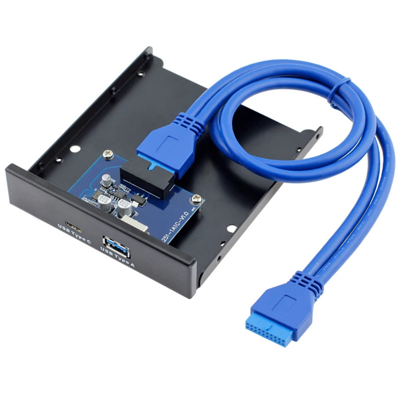 Often RJ-45 ports are equipped with two
LEDs
for transmission indication and packet detection.
RJ-11
RJ-11 is another type of registered connector that is used as an interface to connect
phone, modem or ADSL. Although computers are almost never equipped with an RJ-11 port, they are
main
interface in all telecommunications networks.
RJ-45 and RJ11 ports are similar, but RJ-11 is a smaller port that uses a 6-pin
4-pin connector (6P-4C), although 6-pin-2 pin (6P-2C) is sufficient. Below is a picture of RJ-11 port
and
compatible connector.
The following image can be used to compare RJ-45 and RJ-11 ports.
e-SATA
e-SATA is an external Serial AT Attachment that is used as an interface to connect external
storage devices. Modern e-SATA connectors are called e-SATAp and stand for Power e-SATA ports.
These are hybrid ports capable of supporting both e-SATA and USB. Neither SATA organization nor USB organization
not officially
approved e-SATAp port and should be used at the user’s risk.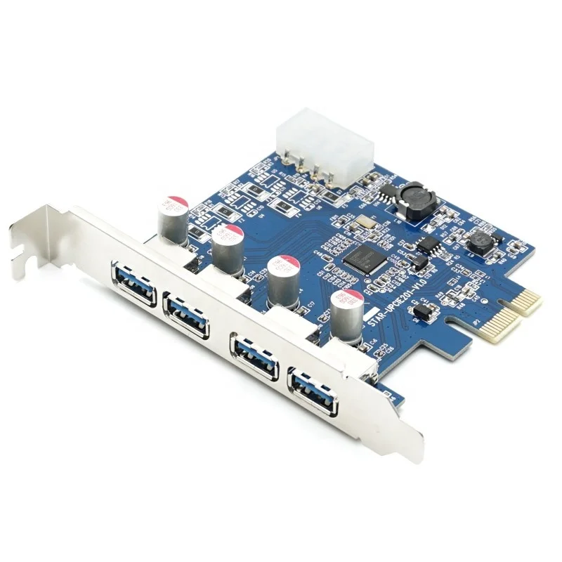
The image above shows the e-SATAp port. It shows that both e-SATA and USB devices can be connected.
Views of internal and external connectors in PC and laptop
A computer port is an interface or connection point between a computer and its peripherals.
Some of the common peripherals are mouse, keyboard, monitor or display, printer,
speaker, flash drive and others. The main function of a computer port is to act as a connection point,
where you can connect a cable from a peripheral device and provide data transfer from and to the device.
A computer port is also called a communication port because it is responsible for communication between a computer and its peripherals.
device.
Usually, the female end of the connector is called a port, and it is usually found on the motherboard.
In computers, communication ports can be divided into two types depending on the type or protocol used for communication.
These are serial ports and parallel ports.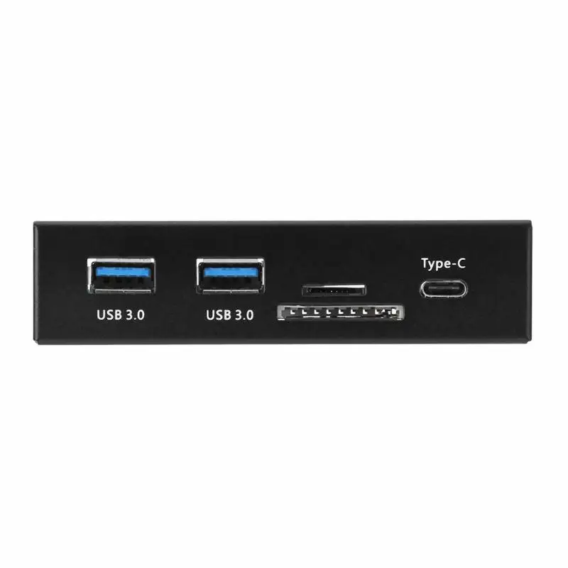
The serial port is an interface through which peripheral devices can be connected using
serial protocol, which involves the transfer of data one bit at a time over a single communication line.
The most common type of serial port is the D-Subminiature or D-sub connector, which transmits
RS-232 signals.
On the other hand, a parallel port is an interface through which communication between a computer and its peripheral
the device is carried out in parallel,
that is, data is transmitted or output in parallel using more than one communication line or wire.
A printer port is an example of a parallel port. This article provides a brief introduction to the various types of ports and their
applications.
Navigation
PS/2
The PS/2 connector is designed by IBM to connect a mouse and keyboard. It was introduced in a series of IBM computers
Personal Systems/2, hence the name of the PS/2 connector.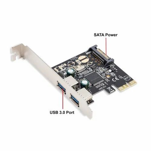
PS/2 connectors are magenta for the keyboard and green for the mouse.
PS/2 is a 6-pin DIN connector. The pinout of the PS/2 female connector is shown below.
Even though the PS/2 port pinouts for mouse and keyboard are the same, computers do not recognize
device when connected to the wrong port.
The PS/2 port is now considered a legacy port as the USB port replaced it and very few modern
motherboards include it as a legacy port.
Serial port
Serial port
Although communication in PS/2 and USB is serial, technically the term «serial port» is used for
designation of the interface corresponding to the RS-232 standard. There are two types of serial ports that are commonly used
found on the computer: DB-25 and DE-9.
DB-25
DB-25 is a variant of the D-sub connector and the original port for RS-232 serial communication. They were developed
how
primary port for RS-232 serial communications, but not required for most applications
all
contacts.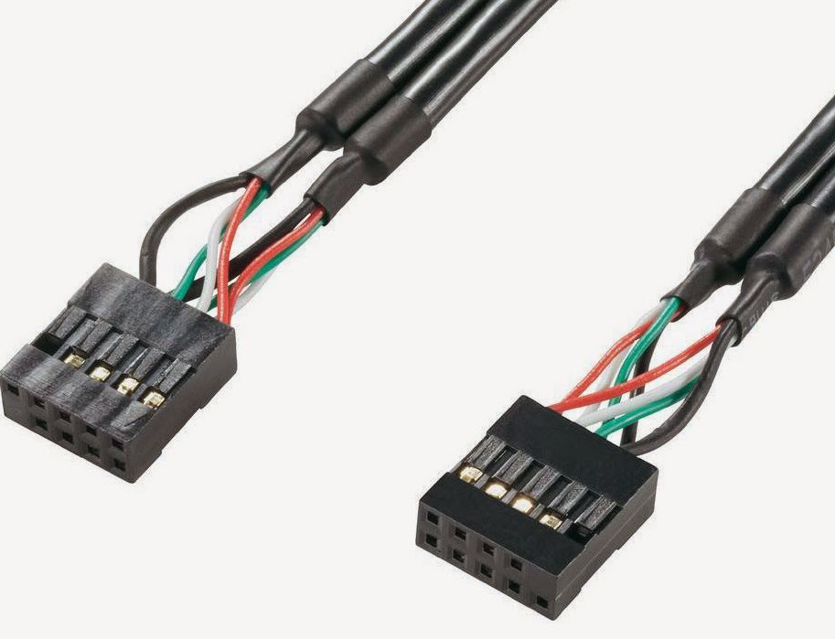
Consequently, the DE-9 was designed for serial communications based on RS-232, while the DB-25 was rarely
used
as a serial port and often used as a printer parallel port as a replacement
36 pin
parallel Centronics connector.
DE-9 or RS-232 or COM port
DE-9 is the main port for RS-232 serial communication. This is a D-sub connector with an E shell, which is often
erroneously
called DB-9. The DE-9 port is also called a COM port and provides full duplex serial communication between
computer and its peripherals.
Some of the DE-9 port applications are serial interface with mouse, keyboard, modem, sources
uninterruptible power supply (UPS) and other external devices compatible with RS-232.
The pinout for the DE-9 port is shown below.
The use of DB-25 and DE-9 ports for communication is being reduced and replaced by USB or other ports.
Parallel port or Centronics 36-pin port
connection. The Centronics port is a 36-pin port that was designed as an interface for printers and scanners,
that’s why
the parallel port is also called a Centronics port.
Prior to the widespread use of USB ports, parallel ports were very common in printers. Later port of Centronics
was
replaced by DB-25 port with parallel interface.
Audio ports
Audio ports are used to connect speakers or other audio output devices to the computer. Audio signals may
be analog or digital, and depending on this, the port and its corresponding connector differ.
Surround or 3.5 mm TRS jack
This is the most common audio port and can be used to connect stereo headphones or
channels
surround sound. A 6-socket system is included with most computers for audio output as well as for
connections
microphone. 6 connectors are color-coded: blue, light green, pink, orange, black and gray.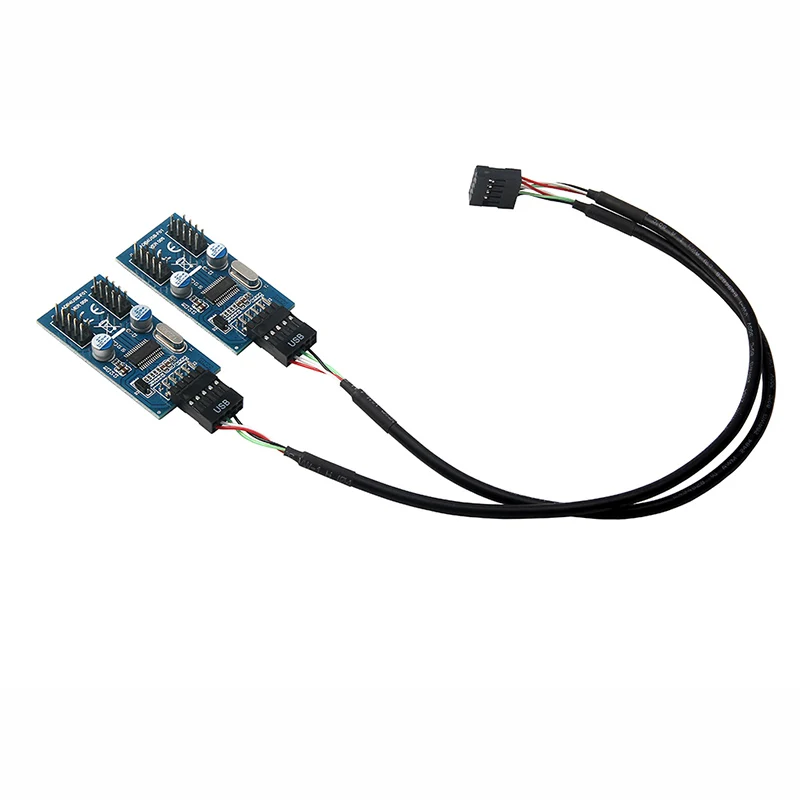 These 6
connectors
can be used to configure surround sound up to 8 channels.
S/PDIF/TOSLINK
Sony/Phillips Digital Interface Format (S/PDIF) is an audio link used in home media. He
supports
digital audio and can be transmitted using an RCA coaxial audio cable or a TOSLINK fiber optic connector.
Most computer home entertainment systems are equipped with S/PDIF via TOSLINK. TOSLINK (Toshiba Link) —
this is
the most commonly used digital audio port, which can support 7.1 channel surround sound with
Total
one cable.
Video ports
VGA port
The VGA port is used in many computers, projectors, video cards and HDTVs. This is a connector
D sub,
consisting of 15 contacts in 3 rows. The connector is called DE-15. The VGA port is the main interface between
computers and
older CRT monitors. Even modern LCD monitors and LED monitors support VGA ports, but
quality
images deteriorate.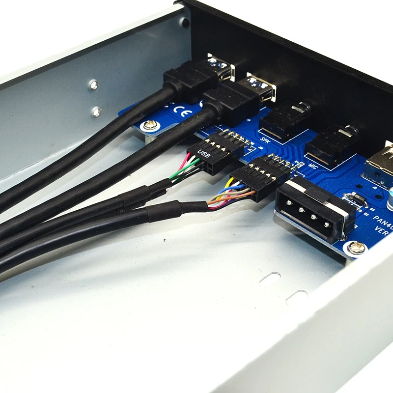 VGA transmits analog video signals up to 648X480 resolution.
With the increasing use of digital video, VGA ports are gradually being replaced by HDMI and Display ports. Some
laptops
equipped with built-in VGA ports for connecting to external monitors or projectors. VGA port pinout
shown
below.
Digital Video Interface (DVI)
DVI is a high speed digital interface between a display controller such as a computer and a device
display, such as a monitor. It was designed to transmit lossless digital video signals and replace
analog
VGA technology.
There are three types of DVI connectors depending on the transmitted signals: DVI-I, DVI-D and DVI-A. DVI-I is a DVI port
co
built-in analog and digital signals. DVI-D only supports digital signals, while DVI-A supports
only
analog signals.
Digital signals can be either single or dual, where a single channel supports a digital signal with
resolution up to 1920X1080, and dual channel supports digital signal up to 2560X1600.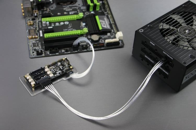 On the next
The image compares the DVI-I, DVI-D and DVI-A type structures along with the pinout.
Mini-DVI
The Mini-DVI port is designed by Apple as an alternative to the Mini-VGA port and is physically identical to it. He is smaller
ordinary
port
DVI. This is a 32-pin port capable of transmitting DVI, composite, S-Video, and VGA signals with the appropriate
adapters.
The following image shows a Mini-DVI port and a compatible cable.
Micro-DVI
The Micro-DVI port, as the name suggests, is physically smaller than Mini-DVI and can only carry digital signals.
To
This port can connect external devices with DVI and VGA interfaces, and requires the appropriate
adapters.
In the following image, the Micro-DVI port can be seen next to the headphone and USB ports.
Display Port
Display Port (DP) is a digital display interface with additional multichannel audio and other forms of data.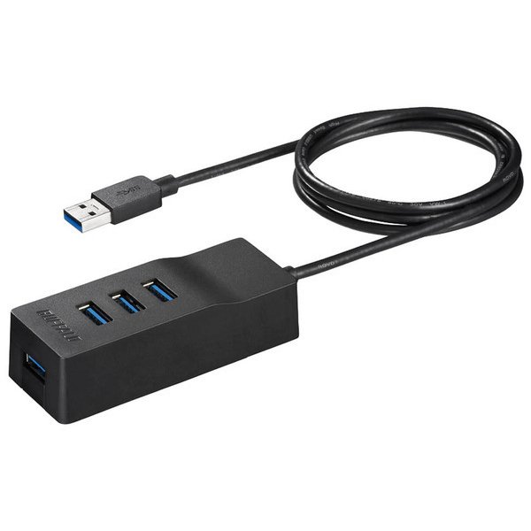
Display Port is designed to replace VGA and DVI ports as the primary interface between a computer and
monitor.
The latest DisplayPort 1.3 supports resolutions up to 7680 X 4320.
The display port has a 20-pin connector, which is much smaller than the DVI port and provides better
permission.
The display port pinout is shown below.
RCA connector
The RCA connector can carry composite video and stereo audio signals over three cables. Composite video
transmits analog video signals, and the connector is a yellow RCA connector.
Video signals are transmitted over one channel along with horizontal and vertical synchronization pulses with a maximum
576i (standard definition).
The red and white connectors are used for stereo audio signals (red for the right channel and white for
left
channel).
Component video
Component video is an interface in which video signals are separated into more than two channels, and the quality
video signal
higher than composite video.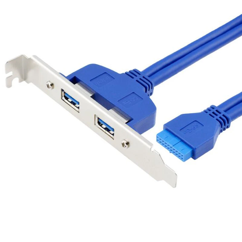
Like composite video, component video only carries video signals, and stereo audio must be
two
individual connectors. The component video port can carry both analog and digital video signals.
Commonly seen component video ports use 3 connectors and are color coded green, blue, and
red.
S-Video
The S-Video or Separate Video connector is used to transmit video signals only. Image quality is better than
composite video, but has a lower resolution than component video.
The S-Video port is usually black and is found on all TVs and most computers. S-video port
looks
like a PS/2 port, but consists of only 4 pins.
Of the 4 pins, one pin is used for intensity signals (black and white) and the other pin is
used
for the transmission of color signals. Both of these pins have corresponding ground pins.
HDMI
HDMI is short for High Definition Media Interface. HDMI is a digital interface for connecting devices
high-definition and ultra-high definition, such as computer monitors, high-definition televisions, players
Blu-ray, game consoles, high-definition cameras, etc.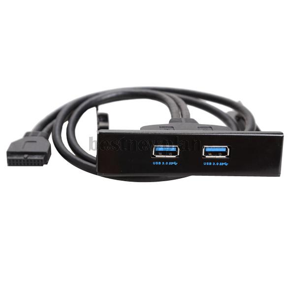 HDMI can be used to transfer uncompressed video and
compressed or uncompressed audio signals. The Type A HDMI port is shown below.
HDMI connector consists of 19contacts and the latest HDMI version, i.e. HDMI 2.0 can carry digital video signal from
resolution up to 4096 × 2160 and 32 audio channels. The HDMI port pinout is as follows.
USB
Universal Serial Bus (USB) replaced serial ports, parallel ports, PS/2 connectors,
gaming
ports and chargers for portable devices.
The USB port can be used to transfer data, act as an interface for peripherals, and even
act as a power source for devices connected to it. There are three types of USB ports: Type A, Type B, or
mini usb
and Micro USB.
The illustration shows USB connectors of various generations (USB 1.1/2.0/3.0) divided by two types of criteria:
1) connector type
- standard USB connector
- mini USB connector
- micro USB connector
USB Type A
The USB Type-A port is a 4-pin connector. There are different versions of Type A USB ports: USB 1.1, USB
2.0
and
USB 3.0 USB 3.0 is the accepted standard and supports 400Mbps data transfer rates.
USB 3.1 is also released, supporting data transfer rates up to 10Gbps. USB 2.0 is black and USB
3.0
—
blue. The following image shows USB 2.0 and USB 3.0 ports.
The USB Type — A pinout is shown below. The pinout is common to all Type A standards.
USB Type B
USB Type B connectors, officially called Standard-B connectors, are square in shape with a slight rounding or a large square protrusion at the top,
depending on the USB version. USB Type-B connectors are supported in all versions of USB, including USB 3.0, USB 2.0, and USB 1.1. The second type of connector «B»,
called Powered-B also exists, but only in USB 3.0. USB 3.0 type B connectors are often blue, while USB 2.0 type B and USB 1.1 type
B are often black. This is not always the case because USB Type B connectors and cables can be any color the manufacturer chooses.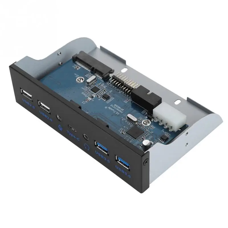
USB type B connectors
most commonly found on large computing devices such as printers and scanners. You will also sometimes find USB type B ports on external
storage devices such as optical drives, floppy drives, and hard drive enclosures. USB type B plugs are usually found
on one end of the USB A/B cable. The USB type B plug plugs into the USB type B jack on the printer or other device, and the USB type A plug goes into the
USB type A socket located on the main device such as a computer.
The USB type B connectors in USB 2.0 and USB 1.1 are identical, which means
that a USB type B plug from one version of USB fits into a USB type B socket of both the native version and another version of USB. USB 3.0 Type B connectors have
a different shape than the previous ones, so the plugs do not fit the previous sockets. However, the new USB 3.0 Type B form factor was designed in such a way that
to allow previous USB Type B connectors from USB 2. 0 and USB 1.1 to fit into USB 3.0 Type B sockets. In other words, USB 1.1 and 2.0 Type B plugs
B are physically compatible with USB 3.0 type B receptacles, but USB 3.0 type B receptacles are not compatible with USB 1.1 or USB 2.0 type B receptacles. Reason for change
is that USB 3.0 Type B connectors have nine pins, which is slightly more than the four pins found in previous connectors
USB Type B to enable faster USB 3.0 data transfer rates. These pins had to be passed somewhere, so the type B shape had to be
change a few.
The above picture shows a USB 3.0 Type micro B connector
USB Type C
USB Type-C is the latest USB specification and is a reversible connector. USB Type-C must
replace
types A and B and is considered promising in the future.
The USB Type-C port has 24 pins. The USB Type-C pinout is shown below. USB Type-C can handle current
3A.
This high current processing function is used in the latest fast charging technology, in which the battery
smartphone
fully charged in a very short time.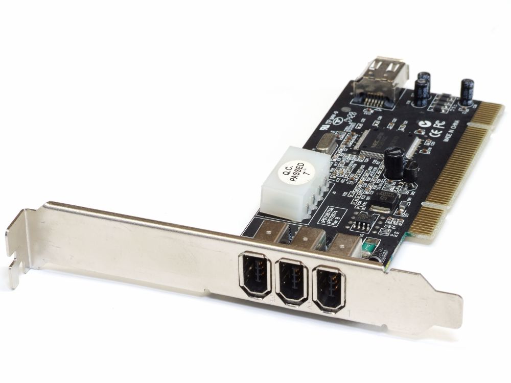
RJ-45
Ethernet is a network technology that is used to connect your computer to the Internet and communicate with
others
computers or network devices.
The interface that is used for computer networking and telecommunications is known as the Registered Jack (RJ) and the port
RJ-45, in particular, is used for Ethernet over cable. The RJ-45 connector is an 8 — 8 type modular connector
contacts (8P — 8C).
The latest Ethernet technology is called Gigabit Ethernet and supports data transfer rates of over 10Gbps.
Below
An 8P to 8C type Ethernet or LAN port is shown along with an RJ-45 cable and plug.
The 8P — 8C keyless modular jack is usually referred to as Ethernet RJ-45. Often RJ-45 ports are equipped with two
LEDs
for transmission indication and packet detection.
RJ-11
RJ-11 is another type of registered connector that is used as an interface to connect
phone, modem or ADSL. Although computers are almost never equipped with an RJ-11 port, they are
main
interface in all telecommunications networks.
RJ-45 and RJ11 ports are similar, but RJ-11 is a smaller port that uses a 6-pin
4-pin connector (6P-4C), although 6-pin-2 pin (6P-2C) is sufficient. Below is a picture of RJ-11 port
and
compatible connector.
The following image can be used to compare RJ-45 and RJ-11 ports.
e-SATA
e-SATA is an external Serial AT Attachment that is used as an interface to connect external
storage devices. Modern e-SATA connectors are called e-SATAp and stand for Power e-SATA ports.
These are hybrid ports capable of supporting both e-SATA and USB. Neither SATA organization nor USB organization
not officially
approved e-SATAp port and should be used at the user’s risk.
The image above shows the e-SATAp port. It shows that both e-SATA and USB devices can be connected.
Views of internal and external connectors in PC and laptop
A computer port is an interface or connection point between a computer and its peripherals.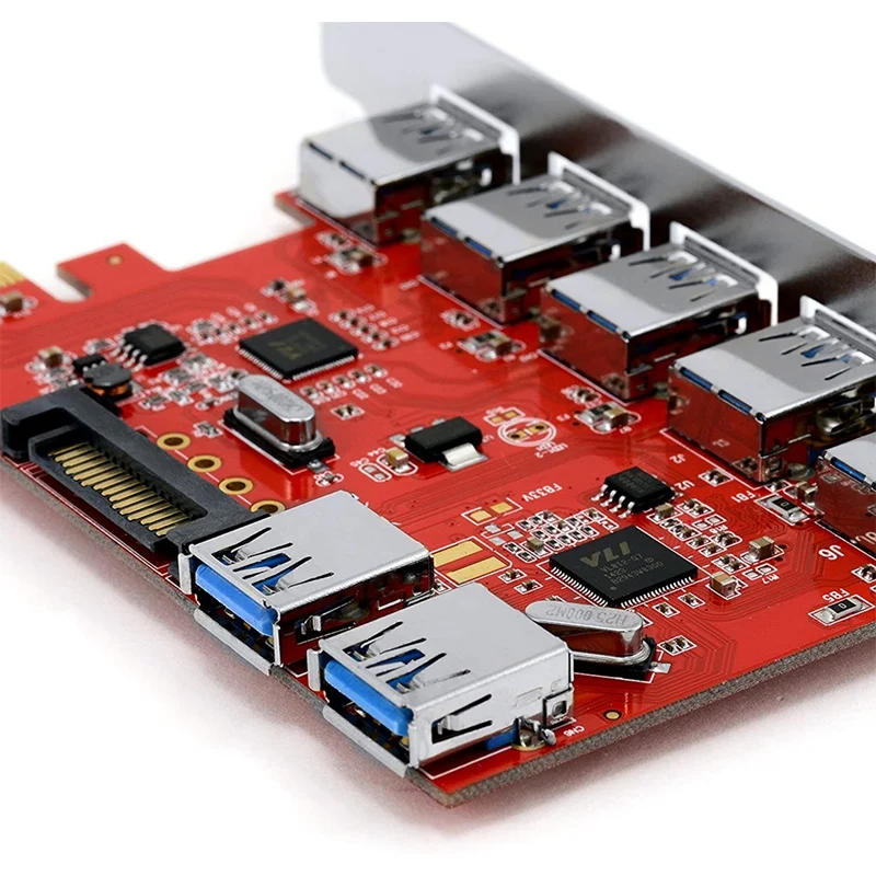
Some of the common peripherals are mouse, keyboard, monitor or display, printer,
speaker, flash drive and others. The main function of a computer port is to act as a connection point,
where you can connect a cable from a peripheral device and provide data transfer from and to the device.
A computer port is also called a communication port because it is responsible for communication between a computer and its peripherals.
device.
Usually, the female end of the connector is called a port, and it is usually found on the motherboard.
In computers, communication ports can be divided into two types depending on the type or protocol used for communication.
These are serial ports and parallel ports.
The serial port is an interface through which peripheral devices can be connected using
serial protocol, which involves the transfer of data one bit at a time over a single communication line.
The most common type of serial port is the D-Subminiature or D-sub connector, which transmits
RS-232 signals.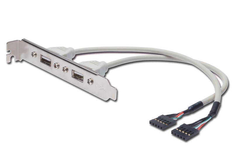
On the other hand, a parallel port is an interface through which communication between a computer and its peripheral
the device is carried out in parallel,
that is, data is transmitted or output in parallel using more than one communication line or wire.
A printer port is an example of a parallel port. This article provides a brief introduction to the various types of ports and their
applications.
Navigation
PS/2
The PS/2 connector is designed by IBM to connect a mouse and keyboard. It was introduced in a series of IBM computers
Personal Systems/2, hence the name of the PS/2 connector.
PS/2 connectors are magenta for the keyboard and green for the mouse.
PS/2 is a 6-pin DIN connector. The pinout of the PS/2 female connector is shown below.
Even though the PS/2 port pinouts for mouse and keyboard are the same, computers do not recognize
device when connected to the wrong port.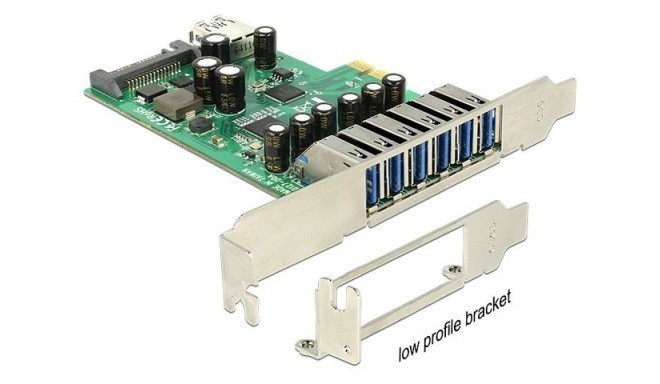
The PS/2 port is now considered a legacy port as the USB port replaced it and very few modern
motherboards include it as a legacy port.
Serial port
Serial port
Although communication in PS/2 and USB is serial, technically the term «serial port» is used for
designation of the interface corresponding to the RS-232 standard. There are two types of serial ports that are commonly used
found on the computer: DB-25 and DE-9.
DB-25
DB-25 is a variant of the D-sub connector and the original port for RS-232 serial communication. They were developed
how
primary port for RS-232 serial communications, but not required for most applications
all
contacts.
Consequently, the DE-9 was designed for serial communications based on RS-232, while the DB-25 was rarely
used
as a serial port and often used as a printer parallel port as a replacement
36 pin
parallel Centronics connector.
DE-9 or RS-232 or COM port
DE-9 is the main port for RS-232 serial communication. This is a D-sub connector with an E shell, which is often
erroneously
called DB-9. The DE-9 port is also called a COM port and provides full duplex serial communication between
computer and its peripherals.
Some of the DE-9 port applications are serial interface with mouse, keyboard, modem, sources
uninterruptible power supply (UPS) and other external devices compatible with RS-232.
The pinout for the DE-9 port is shown below.
The use of DB-25 and DE-9 ports for communication is being reduced and replaced by USB or other ports.
Parallel port or Centronics 36-pin port
connection. The Centronics port is a 36-pin port that was designed as an interface for printers and scanners,
that’s why
the parallel port is also called a Centronics port.
Prior to the widespread use of USB ports, parallel ports were very common in printers. Later port of Centronics
was
replaced by DB-25 port with parallel interface.
Audio ports
Audio ports are used to connect speakers or other audio output devices to the computer. Audio signals may
be analog or digital, and depending on this, the port and its corresponding connector differ.
Surround or 3.5 mm TRS jack
This is the most common audio port and can be used to connect stereo headphones or
channels
surround sound. A 6-socket system is included with most computers for audio output as well as for
connections
microphone. 6 connectors are color-coded: blue, light green, pink, orange, black and gray. These 6
connectors
can be used to configure surround sound up to 8 channels.
S/PDIF/TOSLINK
Sony/Phillips Digital Interface Format (S/PDIF) is an audio link used in home media. He
supports
digital audio and can be transmitted using an RCA coaxial audio cable or a TOSLINK fiber optic connector.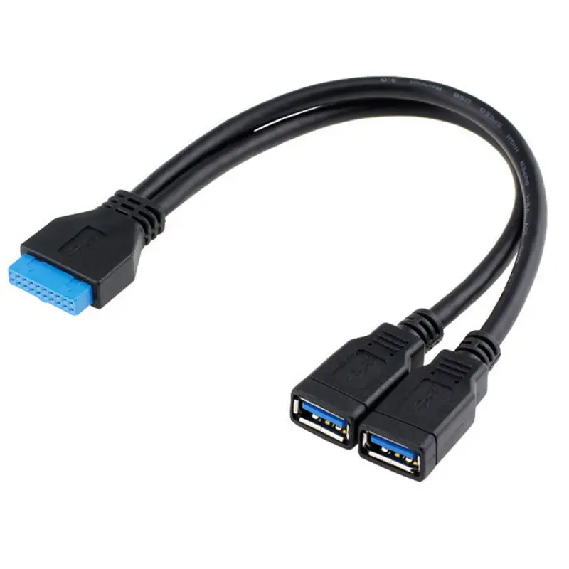
Most computer home entertainment systems are equipped with S/PDIF via TOSLINK. TOSLINK (Toshiba Link) —
this is
the most commonly used digital audio port, which can support 7.1 channel surround sound with
Total
one cable.
Video ports
VGA port
The VGA port is used in many computers, projectors, video cards and HDTVs. This is a connector
D sub,
consisting of 15 contacts in 3 rows. The connector is called DE-15. The VGA port is the main interface between
computers and
older CRT monitors. Even modern LCD monitors and LED monitors support VGA ports, but
quality
images deteriorate. VGA transmits analog video signals up to 648X480 resolution.
With the increasing use of digital video, VGA ports are gradually being replaced by HDMI and Display ports. Some
laptops
equipped with built-in VGA ports for connecting to external monitors or projectors. VGA port pinout
shown
below.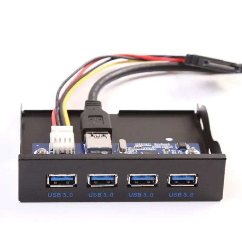
Digital Video Interface (DVI)
DVI is a high speed digital interface between a display controller such as a computer and a device
display, such as a monitor. It was designed to transmit lossless digital video signals and replace
analog
VGA technology.
There are three types of DVI connectors depending on the transmitted signals: DVI-I, DVI-D and DVI-A. DVI-I is a DVI port
co
built-in analog and digital signals. DVI-D only supports digital signals, while DVI-A supports
only
analog signals.
Digital signals can be either single or dual, where a single channel supports a digital signal with
resolution up to 1920X1080, and dual channel supports digital signal up to 2560X1600. On the next
The image compares the DVI-I, DVI-D and DVI-A type structures along with the pinout.
Mini-DVI
The Mini-DVI port is designed by Apple as an alternative to the Mini-VGA port and is physically identical to it. He is smaller
ordinary
port
DVI.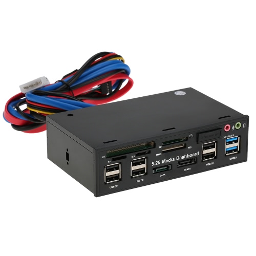 This is a 32-pin port capable of transmitting DVI, composite, S-Video, and VGA signals with the appropriate
adapters.
The following image shows a Mini-DVI port and a compatible cable.
Micro-DVI
The Micro-DVI port, as the name suggests, is physically smaller than Mini-DVI and can only carry digital signals.
To
This port can connect external devices with DVI and VGA interfaces, and requires the appropriate
adapters.
In the following image, the Micro-DVI port can be seen next to the headphone and USB ports.
Display Port
Display Port (DP) is a digital display interface with additional multichannel audio and other forms of data.
Display Port is designed to replace VGA and DVI ports as the primary interface between a computer and
monitor.
The latest DisplayPort 1.3 supports resolutions up to 7680 X 4320.
The display port has a 20-pin connector, which is much smaller than the DVI port and provides better
permission.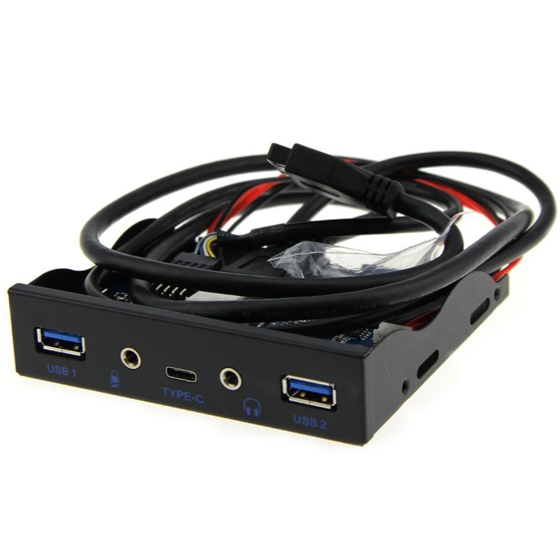
The display port pinout is shown below.
RCA connector
The RCA connector can carry composite video and stereo audio signals over three cables. Composite video
transmits analog video signals, and the connector is a yellow RCA connector.
Video signals are transmitted over one channel along with horizontal and vertical synchronization pulses with a maximum
576i (standard definition).
The red and white connectors are used for stereo audio signals (red for the right channel and white for
left
channel).
Component video
Component video is an interface in which video signals are separated into more than two channels, and the quality
video signal
higher than composite video.
Like composite video, component video only carries video signals, and stereo audio must be
two
individual connectors. The component video port can carry both analog and digital video signals.
Commonly seen component video ports use 3 connectors and are color coded green, blue, and
red.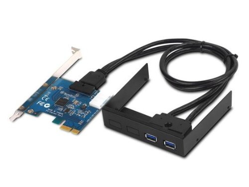
S-Video
The S-Video or Separate Video connector is used to transmit video signals only. Image quality is better than
composite video, but has a lower resolution than component video.
The S-Video port is usually black and is found on all TVs and most computers. S-video port
looks
like a PS/2 port, but consists of only 4 pins.
Of the 4 pins, one pin is used for intensity signals (black and white) and the other pin is
used
for the transmission of color signals. Both of these pins have corresponding ground pins.
HDMI
HDMI is short for High Definition Media Interface. HDMI is a digital interface for connecting devices
high-definition and ultra-high definition, such as computer monitors, high-definition televisions, players
Blu-ray, game consoles, high-definition cameras, etc. HDMI can be used to transfer uncompressed video and
compressed or uncompressed audio signals. The Type A HDMI port is shown below.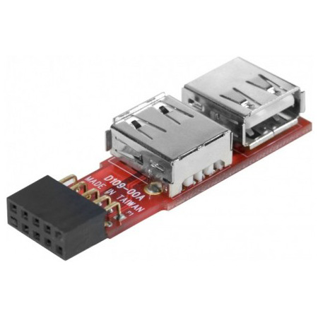
HDMI connector consists of 19contacts and the latest HDMI version, i.e. HDMI 2.0 can carry digital video signal from
resolution up to 4096 × 2160 and 32 audio channels. The HDMI port pinout is as follows.
USB
Universal Serial Bus (USB) replaced serial ports, parallel ports, PS/2 connectors,
gaming
ports and chargers for portable devices.
The USB port can be used to transfer data, act as an interface for peripherals, and even
act as a power source for devices connected to it. There are three types of USB ports: Type A, Type B, or
mini usb
and Micro USB.
The illustration shows USB connectors of various generations (USB 1.1/2.0/3.0) divided by two types of criteria:
1) connector type
- standard USB connector
- mini USB connector
- micro USB connector
USB Type A
The USB Type-A port is a 4-pin connector. There are different versions of Type A USB ports: USB 1.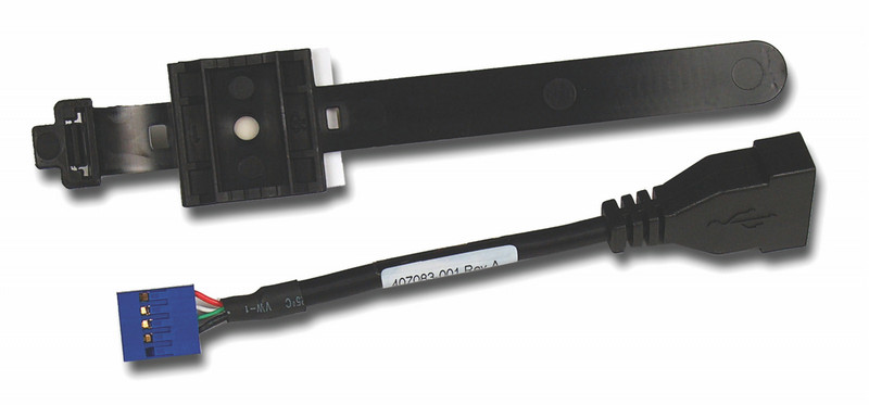 1, USB
2.0
and
USB 3.0 USB 3.0 is the accepted standard and supports 400Mbps data transfer rates.
USB 3.1 is also released, supporting data transfer rates up to 10Gbps. USB 2.0 is black and USB
3.0
—
blue. The following image shows USB 2.0 and USB 3.0 ports.
The USB Type — A pinout is shown below. The pinout is common to all Type A standards.
USB Type B
USB Type B connectors, officially called Standard-B connectors, are square in shape with a slight rounding or a large square protrusion at the top,
depending on the USB version. USB Type-B connectors are supported in all versions of USB, including USB 3.0, USB 2.0, and USB 1.1. The second type of connector «B»,
called Powered-B also exists, but only in USB 3.0. USB 3.0 type B connectors are often blue, while USB 2.0 type B and USB 1.1 type
B are often black. This is not always the case because USB Type B connectors and cables can be any color the manufacturer chooses.
USB type B connectors
most commonly found on large computing devices such as printers and scanners. You will also sometimes find USB type B ports on external
storage devices such as optical drives, floppy drives, and hard drive enclosures. USB type B plugs are usually found
on one end of the USB A/B cable. The USB type B plug plugs into the USB type B jack on the printer or other device, and the USB type A plug goes into the
USB type A socket located on the main device such as a computer.
The USB type B connectors in USB 2.0 and USB 1.1 are identical, which means
that a USB type B plug from one version of USB fits into a USB type B socket of both the native version and another version of USB. USB 3.0 Type B connectors have
a different shape than the previous ones, so the plugs do not fit the previous sockets. However, the new USB 3.0 Type B form factor was designed in such a way that
to allow previous USB Type B connectors from USB 2.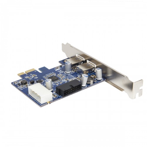 0 and USB 1.1 to fit into USB 3.0 Type B sockets. In other words, USB 1.1 and 2.0 Type B plugs
B are physically compatible with USB 3.0 type B receptacles, but USB 3.0 type B receptacles are not compatible with USB 1.1 or USB 2.0 type B receptacles. Reason for change
is that USB 3.0 Type B connectors have nine pins, which is slightly more than the four pins found in previous connectors
USB Type B to enable faster USB 3.0 data transfer rates. These pins had to be passed somewhere, so the type B shape had to be
change a few.
The above picture shows a USB 3.0 Type micro B connector
USB Type C
USB Type-C is the latest USB specification and is a reversible connector. USB Type-C must
replace
types A and B and is considered promising in the future.
The USB Type-C port has 24 pins. The USB Type-C pinout is shown below. USB Type-C can handle current
3A.
This high current processing function is used in the latest fast charging technology, in which the battery
smartphone
fully charged in a very short time.
RJ-45
Ethernet is a network technology that is used to connect your computer to the Internet and communicate with
others
computers or network devices.
The interface that is used for computer networking and telecommunications is known as the Registered Jack (RJ) and the port
RJ-45, in particular, is used for Ethernet over cable. The RJ-45 connector is an 8 — 8 type modular connector
contacts (8P — 8C).
The latest Ethernet technology is called Gigabit Ethernet and supports data transfer rates of over 10Gbps.
Below
An 8P to 8C type Ethernet or LAN port is shown along with an RJ-45 cable and plug.
The 8P — 8C keyless modular jack is usually referred to as Ethernet RJ-45. Often RJ-45 ports are equipped with two
LEDs
for transmission indication and packet detection.
RJ-11
RJ-11 is another type of registered connector that is used as an interface to connect
phone, modem or ADSL. Although computers are almost never equipped with an RJ-11 port, they are
main
interface in all telecommunications networks.