Motherboard Anatomy: Connections and Components of the PC Motherboard
Introduction to Motherboards
While the motherboard may not be the most exciting part of your PC build, it’s just as essential as any other component. If you don’t have one (or you buy one that’s incompatible with another part) your rig simply won’t work.
This is because everything is connected to the motherboard in some way, shape, or form. Your CPU, storage drives, memory, graphics card, peripherals, and even case are all either directly seated in the motherboard or connected via cable, either directly or indirectly.
Due to its paramount importance, it’s highly beneficial to understand the basic layout and function of the components in a motherboard. Doing so will make you a more competent PC-builder and improve your ability to troubleshoot if things go awry.
Diagram of Motherboard Components and Connectors
Below, we’ve put together a diagram of the most important parts of the motherboard. Motherboard layouts may vary between models (for instance, higher-end boards may have more heatsinks, memory slots, or M.2 slots), however all modern boards tend to have the same general layout, regardless of manufacturer or chipset.
The motherboard shown below is an ASRock B560M-HDV. We chose it due to its lack of heatsinks, which allows for high visibility of all major components.
ASRock B560M-HDV (Credit: ASRock)
The Parts of the Motherboard
Let’s look at the basic function of each component shown above.
Power Connectors
The power supply is connected to the motherboard in two locations via power connectors.
Motherboard Power Connector
The motherboard power connector, also called the ATX Power Connector, is a 24-pin plugin that supplies the entire motherboard with power. It’s typically found on the far right side of the motherboard. PCIe slots, SATA ports, RAM modules, and more are all supplied power from this plugin.
CPU Power Connector
Typically found near the top of the motherboard towards the left side, the CPU power connector (also called the ATX 12V Power Connector) is where the power supply plugs into the motherboard, supplying electricity to the processor.
CPU Socket
The CPU socket, as its name suggests, is the location in which the processor is housed. All major components are connected to the CPU socket, allowing the processor to control and interact with the memory, graphics card, storage drives, and more.
VRMs
VRMs, or Voltage Regulator Modules, are groups of transistors that deliver power to components and regulate it so that they don’t receive too much. The most important VRM is the one that regulates your CPU’s power, which is typically located to the left and above the CPU socket.
VRMs are composed of two types of transistors, called power chokes and capacitors. Power chokes are the square-shaped transistors, and capacitors are the cylindrical ones next to them.
Higher-end motherboards tend to have VRM heatsinks since these modules tend to get pretty hot, especially when overclocking your CPU. If this is the case, your VRMs may not be visible.
It’s unlikely that you’ll ever need to mess with your VRMs, however it’s good to understand them so you can make an informed decision when buying a motherboard. For a more in-depth look at VRMs, we recommend Logical Increments’ article on the topic.
Fan Headers
Most motherboards have three or more fan headers, the connectors into which any CPU or case fans are plugged. These provide power to the fans.
Motherboards will typically have a specific connector labeled as the “CPU Fan” header, which is almost always the one closest to the CPU socket. It’s important to plug your CPU cooler into this one specifically, since some motherboards will perceive that the CPU cooler isn’t plugged in at all if you don’t.
DIMM Slots
DIMM (Dual In-Line Memory Module) slots, often called RAM or memory slots, are the notches in which your RAM is seated. They’re connected to the CPU, allowing fast data transfer between your memory and processor.
Mainstream motherboards come with either two or four DIMM slots.
SATA Ports
Two SATA ports
If you’re using a SATA SSD or HDD, you’ll almost certainly attach these to the motherboard via SATA cable. These cables plug into the motherboard’s SATA ports, allowing the storage drive and CPU to interact.
Motherboards typically come with at least four SATA ports, and often have even more. It’s common for some to be facing upwards and some to be perpendicular to the board, as in the graph above (the side-facing SATA ports are directly below the upwards-facing ones).
M.2 Slots
An M.2 Slot
M.2 slots are ports in the motherboard which are primarily used to connect M.2 storage drives or WiFi/Bluetooth expansion cards.
Most modern motherboards come with at least two of these, and they’re often covered with a heatsink. M.2 slots most commonly use the PCIe protocol to transfer data, but some support SATA as well.
See Also: How to Install an M.2 SSD
If a motherboard supports PCIe gen 4, it will usually have at least one M.2 slot that also supports gen 4. This allows for extremely fast data transfer speeds with a gen 4 SSD.
PCIe Slots
Four PCIe slots on an MSI Z370 motherboard
PCIe slots are used to connect expansion cards to the motherboard. They can come in a variety of sizes; the bigger they are, the more “lanes” they support.
CPUs support only a limited number of PCIe lanes, and the quantity varies between models. A PCIe x16 slot, for example, uses 16 of these lanes, while a PCIe x4 slot uses only four.
Different components use different numbers of lanes. For instance, discrete graphics cards use 16, while PCIe SSDs use four apiece.
Motherboards use different combinations of PCIe slots. For instance, the B560M-HDV shown in the diagram uses only one PCIe x16 and two PCIe x1 slots, in addition to the M.2 slots. Other boards like the Z590 Aorus Xtreme use three PCIe x16 slots.
It’s important to note that smaller cards, such as a PCIe x4 card, can be plugged into larger slots, such as a PCIe x16. PCIe slots typically come in four sizes: x1, x4, x8, and x16.
USB Headers
If you want to plug USB devices directly into your chassis, you’ll need to connect the cables provided with the case into the motherboard’s USB headers.
USB headers nowadays typically come in two varieties: USB 2.0 and USB 3.0. As you could probably guess, USB 3.0 supports a significantly higher data transfer bandwidth: USB 2.0 supports up to 480 Mb/s, while 3.0 can transfer 4800 Mb/s.
HD Audio Header
The HD Audio header is similar to the USB headers, in that it allows you to use peripherals that are plugged directly into your case. In this instance, those peripherals are audio devices like headsets, microphones, or audio interfaces.
System Panel Header
If you want to power on your PC with the power button (which we highly recommend), you’ll need to make use of the system panel header. This is where the rest of your chassis cables are connected, including the ones that control the power switch, power button LEDs, and reset button.
I/O Ports
I/O Ports
Lastly, your motherboard has a great number of ports built into the side, which allow you to connect peripherals directly into the motherboard. These are known as I/O (input/output) ports, and they typically include several USB ports, an Ethernet plugin, some audio jacks, and a couple of display ports (usually VGA, HDMI, DVI, or DisplayPort).
In most case designs these ports will faces outwards at the back of the chassis.
Art of PC is reader-supported. We may earn a commission if you make a purchase using one of our affiliate links. Thanks for your support!
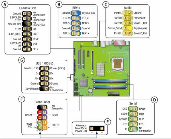
Mainboard Front Panel Connector Diagrams
If you buy a new computer motherboard it usually comes with an user manual. There you should be able to find the front panel header pinout information for the motherboard, sometimes the pinout diagram is printed on the motherboard too. But you may have trouble when changing the computer’s casing if you lost the manual and the pinout information is nowhere to be found on the board. Not all motherboards use the same front panel header pinout, you can search the Internet but it may be hard to find the correct pinout information if the motherboard is not a common model. I had such bad experience so I wrote this post for all the front panel connector diagrams that I ever used.
Computer front panel header is where the connectors of casing cables (reset button, power on/off button, power on light and hard disk activity light) and the motherboard are connected. Sometimes it includes speaker connector. But front USB, front audio, card reader are not included in this header because they have their own connectors.
Front panel header has many names:
- Front Panel Connector
- F_Panel
- JPanel
- JFP1
Computer front panel usually has these pins:
- POWER or POWER SW or ON/OFF
- RESET or RESET SW or RST
- MSG or POWER LED or POW LED or PLED
- HDD or HDD LED or HLED
- SPEAKER or SPK
- CI (chasis intrusion)
- +5V or NC (not connected) or RSVD (reserved) or DUMMY
On the diagrams below, the white text numbers mean there is no pin on the position.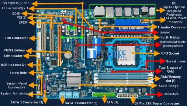
Front Panel 10 Pin | Some Call It 9 (or 10 – 1) Pin
This is the most commonly used pinout.
Motherboards that use this model front panel pinout are:
AFOX IH81-MA2-V2, ASRock 775VM800, ASRock Wolfdale1333-D667, ASUS H81M-K, Asus P5KPL-AM SE, ECS G41T-M16
Front Panel 20 Pin | Some Call It 12 (or 20 – 8) Pin
Motherboards that use this model front panel pinout are:
Asus P5KPL/EPU, Asus P5Q-EM, Asus P5Q SE2
Front Panel 20 Pin | Some Call It 13 (or 20 – 7) Pin
It is similar to the 10 pin (10-1) diagram but this one has a speaker connector.
Motherboards that use this model front panel pinout are:
Gigabyte GA-EP35-DS3, Gigabyte GA-EP43-UD3L, Gigabyte GA-G31M-ES2L
Front Panel 20 Pin | Some Call it 17 (or 20 – 3) Pin
This one has a CI connector and an additional LED for indication sleep mode.
Motherboards that use this model front panel pinout are:
Gigabyte GA-B85M-HD3-A, Gigabyte GA-G41M-Combo, Gigabyte GA-H61M-S2P
Front Panel 16 Pin | Some Call It 12 (or 16 – 4) Pin
The Power connector is on the center (pins 7 & 9).
Front Panel 16 Pin | Some Call It 15 (or 16 – 1) Pins
Motherboards that use this model front panel pinout are:
Biostar A55MLV, Biostar A75MG, Biostar G31M, Biostar G41D3C, Biostar H61MU3B, Biostar P4M900-M7 FE
Connecting Motherboard to Chassis
Home News & Reviews How to Connect Motherboard to Chassis Front Panel?
If you are building your first PC on your own and don’t know how to connect the front panel of the case to the motherboard, then in this article we will try to convey the information about connecting the front panel, USB ports, fans (installed in the case) to the motherboard as simply as possible.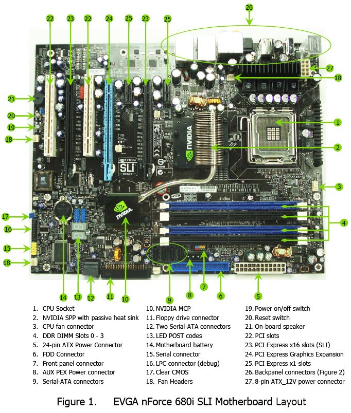
— HOW TO CONNECT THE MOTHERBOARD TO THE FRONT PANEL —
1. It is advisable to look into the (instruction) manual from the motherboard and see how the pins are connected to the motherboard.
2. If you don’t have it at hand or are just too lazy, you can go to the manufacturer’s website and type in the motherboard model into the search — there you will find the manual in electronic form.
3. If you don’t have the time or desire for that, just follow the instructions and you’ll be fine!
Do not worry if you connect something wrong — in the worst case, the connectors and buttons on the front of the case will not work until you connect them correctly.
— WHEN THERE IS NO MANUAL AT HAND —
(we use the instructions on the motherboard itself)
— all this needs to be connected to the motherboard.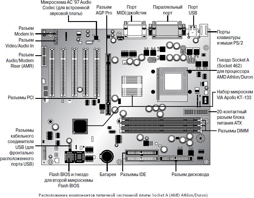 All cables have their own marking (inscription).
Before starting work, it is recommended not to connect the computer to the power supply to avoid a sudden power surge or accidental short circuit.
Previously, all standard wires from the body were colored, this slightly simplified the connection task.
Now all cables are black.
On all motherboards, the connection connectors are located in the lower right corner,
each connector is signed, above or below the expected
connection location.
Connectors available separated and combined with with SPEAKER connector — everything is absolutely identical (the same).
We proceed to the connection itself, take the cable in hand (I recommend the following connection sequence):
- RESET SW LED
- POWER SW
- POWER LED —
- POWER LED +
- SPEAKER — if required
Pay attention to each of the connectors there is a label (triangle), this is a plus (+) we find a label with a triangle on the motherboard + and connections.
remains not yet connected wires (from left to right):
- MoLAX — Cable of power, it will be if the front cooler (up to 3 pieces)
- USB 3.0 and 3 pieces are installed in the case. USB — cable for powering two connectors on the front panel
- HD Audio — The cable allows you to use the front headphones for headphones and micephone
- SATA — Building Sublight cable
— We will analyze the bonus — 9004 9002 PROUCT: MAG Z490 TOMAHAWK / PSU 600W
Manufacturer: MSI / Chieftec
- Cable MOLEX — connect to the cable from the power supply (now there are 3 coolers in the case) one, it is necessary to give power to it from the PSU.
-
- USB 3.0 — connect to the connector on the motherboard, it will be signed on the motherboard itself.

- USB — connect to any connector on the motherboard, again they will be signed.
- HD AUDIO — connect to the connector, which is located mainly in the lower left corner, it is also signed on the motherboard.
- SATA (male) — connect to the SATA (female) connector that comes from the power supply (3rd connector in the picture above).
— We start the PC and rejoice.
Connecting the power supply to the motherboard: 3 steps
Friends, I warmly welcome you to my next article-instruction. In touch Botan from WiFiGid. In my entire life, I have already assembled an unmeasured number of computers, but the most difficult thing that a beginner in this business can face is the final assembly. In this article, I would like to share with you my experience on how to properly connect the motherboard. Step by step, in pictures, for dummies.
But if you still have any questions or comments (the world is changing, articles sometimes become outdated) — welcome to the comments. We will discuss and update.
I also strongly recommend that you prepare instructions for your motherboard — in the form of a book or download from the Internet for your model. If the general steps are always clear, then the pinout of the front panel is sometimes not indicated on the board at all — you will have to read the instructions or spend time searching.
Photos on the example of my not very old ASUS B360K. But this does not affect the essence of the story.
Testing assembly
After successful assembly, we proceed to testing. It’s very normal if something doesn’t work. Just listening to sounds (if a speaker is connected) or reading messages on the screen with an interpreter is also a great option. The main thing here is not to be afraid.
General testing procedure:
- We turn on the power supply to the network — in some cases, the lights on the board light up. So the board is connected to the power supply correctly.
- Press the power button in front. If it doesn’t work, go to the front panel connection section and fiddle with the same small connector. But usually the backlight starts to burn, and the fans rotate.
- We immediately check the rotation of the fans: processor, video card, case fans. If something does not work, we look for the reason.
- While we were checking, the system (or at least the BIOS) should have already booted — if it doesn’t write anything bad or everything loaded, move on. As an example, information about missing disks can be written here (we check the cable and power) or the need to connect power to the video card. Sometimes squeaks begin — we listen to the speaker beeping, open the instructions for our board and only read the error codes there (roughly speaking, the systems differ, instructions from other boards may not be suitable).
 Sometimes it’s not at all clear — it turned out for me alone that the processor came out after the board, and the board in the drain did not know about its existence and gave an error. I had to look for an old processor that she knows, flash the BIOS, and after that everything started successfully. Watch, do not be afraid, if anything, negotiate with any service where there is iron at hand.
 - In the properties of the system, check the amount of RAM — everything must match the installed one.
- We look at the number of hard drives — if there was no logical partitioning, everything should correspond to the set.
- Connect to the front USB connector — for example, a mouse or keyboard. We check the work.
- Connect headphones to the front jack.
- Press the reset button.
Checks can be expanded further, but it is better to carry out this before the final closing of the case, so as not to climb inside again later. Here I am additionally running the system of the same AIDA64 for a stress test — to check the operation of the cooling, but this is not for everybody.