Ubuntu update for intel-microcode
Ubuntu update for intel-microcode
- Main
- Vulnerability Database
With exploit
With patch
Published: 2021-05-17
| Risk | Low |
| Patch available | YES |
| Number of vulnerabilities | 3 |
| CVE-ID | CVE-2020-8695 CVE-2020-8696 CVE-2020-8698 |
| CWE-ID | CWE-204 CWE-264 |
| Exploitation vector | Local |
| Public exploit | N/A |
| Vulnerable software Subscribe |
Ubuntu intel-microcode (Ubuntu package) |
| Vendor |
Canonical Ltd. |
Security Bulletin
This security bulletin contains information about 3 vulnerabilities.
EUVDB-ID: #VU48372
Risk: Low
CVSSv3.1:
CVE-ID:
CVE-2020-8695
CWE-ID:
CWE-204 — Observable Response Discrepancy
Exploit availability:
No
Description
The vulnerability allows a local user to gain access to potentially sensitive information.
The vulnerability exists due to observable discrepancy in the Running Average Power Limit (RAPL) Interface. A local administrator can gain access to sensitive information on the target system.
Affected products:
|
|
|
|
|
|
|
|
|
|
|
|
|
|
|
|
|
|
|
|
|
|
|
|
|
|
|
|
|
|
|
|
|
|
|
|
|
|
|
|
|
|
|
|
|
|
|
|
|
|
|
|
|
|
|
|
|
|
|
|
|
|
|
|
|
|
|
|
|
|
|
|
|
|
|
|
|
|
|
|
|
|
|
|
|
|
|
|
|
|
|
|
|
|
|
|
|
|
|
|
|
|
|
|
|
|
|
|
|
|
|
|
|
|
|
|
|
|
|
|
|
|
|
|
|
|
|
|
|
|
|
|
|
|
|
|
|
|
|
|
|
|
|
|
|
|
|
|
|
|
|
|
|
|
|
|
|
|
|
|
Mitigation
Update the affected package intel-microcode to the latest version.
Vulnerable software versions
Ubuntu: 18.04 — 21.04
intel-microcode (Ubuntu package): before 3.20210216.0u buntu0.21.04.1
CPE2.3
- cpe:2.3:o:canonical:ubuntu:20.10:*:*:*:*:*:*:*
External links
http://ubuntu.com/security/notices/USN-4628-3
Q & A
Can this vulnerability be exploited remotely?
Is there known malware, which exploits this vulnerability?
CVE-ID:
CVE-2020-8696
CWE-ID:
CWE-264 — Permissions, Privileges, and Access Controls
Exploit availability:
No
Description
The vulnerability allows a local user to gain access to sensitive information.
The vulnerability exists due to improper removal of sensitive information before storage or transfer in
some Intel(R) Processors. A local user can gain access to sensitive information on the system.
Mitigation
Update the affected package intel-microcode to the latest version.
Vulnerable software versions
Ubuntu: 18.04 — 21.04
intel-microcode (Ubuntu package): before 3.20210216.0u buntu0.21.04.1
CPE2.3
- cpe:2.3:o:canonical:ubuntu:20.10:*:*:*:*:*:*:*
External links
http://ubuntu.com/security/notices/USN-4628-3
Q & A
Can this vulnerability be exploited remotely?
Is there known malware, which exploits this vulnerability?
CVE-ID:
CVE-2020-8698
CWE-ID:
CWE-264 — Permissions, Privileges, and Access Controls
Exploit availability:
No
Description
The vulnerability allows a local user to gain access to sensitive information.
The vulnerability exists due to improper isolation of shared resources in some Intel(R) Processors. A local user can gain access to sensitive information on the system.
Mitigation
Update the affected package intel-microcode to the latest version.
Vulnerable software versions
Ubuntu: 18.04 — 21.04
intel-microcode (Ubuntu package): before 3.20210216.0u buntu0.21.04.1
CPE2.3
- cpe:2.3:o:canonical:ubuntu:20.10:*:*:*:*:*:*:*
External links
http://ubuntu.com/security/notices/USN-4628-3
Q & A
Can this vulnerability be exploited remotely?
Is there known malware, which exploits this vulnerability?
1. Introduction
An ISO file is a disk image file that contains the entire contents of a CD, DVD, or even a Blu-ray disc. Various tools are available to access these contents under Linux.
In this tutorial, we’ll explore different methods for extracting ISO images in Linux. We’ll also examine their execution time to find out which one is the fastest.
2. Using
mount
mount is a built-in tool in Linux that can be used to mount ISO files to access their contents.
Firstly, let’s make a directory:
$ mkdir /mnt/extract
Secondly, we’ll mount it as a loop device:
$ mount -o loop IsoFile.iso /mnt/extract/
Here, we use the -o flag of mount to specify the loop option. Now, the entire contents of our ISO file are accessible in the specified path.
3. Using
7z
7z is a file archiver that can extract contents from ISO files.
It’s part of the p7zip package. Let’s install it via yum:
$ yum install p7zip p7zip-plugins
Now, we can use the x option to extract a file. We’ll extract an ISO in the current directory:
$ 7z x IsoTest.iso
7-Zip [64] 16.02 : Copyright (c) 1999-2016 Igor Pavlov : 2016-05-21
p7zip Version 16.02 (locale=en_US.UTF-8,Utf16=on,HugeFiles=on,64 bits,2 CPUs Intel(R) Core(TM) i7-9750H CPU @ 2.60GHz (906EA),ASM,AES-NI)
Scanning the drive for archives:
1 file, 4980736 bytes (4864 KiB)
Extracting archive: IsoTest.iso
--
Path = IsoTest.iso
Type = FAT
Physical Size = 4980736
File System = FAT16
Cluster Size = 1024
Free Space = 2783232
Headers Size = 61440
Sector Size = 512
ID = 3481680618
Everything is Ok
Folders: 24
Files: 29
Size:       2119946
Compressed: 4980736
Firstly, the 7z command scans the ISO file. Then, it shows the path, the used filesystem, and other details. Next, we can see the message Everything is Ok and the number of extracted files and folders with sizes.
4. Using
bsdtar
bsdtar is a version of the tar command that supports additional archive formats. It’s included in a number of Linux distributions by default.
If required, we can still install it via our package manager:
$ yum install bsdtar
Then, we can extract an ISO file:
$ bsdtar -xf IsoFile.iso
As a result, we extracted the ISO file in the current directory. In this case, the x and f options were used. Among them, -x is for extracting to disk, while -f supplies the file we want to work with.
isoinfo can be used to extract all or specific files from ISO images. It just supports ISO-9660 (a filesystem for optical disc media).
It’s part of the genisoimage package. Let’s install it with yum:
$ yum install genisoimage
Once installed, we can list the content of an ISO file:
$ isoinfo -i myIsoFile.iso -l
Directory listing of /
d---------   0    0    0            2048 Oct 28 2015 [     29 02]  .
d---------   0    0    0            2048 Oct 28 2015 [     29 02]  ..
d---------   0    0    0            2048 May 26 2013 [     30 02]  BOOT
----------   0    0    0           96576 May  8 2022 [     49 00]  myFile.txt
Directory listing of /BOOT/
d---------   0    0    0            2048 May 26 2013 [     30 02]  .
d---------   0    0    0            2048 Oct 28 2015 [     29 02]  ..
----------   0    0    0        11424857 May  8 2022 [     49 00]  CORE.GZ;1
d---------   0    0    0            2048 Nov 30 2021 [     31 02]  ISOLINUX
----------   0    0    0         5081088 May  8 2022 [   5628 00]  VMLINUZ.;1
...
We used the -i option to specify the ISO-9660 image. Moreover, the -l option runs the equivalent of ls -lR inside of an ISO file and produces the output.
We can see each directory listed separately. Then, we can extract files via -x and the file path:
$ isoinfo -i myIsoFile.iso -x myFile.txt > myExtractedFile.txt
In this example, we extracted myFile.txt to a new file named myExtractedFile.txt. We can only use this command to extract a file, not directories.
6. Using
xorriso
xorriso is a utility that can be used to create, manipulate, and extract ISO files.
First, we’ll install it with our package manager:
$ yum install xorriso
Now, we can extract an ISO file:
$ xorriso -osirrox on -indev IsoFile.iso -extract / myExtractDirectory xorriso 1.5.4 : RockRidge filesystem manipulator, libburnia project. Copying of file objects from ISO image to disk filesystem is: Enabled xorriso : NOTE : Loading ISO image tree from LBA 0 xorriso : UPDATE : 11 nodes read in 1 seconds xorriso : NOTE : Detected El-Torito boot information which currently is set to be discarded Drive current: -indev 'IsoFile.iso' Media current: stdio file, overwriteable Media status : is written , is appendable Boot record : El Torito Media summary: 1 session, 8264 data blocks, 16.1m data, 38.1g free Volume id : 'Core' xorriso : UPDATE : 9 files restored ( 16148k) in 1 seconds = 11.9xD Extracted from ISO image: file '/'='/root/temp-01/myExtractDirectory'
To do so, we’ve used these options:
- osirrox on – enable the specific extension for the ISO filesystem
- indev – find the input file to extract
- extract iso_path disk_path – our actual command that extracts contents from iso_path to disk_path
As a result, we can see information about our media, the number of files, spent time, and others.
7. Measuring Times
In this section, we’re going to measure the total time taken by each command to find out which one is faster. We’ll use the time command for this. Moreover, we’ll skip the isoinfo command, as it can’t extract all ISO files.
Notably, the performance measurements in this section are based on a single run of each command. So, they may vary depending on various factors, including system configuration, hardware capabilities, and caching mechanisms. Hence, caching can play an important role in the results. Therefore, runs of the same commands may show different results if we don’t clear the cache and take other factors into account.
Let’s start with the mount command:
$ time (mount -o loop myIsoLive.iso /mnt/extract/ && cp -R /mnt/extract /home/newPath/)
...
real	0m9.260s
user	0m0.040s
sys	0m4.337s
The mount command only reads the filesystem’s header and doesn’t extract any data. Therefore, we combined the time taken for mounting with the time needed for copying the files from the mount point to another destination.
Afterward, we check the 7z command:
$ time 7z x myIsoLive.iso ... real 0m4.897s user 0m0.092s sys 0m2.927s
Then, we can check bsdtar:
$ time bsdtar -xf myIsoLive.iso
...
real	0m5.653s
user	0m0.115s
sys	0m3.075s
Finally, we’ll measure the time of xorriso:
$ time xorriso -osirrox on -indev myIsoLive.iso -extract / myExtract
...
real	0m5.367s
user	0m0.549s
sys	0m2.866s
In the result, we can see the actual times after the real label. Therefore, by comparing these values, we can see that the 7z command seems quicker than the others.
8. Conclusion
In this article, we discussed various ways to extract an ISO file in Linux.
Sometimes we might prefer to use a built-in command instead of installing new tools, so we tested mount. In other cases, we just need to extract a single file from an ISO image, instead of extracting the entire image file, or just want to use another tool. For each case, we compared the performance by using the time command.
Processor Intel QNCT(Coffee Lake ES, 6C/12T). Zalman VF700-Cu changes profession
QNCT processors have been on sale for a long time. They are laptop chips with a soldered adapter for installation in a regular motherboard. They have the performance of the i7-7700K at a bargain price of $70, but there are some nuances in the assembly, including the exactingness of the selection of the cooling system and the need to align its mounts.
I tried to combine good heat dissipation, compactness and ease of installation in one design.
The QNCT processor has 6 cores / 12 threads, operates at a base frequency of 2.0 GHz, automatically accelerates to 3.6 GHz per core or 3.1 GHz for everything in turbo boost, manually up to 3.3 GHz via BIOS or Intel XTU program. At the same time, its TDP is 45 W, and the performance is sufficient to fully utilize the capabilities of video cards of the GTX1070/1080 level.
An almost ideal option for a home PC, but, of course, it could not do without pitfalls:
Processors are demanding on motherboards. Least of all problems arise with boards from Gigabyte. On the B360, h410, h470, Q370 and Z390 chipsets, splicing does not start at the moment due to the peculiarities of the BIOS device. There are also some restrictions on the design and weight of applicable cooling systems — they must be with a solid metal base and as light as possible.
All these difficulties did not frighten me, and I placed an order.
The parcel was packed in a corrugated cardboard box, arrived in 2 weeks.
The useful contents of the package are a plastic box containing a clamping frame, 6 screws for fixing it and a processor wrapped in a napkin, and two Torx screwdrivers of different sizes. I didn’t take a picture of the puffy wrapping film 🙂
Processor-sandwich, top view. The crystal is sealed with Kapton tape to protect it from damage — do not forget to remove the tape before installing the cooler.
Same, bottom view:
This square dotted with contact pads fits into the connector on the motherboard, and everything else does not fit there, which is why I had to make a special frame. For comparison, there is a regular processor for Socket 1151: 9 nearby.0003
The installation of this processor consists of two stages.
At the first stage, the BIOS of the motherboard is finalized, since engineering processors require the corporate version of Intel ME and refuse to run on the user one (which is why processor fusions are not supported by systems based on the B360, h410, h470, Q370 and Z390 chipsets — they use ME 12.x, the corporate version of which is not publicly available, it is impossible to downgrade the ME version to 11.x). According to the developers, this is one of the steps to protect against the resale of such processors on the market, but the firmware of test motherboards has already been leaked to the Internet, unearthed, and special programs have been written to automate the refinement of custom firmware.
Some features of the refinement
ME — mandatory Corporate, otherwise the engineering processor will not start. The version is selected empirically, but it must be remembered that the available space is limited. Some motherboards (especially Asus) only require version 11.7. The Enabled / Disabled option under the ME selection disables it via the HAP-bit In most cases ME needs to be disabled, but some motherboards won’t start with the ME disabled. MSI will display a warning about ME being disabled, but this will not affect further operation.
Vbios+GOP — update to the latest version. Otherwise, the board will not start the video core of the processor and will not start (or the integrated graphics will not work).
Microcode — for QNCT you need microcode 906EA DE , we mark it in the list; those microcodes that are already in the firmware and / or desired for other processors — optional. In the final image, there will be only marked ones — the region is completely overwritten during finalization.
The serial number/MAC/UUID in Personal Data can be entered manually by yours, or the program can find them automatically in the BIOS dump. In principle, it is not critical for performance …
Save the finished image only in *.bin format for flashing by the programmer. Even for Asus. Especially for Asus — you can’t go anywhere without a programmer.
In general, to launch Coffee Lake processors on 100 and 200 series boards, it is also necessary to refine the processor socket, in which it is necessary to isolate some of the contacts and short-circuit some, but this has already been done in the internal wiring of the adapter that allows you to put the BGA1440 processor into the LGA1151 socket, so that it remains only to reflash the BIOS and install the cooler correctly.
If your motherboard is quite common, most likely there is already a modified BIOS for it. Under Gigabyte Z170N-WIFI, for example, it was found here.
If the board is relatively rare (this is especially true for any Chinese exotic), you have a choice: pick up a tambourine and try to mold the firmware in the CoffeeTime program yourself or write to the seller on Aliexpress in private messages and ask him for a file (or an already flashed chip, if it is on your board in the socket). He answers quickly, in about half a day the issue with the firmware is solved.
In the absence of a programmer, flashing the BIOS will have to be carried out on a standard desktop processor for the platform, such as Sky Lake. If region locking is not enabled in the original firmware of the motherboard, then there will be no particular problems, although the motherboard with DualBIOS will have to be changed twice.
If, when trying to flash, an error message 451 appears on the screen, the lock is still enabled.
This problem is solved quite simply — by pulling the HDA_SDO output on the audio codec of the motherboard to the + 3.3V bus at the time of switching on. The easiest way to do this is to short-circuit pins 1 and 5 on the sound chip (check the pin numbers before shorting them. For Realtek, the HDA_SDO pin is called SDATA_OUT, for VIA — SDO. The 3.3 V pin for Realtek is called DVDD, for VIA — DVDD_CORE):
I recommend using tweezers with thin sharp jaws for this and sealing the extra microcircuit pins (from 6 to 11) with adhesive tape before closing, so as not to accidentally short out the excess.
Now you need a little sleight of hand — with one hand we hold the tweezers on the leads, with the other we press the power button. When a beep sounds, the tweezers can be removed — until the reboot, the lock will be deactivated. If you are designing the firmware yourself, I recommend disabling FD locks in the CoffeeTime settings, because it’s not a fact that everything will start the first time.
Reflashed? We turn off the power from the board (physically, we pull out the cable from the power supply), remove the cooler, snap off the clamping frame of the processor socket.
We remove the processor. We take a larger screwdriver from those supplied with the processor, unscrew the three screws securing the clamping frame and remove the frame itself.
We put the processor in the socket.
We cover it with the attached frame. I received the frame of the old revision, the new ones leave only the crystal open.
We insert the mounting screws supplied with the processor into the holes and tighten them with a second screwdriver.:max_bytes(150000):strip_icc()/3LW4045927-3-5279aa56da7a4f429aabc35b0b2d2e3c.jpg)
This procedure did not cause any particular difficulties for me, just do not tighten the screws until the textolite crunches. If the BIOS was finalized on its own, it is most likely that he will be to blame for the failure to start the freshly assembled system.
We reset the BIOS (somewhere you need to rearrange the jumper on the pins for a few seconds, close the contacts on the board with a metal object somewhere), connect the power and remove the protective tape from the crystal. We apply thermal paste to the crystal and put a temporary heatsink on it, which can be borrowed from an old video card or chipset. Its task is to remove heat during the initial check, so fastening and blowing it are not necessary, just controlling its temperature with a finger is enough.
We press the power button. The first start will be quite long, the board will reboot several times, stopping and restarting the cooler. If everything was done correctly, then a single sound signal and the appearance of an image on the screen will occur before the radiator heats up to the point where it is impossible to keep a finger on it, and at this moment you can turn it off and proceed to the second stage of the assembly — installing the cooler. If there is no sound and image, we still turn off the power and see what was done wrong when finalizing the firmware, make changes, and then repeat the previous steps.
Since the QNCT processor and the like were originally designed for laptops, it does not have a metal cover to reduce the thickness of the product and reduce its cost — the crystal is located openly on the textolite. Coolers with direct contact of heat pipes are contraindicated for this, but now they have flooded everything and a good cooler, light and with an all-metal base, has already become difficult to find.
However, there is a solution — you can use coolers from old processors. QNCT is a cold processor, 45 watts of heat dissipation is more than enough for a cooler from Socket 478 of the very first revision — with solid longitudinal ribs.
.
It was attached to the board by the plastic frame surrounding the processor:
.
The mounting points, of course, do not match for Socket 478 and Socket 1151, so it will not work to rearrange the frame on a new motherboard:
Therefore, we cut out the mounting tabs from a 2 mm thick steel plate and fasten them to the radiator with M3 screws with a countersunk head.
After several iterations of fitting with a file in place, the radiator takes the following form:
It will be attached to the board with four spring-loaded screws. Yes, the washers and fastening nuts also had to be filed.
The spring-screw assembly looks like this:
If you decide to use a boxed cooler for Socket 115x, then you will also have to modify it, replacing the plastic pins with spring-loaded screws — the standard clip-on mount does not provide the necessary clamping of the heatsink to the crystal.
This spring-and-screw fastening is not free from shortcomings — it requires even tightening of the screws when installing the cooler on the chip.
Is there any way to get rid of this?
Can. A similar design solution with an open crystal is typical for video cards, and given the size restrictions, the cooler for them simply has to be compact. For example, Zalman once released the VF700 model.
It existed in two versions — VF700-AlCu with a mixed aluminum-copper heatsink weighing 180 grams and VF700-Cu with an all-copper heatsink weighing 270 grams.
The uniformity of heat removal is more important to us than savings 90 grams of mass, so VF700-AlCu with its narrow copper strip in the central zone of the radiator, which covers less than 1/3 of the heat transfer area, will not suit us:
I got the VF700-Cu with a problematic GeForce 6600GT, but in practice it turned out to be able to cope with the Athlon64X2 3600+ processor. Although I have never calculated for such an application and it will not be possible to put it directly on the processor, but when did it stop us?
One of the features of AMD processor sockets, starting with Socket 754, is a developed plastic backplate, to which a plastic frame is attached, for which the cooler itself is attached directly.
At the same time, the processors are equipped with a heat-distributing cover that protects the crystal from mechanical damage, so installing the Zalman VF700 cooler on them is very simple — just remove the plastic frame surrounding the processor socket, measure the distance between its fastening points diagonally, lengthen the arms of the rocker spring and pull them to backplate screws from native frame:
The accuracy of the spring extensions and the centering of the cooler on the processor does not play a special role — the heat-distributing cover of the processor levels out errors of a few millimeters. With an open processor gluing chip, this trick will not work — the cooler should be pressed against it as evenly as possible, so we will have to make a special adapter.
First, we pick up a ruler or caliper and measure the processor:
We find a description of the cooling system mounts for Socket 115x and attach to the drawing what we intended:
If the center of the chip of the stock processor was exactly at the intersection of the diagonals of the square formed by the centers of the holes for mounting the cooling system, then at the QNCT processor gluing it is shifted by 2 mm to the north and 3 mm to the east, and this must be taken into account when manufacturing the adapter — it will be asymmetric .
We take a piece of duralumin sheet 4 mm thick.
We mark up.
Kernim.
We drill holes with a diameter of 2.5 mm.
Sawing.
In two holes in the middle, we cut the M3 thread and countersink them for countersunk screws, drill holes in the corners to a diameter of 3. 0-3.2 mm.
At this point, paint residue can be removed with a wire brush.
From getinaks 5 mm thick we make 8 washers with an inner diameter of 3 mm and an outer diameter of about 10 mm.
The thickness of the washers is determined by the height of the motherboard components located next to the processor socket — the frame lying on the stacks of washers should not touch them.
In half of the washers, we countersink the hole with a 4.0-4.2 mm drill so that the washer fits on the backplate mounts and fits snugly against the PCB of the motherboard:
I used M3x14 screws with a wide pan head.
They are somewhat short, but M3x16 was not found.
We twist M3x12 screws with a countersunk head into the threaded holes of the frame, install the washers on the backplate attachment points, put the frame on top of them and tighten the screws of its fastening.
We lubricate the crystal with a thin layer of any
thermo paste, which is not a pity (you can even use a toothpaste), and put the cooler on the screws sticking out of the frame:
Then we remove it and look at the imprint of thermal paste on the sole.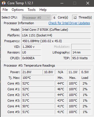 If it looks like this:
This means that the cooler did not get into the calculated position. We unscrew the frame, take a flat file and remove the chamfer from the upper edges of the cutout from the VRM side until the print takes the following form:
We wipe the crystal from the control paste, apply the working one:
We put the cooler on the screws and fix it. The Zalman VF700 comes with a pair of beautiful ribbed nuts (on the left in the photo):
But they are inconvenient, because the M3 thread in them is not through, and in the initial state its depth is not enough.
You can, of course, make spacers from tubes or put a stack of washers on each screw, but I was broke, so I just found a couple of aluminum racks for mounting printed circuit boards in the fastener stocks (on the right in the photo) — they just had enough thread depth. Mounts from PowerMac G5 processor nodes (pictured in the center) are also well suited — but they protrude upwards above the cooler, and in general the thing is quite exotic in our times.
On the experimental Z170N-WIFI board, it was not possible to achieve precise centering of the cooler on the chip due to the design features of the board — the cooler petals rest against the shield of the RG-45 connector protruding above the textolite and the WiFi adapter board without cutting them:
So — start!
Stress test:
At an air temperature in the room of 27 degrees, the processor heats up to 30-31 degrees at idle and up to 74 degrees at full load. Considering the size of the cooler, the result can be considered good, but it was achieved at the cost of rather high noise — the low-profile 80mm fan runs at full speed of 2880 rpm, and something needs to be done about it.
All modern motherboards are able to control the rotation speed of the CPU cooler using PWM. The fan speed control signal #CONTROL has an amplitude of 5 V and a frequency of about 22 kHz, taken from the output of the «open collector» type with a pull-up to +5 V …
But the fan of the Zalman VF700 cooler does not have a PWM speed control input, and the Gigabyte Z170N-WIFI motherboard cannot control the speed of fans with a three-pin connection.
To make them friends with each other, we will use a specially trained control unit.
It supplies the fans with direct current, the voltage of which depends on the duty cycle of the control signal. At the same time, the correct operation of the built-in tachometer is preserved.
Control box parts:
Low-power bipolar transistors VT1, VT2 — type MMBT3904 (marking 1N, * 1A, 1AM, pO4, wO4) — can be removed from old motherboards.
VT3 is a 25-30V P-channel MOSFET (p-MOS) in SO-8 package. I used TPC8126 — can be removed from the laptop battery controller board.
Diode VD2 — Schottky SS12 (1 A, 20 V). Capacitors C1 and C2 — 47-100 uF 16-20 V, preferably small-sized, tantalum,.
Inductor L1 — dumbbell, 500 μH, operating current of at least 1.5 A and DC resistance of not more than 0.5 Ohm — can be found on the board of an old inkjet printer or in the low-current channel of the ATX power supply.
The fuse F1 SMD version for a trip current of 1. 5..2 A can be removed from the old motherboard.
I decided to scratch the board with a cutter from a hacksaw blade. But there is also a template for LUT.
It turned out to be important not to overdo it with the inductance of the inductor, otherwise the control will not work.
Finished board:
We glue the board to the adapter frame with double-sided tape:
Fan voltage (blue line) versus speed control signal (yellow line):
The dependence of the fan supply voltage on the duty cycle PWM to the rotation speed control signal.
Stress test with adaptive fan speed control:
Temperatures rose slightly, but became noticeably quieter.
So, the disassembled cooling system:
Now let’s move on to performance tests.
CPU-Z report:
In single-threaded performance, the processor roughly corresponds to AMD Ryzen 5 1600, in multi-threaded performance — Intel i7-7700K:
Not a bad result for a processor with a TDP of 45W and a cost of $70.