Overclocking the Athlon XP-M 2500+ processor
THOSE OF YOU WHO REGULARLY PERUSE the news here at TR probably saw this item about the Athlon XP-M 2500+ and its recently discovered overclocking potential. The chips have become so popular so quickly that their street price has jumped 33% in recent days. Of course, given the accounts of overclocking to 2700MHz “on air” (using only a heatsink/fan) it’s no wonder they’re so popular.
Needless to say, we couldn’t sit this one out, so last week we ordered up an Athlon XP-M 2500+, and have spent the last 24 hours or so putting it through its paces. Read on to find out more about this overclocking wonder, and see how our particular chip fared.
XP-M: It’s not just for notebooks anymore
The first question in many people’s minds is: What’s up with putting a mobile chip in a desktop system? Well, there are a couple of important factors that make the XP-M such a desirable chip from an overclocking standpoint. The first is the default voltage of the chip. Desktop Athlon XP 2500+ chips run at a frequency of 1.8GHz using a default voltage of 1.65V. That’s fine for desktop systems that don’t have to worry about power consumption or battery life, but it’s a different story for mobile systems.
Because voltage relates directly to power consumption, one way to cut down on the amount of power used in a mobile application would be to lower the core voltage of the processor. Of course, it’s not quite that simple. Some 2500+ chips may continue to run properly at 1.8GHz if their core voltage is set below 1.65V, but others may become unstable or crash outright at anything below 1.65V. Every chip is different in this regard, and you won’t know until you try.
AMD does in fact use this method for the Athlon XP-M. Basically, they test their chips and determine which 2500+ chips can maintain their 1.8GHz clock speed properly with only 1.45V of core voltage instead of 1.65V. Chips that pass this test can then be set to a default voltage of 1. 45V and sold as Athlon XP-Ms. Essentially, the XP-M 2500+ is the cream of the crop within its speed grade. Not only can it do 1.8GHz, it can do it with one hand tied behind its back, so to speak.
Up close: our Athlon XP-M 2500+
Typically, overclocking is a crapshoot because you never know how fast a particular chip is going to go. There are many tales of people taking Pentium 4 2.4Cs and overclocking them to 3.2GHz or higher with ease, but we have an example in our labs that refuses to go any higher than 2.6GHz. Overclocking a processor is like a box of chocolates….
In the case of the Athlon XP-M, however, AMD has basically created a part consisting of cherry-picked processors. After all, if a 1.8GHz chip is good enough to stay at 1.8GHz even when undervolted by 0.2V, how much higher than 1.8GHz might it go at default voltage? This is one big reason for the XP-Ms popularity with overclockers; grab an XP-M, and you know you’re getting something good. The only question is: how good?
The second important mark in the XP-M’s favor is what’s missing: a multiplier lock. AMD mobile systems use the PowerNow! power management feature to conserve battery life. Unlike a desktop system, where bus speed times processor multiplier equals processor speed, things in a PowerNow! system are much more fluid. The processor has a minimum and maximum speed, and the system is constantly adjusting CPU speed based on processor load. If your system isn’t working very hard (you’ve gone to lunch, or you’re working on a Word document) the processor will limp along at 800MHz. Fire up a game, and it may jump up to 1500MHz and stay there until you quit. The speed is constantly updated relative to system load, and can be set to any number of intermediate speeds between the minimum and maximum.
One of the ways that the system works this magic is by manipulating the multiplier on the processor. Thus, in order for PowerNow! to work, the processor’s multiplier must be unlocked. Since PowerNow! is an important part of AMD’s mobile strategy, all Athlon XP-M chips are factory unlocked.
Add these two factors together, and you wind up with a guaranteed high-quality, unlocked Athlon XP core for only $25 more (at the time of this writing) than a “regular” Athlon XP 2500+. Whatta bargain!
Putting theory into practice
So now that we’ve looked at why the XP-M should be a good overclocker, let’s see if our hypothesis holds up to the test. Our subject is an Athlon XP-M 2500+, manufactured in week 49 of 2003, with a stepping code of IQZFA.
The markings on each chip betray its origins
We started out on an Asus A7N8X motherboard, and quickly got the CPU up to [email protected] on a 200MHz front-side bus with little drama. Any attempts to push harder, however, were met with failure, possibly because the A7N8X refused to crank the voltage any higher than 1.825V.
At that point, we switched over to Abit’s new nForce 2 Ultra 400 board, the AN7 (review forthcoming). The AN7 had no qualms about pushing the voltage up to and past our own comfort level. In the end, though, it didn’t make much difference with this chip. We managed to get [email protected] (yes, 1.96, that’s one of the settings on the AN7), but it wasn’t stable enough to complete our benchmark suite, so we decided to back down to 2.4GHz at 1.8V and run our benchmarks there.
Our open-air test bench with Abit AN7 motherboard and bone-stock air cooling
Abit’s uGuru utils kept us aware of our temps, shown here at 2.4GHz and 1.8V Although we didn’t hit the 2.7GHz+ levels that some others have apparently reached, let’s not lose sight of what we did accomplish. This is a 33% overclock resulting in a 200MHz advantage over an Athlon XP 3200+ (currently going for $195), from a chip that cost $98.
We decided against experimenting with bus overclocking, because our intent was to test the processor’s capabilities, and bus overclocking would’ve thrown too many other variables into the equation, such as non-standard PCI and AGP clock speeds. We said it before, but it bears repeating: One of the big advantages of the XP-M is its unlocked multiplier, which allows for substantial performance gains without having to resort to bus overclocking.
Our testing methods
As ever, we did our best to deliver clean benchmark numbers. Tests were run at least twice, and the results were averaged.
Our test systems were configured like so:
| Processor | Athlon XP-M 2500+ 2.4GHz | Athlon XP ‘Barton’ 3200+ 2.2GHz | Athlon XP ‘Barton’ 3000+ 2.167GHz | AMD Athlon 64 3000+ 2.0GHz AMD Athlon 64 3200+ 2.0GHz AMD Athlon 64 3400+ 2.2GHz |
AMD Athlon 64 FX-51 2.2GHz | Pentium 4 2.8’C’GHz Pentium 4 3.2GHz Pentium 4 3.2GHz Extreme Edition Pentium 4 3.4GHz Extreme Edition Pentium 4 2.8’E’GHz Pentium 4 3.0’E’GHz Pentium 4 3.2’E’GHz |
| Front-side bus | 400MHz (200MHz DDR) | 400MHz (200MHz DDR) | 333MHz (166MHz DDR) | HT 16-bit/800MHz downstream HT 16-bit/800MHz upstream |
HT 16-bit/800MHz downstream HT 16-bit/800MHz upstream |
800MHz (200MHz quad-pumped) |
| Motherboard | Abit AN7 | Asus A7N8X Deluxe v2. 0 0 |
Asus A7N8X Deluxe v2.0 | MSI K8T Neo | MSI 9130 | Abit IC7-G |
| BIOS revision | 1.4 | C1007 | C1007 | 1.1 | 1.1 | IC7_21.B00 |
| North bridge | nForce2 SPP | nForce2 SPP | nForce2 SPP | K8T800 | K8T800 | 82875P MCH |
| South bridge | nForce2 MCP-T | nForce2 MCP-T | nForce2 MCP-T | VT8237 | VT8237 | 82801ER ICH5R |
| Chipset drivers | ForceWare 3. 13 13 |
ForceWare 3.13 | ForceWare 3.13 | 4-in-1 v.4.51 ATA 5.1.2600.220 |
4-in-1 v.4.51 ATA 5.1.2600.220 |
INF Update 5.1.1002 |
| Memory size | 1GB (2 DIMMs) | 1GB (2 DIMMs) | 1GB (2 DIMMs) | 1GB (2 DIMMs) | 1GB (2 DIMMs) | 1GB (2 DIMMs) |
| Memory type | Corsair TwinX XMS4000 DDR SDRAM at 400MHz | Corsair TwinX XMS4000 DDR SDRAM at 400MHz | Corsair TwinX XMS4000 DDR SDRAM at 333MHz | Corsair TwinX XMS4000 DDR SDRAM at 400MHz | Corsair CMX512RE-3200LL PC3200 registered ECC DDR SDRAM at 400MHz | Corsair TwinX XMS4000 DDR SDRAM at 400MHz |
| Hard drive | Seagate Barracuda V 120GB ATA/100 | Seagate Barracuda V 120GB ATA/100 | Seagate Barracuda V 120GB ATA/100 | Seagate Barracuda V 120GB SATA 150 | Seagate Barracuda V 120GB SATA 150 | Seagate Barracuda V 120GB SATA 150 |
| Audio | Creative SoundBlaster Live! | |||||
| Graphics | Radeon 9800 Pro 256MB with CATALYST 4. 1 drivers 1 drivers |
|||||
| OS | Microsoft Windows XP Professional | |||||
| OS updates | Service Pack 1, DirectX 9.0b | |||||
All tests on the Pentium 4 systems were run with Hyper-Threading enabled, except where otherwise noted.
Thanks to Corsair for providing us with memory for our testing. If you’re looking to tweak out your system to the max and maybe overclock it a little, Corsair’s RAM is definitely worth considering.
The test systems’ Windows desktops were set at 1152×864 in 32-bit color at an 85Hz screen refresh rate. Vertical refresh sync (vsync) was disabled for all tests.
We used the following versions of our test applications:
- Cachemem 2.65MMX
- SiSoft Sandra 2004 (9.89)
- Compiled binary of C Linpack port from Ace’s Hardware
- Discreet 3ds max 5.
 1 SP1
1 SP1
- NewTek Lightwave 7.5
- Cinebench 2003
- POV-Ray for Windows v3.5
- PICCOLOR v4.0 build 472
- SPECviewperf 7.1.1
- ScienceMark 2.0 beta (23SEP03 build)
- Sphinx 3.3
- LAME 3.95.1 (build from mitiok.cjb.net)
- Xmpeg 5.0.3 with DivX Video 5.11
- FutureMark 3DMark03 build 340
- Comanche 4 demo
- Quake III Arena v1.31
- Serious Sam SE v1.07
- Unreal Tournament 2003 demo v.2206
- Wolfenstein: Enemy Territory v2.55
The tests and methods we employ are generally publicly available and reproducible. If you have questions about our methods, hit our forums to talk with us about them. Before we proceed, I’d like to give mad props to Damage on this one. He helped me out immensely in getting this article done as quickly as possible, by running the benchmarks and taking the pictures, among other things.
Memory performance
Overclocked or not, the Athlon XP is getting long in the tooth, and it especially shows in the area of memory bandwidth. The XP-M comes in right where we’d expect, tied with the XP 3200+ (which shares its 400MHz bus speed) and beating only the XP 3000+ with its 333MHZ front-side bus. The XP chips just don’t have the juice to compete with 800MHz front-side busses and on-die memory controllers.
The 2.4GHz XP-M outpaces all of the AMD chips by a good margin, at least until the matrix sizes get outside its 512KB L2 cache. At larger matrix sizes, however, the Hammer chips’ 1MB L2 cache and on-die memory controller lay down a beating on the XP-M.
A slight jump in clock speed over the XP 3200+ gives the XP-M a slight edge in memory access latency, putting it ahead of the 3.4GHz EE and the 2.8GHz Prescott as well. Still, things are pretty bunched up here in the middle of the graph, and the Hammer systems just embarrass everything.
Unreal Tournament 2003
The XP-M jumps a couple of spots relative to the XP 3200+, eclipsing the 3GHz Northwood and 3.2GHz Prescott in one of the tests. Ah, the difference 200MHz makes.
Quake III Arena
Quake III Arena loves memory bandwidth. Repeat it like a mantra. The Athlon XPs get romped on by everything here, and the XP-M’s extra clock speed only helps it beat up on its little brothers.
Wolfenstein: Enemy Territory
The XP-M puts in a better showing here, beating out a couple of P4’s, but it’s a long way off the Hammer chips.
Comanche 4
Enjoy this video game based around the Comanche helicopter, because it’s not likely you’ll be seeing one in real life anytime soon. At any rate, the XP-M earns a respectable finish here, though it loses to a number of Northwoods and all the Hammer chips. For the record, Comanche 4 really, really hates Prescott.
Serious Sam SE
The XP-M does exceptionally well in Serious Sam, beating out all Intel comers with less than two megs of cache. It basically ties the 3.4GHz Northwood in spite of a one gigahertz clock deficit. Can you say IPC?
3DMark03
The composite 3DMark scores put the XP-M near the bottom, but if you throw out the XP 3000+ and its 333MHz front-side bus, there’s less than 300 points separating worst from first. On the CPU tests, the XP-M makes a respectable showing, even taking down a Hammer in one of the tests.
Sphinx speech recognition
Ricky Houghton first brought us the Sphinx benchmark through his association with speech recognition efforts at Carnegie Mellon University. Sphinx is a high-quality speech recognition routine that needs the latest computer hardware to run at speeds close to real-time processing. We use two different versions, built with two different compilers, in an attempt to ensure we’re getting the best possible performance.
There are two goals with Sphinx. The first is to run it faster than real time, so real-time speech recognition is possible. The second, more ambitious goal is to run it at about 0.8 times real time, where additional CPU overhead is available for other sorts of processing, enabling Sphinx-driven real-time applications.
Sphinx loves the memory bandwidth, and the results aren’t pretty for the XP chips.
LAME MP3 encoding
We used LAME to encode a 101MB 16-bit, 44KHz audio file into a very high-quality MP3. The exact command-line options we used were:
lame –alt-preset extreme file.wav file.mp3
LAME is about raw processing power and little else, and the XP-M’s high clock speed and high IPC leave it tied for fourth place with the 3.2GHz Northwood.
DivX video encoding
Ouch. Clearly the Athlon XPs are out of their league here, trailing the rest of the pack by a significant margin. Obviously, Xmpeg likes the P4. A lot. In fact, I saw them kissing under the bleachers. OK, I made that last part up, but it could’ve happened.
3ds max rendering
We begin our 3D rendering tests with Discreet’s 3ds max, one of the best known 3D animation tools around. 3ds max is both multithreaded and optimized for SSE2. We rendered a couple of different scenes at 1024×751 resolution, including the Island scene shown below. Our testing techniques were very similar to those described in this article by Greg Hess. In all cases, the “Enable SSE” box was checked in the application’s render dialog.
The XP-M does better than one might expect here, as the 200MHz clock speed advantage puts it over not only the XP 3200+, but also the 2.8GHz Prescott and two Athlon 64 chips.
Lightwave rendering
NewTek’s Lightwave is another popular 3D animation package that includes support for multiple processors and is highly optimized for SSE2. Lightwave can render very complex scenes with realism, as you can see from the sample scene, “A5 Concept,” below.
To test the effects of Hyper-Threading, we’ve tested the Hyper-Threaded processors with one, two, and four rendering threads. For non-Hyper-Threaded processors, we just tested with one and two threads.
Ouch. The Athlon XP chips just take a beating here; there’s no other way to put it. The XP-M just takes, umm, a slightly less severe beating.
POV-Ray rendering
POV-Ray is the granddaddy of PC ray-tracing renderers, and it’s not multithreaded in the least. Don’t ask me why—seems crazy to me. POV-Ray also relies more heavily on x87 FPU instructions to do its work, because it contains only minor SIMD optimizations.
POV-Ray is all about old school x87 math, and the results certainly show it. The mighty 3.4GHz P4 EE is laid low by the Athlon XP 3000+, as AMD just runs the table. For its part, the XP-M comes within a second of the top spot.
Cinebench 2003 rendering and shading
Cinebench is based on Maxon’s Cinema 4D modeling, rendering, and animation app. This revision of Cinebench measures performance in a number of ways, including 3D rendering, software shading, and OpenGL shading with and without hardware acceleration. Cinema 4D’s renderer is multithreaded, so it takes advantage of Hyper-Threading, as you can see in the results.
The XP-M actually ties with the FX-51 here, but that’s not saying much; the P4 and its Hyper-Threading just dominate here.
The other Cinebench tests aren’t multithreaded, so the Athlons do much better. The XP-M finishes in the middle of the pack.
SPECviewperf workstation graphics
SPECviewperf simulates the graphics loads generated by various professional design, modeling, and engineering applications.
The XP-M bounces around on the SPECviewperf tests, finishing as high as sixth in one test and third worst in another.
ScienceMark
ScienceMark 2.0 is optimized for SSE, SSE2, 3DNow! and is multithreaded, as well. The molecular dynamics simulation models “the thermodynamic behaviour of materials using their forces, velocities, and positions”, according to the ScienceMark documentation.
Primordia “calculates the Quantum Mechanical Hartree-Fock Orbitals for each electron in any element of the periodic table.” In our case, we used the default element, Argon.
The XP-M does extremely well here, finishing fourth place or better in all tests and winning the Cipher benchmark outright.
These last two tests, SGEMM and DGEMM, measure matrix math performance using several different codepaths optimized with several instruction set extensions, including SSE, SSE2, and 3DNow!
The Athlon XPs lag the rest of the entrants in Blas SGEMM, but redeem themselves nicely in Blas DGEMM.
picCOLOR image analysis
We thank Dr. Reinert Muller with the FIBUS Institute for pointing us toward his picCOLOR benchmark. This image analysis and processing tool is partially multithreaded, and it shows us the results of a number of simple image manipulation calculations. The overall score is indexed to a Pentium III 1GHz system based on a VIA Apollo Pro 133. In other words, the reference system would score a 1.0 overall.
The new version of picCOLOR we’re using today is optimized for SSE and SSE2, so it should perform differently than past revisions.
The XP-M does pretty well, beating out all of the non-EE Northwood chips. Here are the individual test scores for some of our key participants.
The XP-M gets whacked in GraphCopy, but finishes respectably in the other tests. For whatever reason, it absolutely owns the Video+Trgn test.
Conclusions
So to sum up, what we have here is a $98 CPU with a full 600MHz of overclocking headroom. What’s not to like? Sure, usually when we’re talking about overclocking, we issue the standard disclaimer: Every chip is different, your results may vary, yadda yadda yadda.
In this case, however, we feel like we should issue a disclaimer for the disclaimer, because everything about the XP-M suggests that the odds are in your favor. You don’t have to worry about getting a poor overclocker, because you’re guaranteed to get an undervolted chip. You don’t have to worry about a multiplier lock because you’re guaranteed to get an unlocked chip.
The only question, then, is how good is it going to get? Anecdotal evidence (based on our results as well as the Overclockers.com CPU database) suggests 2400-2700MHz is typical. AMD may not have intended it this way, but if you asked an overclocker what they would want in the perfect overclocking chip, they might very well describe the Athlon XP-M 2500+.
AMD Athlon XP-M 2500+ processor review: CPU specs, performance benchmarks
Buy on Amazon
Athlon XP-M 2500+ processor released by AMD; release date: January 2001. The processor is designed for laptop-computers and based on Barton microarchitecture.
CPU is locked to prevent overclocking. Total number of cores — 1. Maximum CPU clock speed — 1.86 GHz. Manufacturing process technology — 130 nm. Cache size: L1 — 128 KB, L2 — 512 KB.
Supported socket types: A. Maximum number of processors in a configuration — 1. Power consumption (TDP): 45 Watt.
Benchmarks
| PassMark Single thread mark |
|
|
|||
| PassMark CPU mark |
|
|
| Name | Value |
|---|---|
| PassMark — Single thread mark | 546 |
| PassMark — CPU mark | 346 |
Specifications (specs)
| Architecture codename | Barton |
| Launch date | January 2001 |
| Place in performance rating | 2723 |
| Vertical segment | Laptop |
| Die size | 101 mm |
| L1 cache | 128 KB |
| L2 cache | 512 KB |
| Manufacturing process technology | 130 nm |
| Maximum frequency | 1. 86 GHz 86 GHz |
| Number of cores | 1 |
| Transistor count | 63 million |
|
|
|
| Max number of CPUs in a configuration | 1 |
| Sockets supported | A |
| Thermal Design Power (TDP) | 45 Watt |
Experience of 2500 implantation of semi-rigid penile prostheses for erectile dysfunction
Kogan M.I., Krasulin V.V., Sizyakin D.V., Shangichev A.V., Glukhov V.P.
Department of Urology and Human Reproductive Health with a course of pediatric urology-andrology, Rostov State Medical University of the Ministry of Health of Russia, Rostov-on-Don Address: 344022, Rostov-on-Don, per. Nakhichevansky, 29, tel. (863)2014448 E-mail: [email protected], [email protected], [email protected], [email protected]
Introduction
For the male half of our planet, sexual dysfunctions are an extremely urgent problem, the significance of which has been steadily increasing in the last 50 years, moving from a narrow intimate to a global one, which is on a par with fundamental medical and social problems. More than 30% of men aged 18 to 59 have sexual dysfunction [1, 2].
Revision of the structure of sexual disorders with a tendency towards an increase in organic forms of the disease has led to an increasing recognition of surgical methods for the treatment of erectile dysfunction, among which phalloendoprosthetics occupies an important place [1, 3, 4].
Materials and methods
The first Russian sample of a semi-rigid silicone prosthesis was developed by us in 1981. Since that time, patients aged 21 to 78 years with organic forms of erectile dysfunction have undergone 2,500 penile intracavernous implantation operations.
Results and discussion
The technique of intracavernous implantation of prostheses into the penis from the most commonly used proximal approach is as follows:
On the back of the penis, at its base, we make a longitudinal median incision 3-5 cm long. In a sharp way, we peel off the skin and underlying membranes from the dorsal-lateral surface of the right cavernous body. We take the albuginea on the holders and dissect it longitudinally by 3-4 cm. In the distal direction, we bougie the right cavernous body to the geometric center of the head, and then in the proximal direction — until it stops with Hegar’s dilators, starting from No. 6 to No. 11-12. With the help of a bougie and a ruler, we measure the length of the distal and proximal tunnels, add up the dimensions and get the length of the entire cavernous body. We choose from the available assortment the prosthesis corresponding to the length and diameter of the cavernous body, while monitoring the strict correspondence of the length of the distal part of the prosthesis and the visible part of the penis. The prosthesis is introduced first into the distal, and then, bending it, into the proximal part of the tunnel. We control the correct location of the prosthesis and suture the wound of the albuginea with a continuous monolithic suture. A similar technique is also used for prosthesis implantation in the left cavernous body [3].
Our extensive experience in implantation of penile prostheses of our own design allows us to determine the technical points that determine the frequency of complications and the success of the operation:
- tunneling of the cavernous bodies of the penis must be carried out strictly in the anterolateral direction;
- the required length of the prosthesis for implantation must be measured for each corpora cavernosa;
- the use of prostheses with circular grooves provides good stabilization of the implants;
- the location of the narrowest part of the prosthesis at the base of the penis ensures its good mobility and comfortable styling under clothing;
- the implant should not completely obturate the cavernous body due to the risk of tissue ischemia.

Implantation of prostheses in the penis with erectile dysfunction, according to our data, provides the possibility of introjection and friction in 100%, and the ability to regularly have sexual intercourse makes it possible to achieve sexual satisfaction for both partners in 84% of cases. Family breakup prevented in 82.9%, and the strengthening of marital relations was achieved in 68.5% of cases.
Strict adherence to technical procedures reduced the complication rate from 23% to 2.4%. Analysis of complications of 2500 operations in the period from 1981 to 2013. presented in table 1.
Table 1. Complications of implantation of penile prostheses in the period from 1981 to 2013
| Complications | 1981-1985 | 1986-2000 | since 2001 |
|---|---|---|---|
| Subcutaneous hematoma | 2. 5% 5% |
1.5% | 1.8% |
| Prolonged swelling of the penis | 4.0% | 0.5% | – |
| Damage to the neurovascular bundle | 1.0% | 0.5% | – |
| Injury to the urethra | 1.5% | 0.8% | – |
| Perforation of the albuginea | 1.0% | 1.2% | 1.0% |
| Paraphimosis | 2.0% | – | – |
| Infection of the denture bed | 3.9% | 2.5% | 0.5% |
| Prolonged penile pain | 7.8% | 1.5% | 0.5% |
| Denture prolapse | 9.5% | 2.5% | 0.8% |
| Broken dentures | 10.0% | 3.0% | 1.5% |
Terminals
Thus, implant surgery using self-designed semi-rigid silicone prostheses, especially when conservative treatment is ineffective, largely solves the problem of treating erectile dysfunction.
Literature
1. Kogan, M.I. Erectile dysfunction / M.I. Kogan. — Rostov-on-Don.: Book, 2005. — 335 p.
2. Laumann, E.O. Sexual dysfunction in United States: prevalence and predictors / E.O Laumann., A. Paik, R.C. Rosen // J.A.M.A. — 1999. — Vol.281. – P.537544.
3. Krasulin, V.V. Surgical treatment of erectile impotence / V.V. Krasulin, S.M. Serebrennikov — Rostov-on-Don.: GinGo, 1994. — 96 p.
4. Montorsi, R.M. The aging male and erectile dysfunction / R.M. Montorsi, A. Salonia, F. Deho et al. // World J. Urol. — 2002. — Vol. 20 — No. 1. – P.28-35.
Article published in the journal «Bulletin of Urology». No. 2/2013 pages 27-29
Topics and tags
Erectile dysfunction
Journal
Bulletin of Urology No. 2/2013
To send comments, you must
to come in
or register
Field georadar OKO-3 | Sounding up to 0.
 4 m.0207 NON-DESTRUCTIVE GPR METHODS IN ENGINEERING SURVEYS
А.М. Kulizhnikov, A.A. Belozerov (RosdorNII)
Since the late 1990s. In Russia, georadar methods began to be widely introduced into the technology of engineering and geological surveys. Based on the results of georadar scanning, a continuous wave image (radarogram) is obtained, which is processed and interpreted by a special program in the context of the medium. Georadar technologies have such advantages as obtaining a continuous section using a non-destructive and environmentally friendly georadar method.
Ground penetrating radars are devices based on directing a short duration electromagnetic wave into multilayer media, receiving and converting the reflected signal. GPRs operate at temperatures from -40°C to +40°C. The devices are compact and do not differ in large mass (1.5-15 kg). They have high productivity when recording the environment in the field (from 5 to 30 km per shift), however, they require processing in office conditions (before changing to 500-1000 m of the section). At the same time, ground penetrating radars require verification drilling or pitting.
Ground penetrating radars are widely used in the road, airfield and railway industries, industrial, civil and hydraulic engineering, archeology, etc. Let us dwell on the experience and results of using ground penetrating radars at the Arkhangelsk State Technical University, at the State Enterprise RosdorNII.
These works were carried out by OKO-2 georadar with antenna units having a central frequency of 90, 150, 250, 400, 1200 and 1700 MHz. Different values of the central frequency make it possible to obtain different sounding depths (from 30.0 m to 0.8 m, respectively) at different resolutions (from 0.5 m to 0.01 m, respectively).
ENGINEERING AND GEOLOGICAL SURVEYS FOR THE DESIGN OF OBJECTS
A survey of the section of the Kola — V. Tulomsky highway — the Lotta checkpoint in the Murmansk region was carried out. The georadar was used for longitudinal passage along the axis of the originally planned route and for scanning the cross-sections to the axis of the route after 50 m. In order to verify the georadar work, pitting was carried out. The results showed that georadar work can be performed in a forest area with a hummocky and swampy surface. On the sections, the boundaries of the layers, the position of the groundwater level (GWL) were identified. The resulting sections were used by the designers when adjusting the design line of the route.
In addition, in 2003 the design of approaches to the bridge across the river was completed. Pronya in the Ryazan region and the geological structure was determined both along the longitudinal axis and along the diameters after 50 m on the ring road bypassing St. Petersburg.
EXPLORATION AND EVALUATION OF RESERVES OF BUILDING MATERIALS IN QUARIES
The reserves of road construction materials in the open pit Oktyabrsky Vytegorsky district of the Vologda region were assessed. Based on the results of the work, the remains of the reserves of the boulder-pebble mixture in the developed quarry were determined and the reserves of the useful stratum were established during the expansion of the quarry. Attempts to use GPR for exploration of sand reserves without control drilling were unsuccessful due to insufficient experience in separating conditioned sands from silty sands and sandy loams using field radargrams.
The Pestsovoye sand deposit in the Yamalo-Nenets region was assessed. The work was carried out on the floodplain sections of the rivers, where it was necessary to determine the boundaries both in terms of plan and in terms of the depth of conditioned sand. More than 14 km of longitudinal sections were filmed (Fig. 1) and conclusions were drawn on the volume of sand reserves. The accumulated practical two-year experience on field radarograms made it possible to identify areas with conditioned sands.
The reserves of sand materials for the maintenance of roads in 4 small quarries in the Murmansk region, ranging from 2 to 8 hectares, were also estimated. The work was carried out with a minimum of verification drilling (1-2 wells per quarry). Based on the results of the work, the reserves of useful stratum and overburden were determined, and the location of the GWL was also determined.
GEOPHYSICAL SURVEYS IN SURVEYING HIGHWAYS
More than 1000 km of highways were surveyed in order to identify the causes of destruction of sections and assign effective types of repair work. Among the surveyed sections, one can distinguish such federal roads as Moscow — Arkhangelsk, Moscow — St. Petersburg, Moscow — Minsk, Ring Road bypassing St. Petersburg. Motor roads were also surveyed in the Arkhangelsk, Vologda, Murmansk regions (Fig. 2), in the Komi Republic, in Yaroslavl and others. During the survey of roads, the thicknesses of the structural layers of the road pavement, the thickness and types of soils of the subgrade and underlying base, the uniformity of the materials of the pavement and subgrade soils, local weakenings (voids, suffusion zones, waterlogged areas of soils), areas of infiltration of surface and groundwater, spatial the geometric outline of aquicludes, the position of underground utilities.
Monitoring surveys of roads also determined the moisture content of subgrade soils (Fig. 3), the depth of freezing and thawing of soils, the location of the slip curve in landslide areas, the position of the groundwater level, etc.
The thickness of the upper layers asphalt concrete, installed by GPR scanning, was used to determine the possible depth of milling during the repair of road sections.
QUALITY CONTROL
The first experience of quality control was obtained in 2001, when on the section of the Arkhangelsk-Belogorsky highway, on the instructions of the customer, based on georadar scanning, the volume of hidden work was determined — backfilling at the peat site.
Quality control works were carried out on the Ring Road bypassing St. Petersburg. Here, the quality of the jet-cement piles was controlled (the number of piles, their diameter, landing on the mineral bottom, the continuity of the piles), as well as the condition of the subgrade, filled in the winter, and the thickness of the structural layers of the pavement.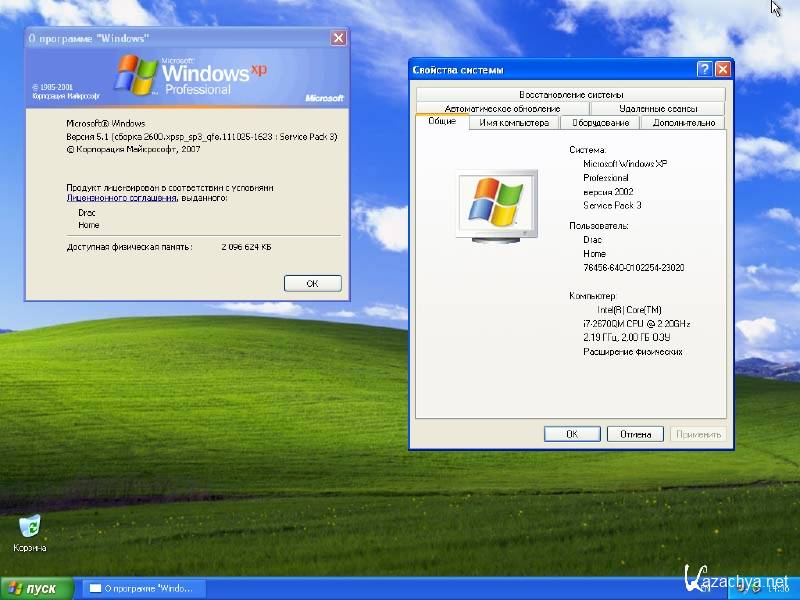 Thus, when assessing the state of the subgrade, zones of future sedimentation of the subgrade soil were identified, as well as places where frozen clods of soil were recorded.
In the section of the northern bypass of Ryazan, using georadar, the problem was solved to determine the subsidence of the subgrade under embankments 10-12 m high.
, was a possible infiltration of underground water through the body of earth embankments on dams, followed by settlement of structures.
Work was carried out on the section of the Marfin Brod dam in the Mozhaisk district of the Moscow region. To a depth of more than 13 m, the roof and bottom of the layers were determined, the uniformity of the embankment soils was assessed, and zones of possible groundwater infiltration were identified.
The Company also carried out work on the section of the dam in the town of Lyudinovo, Kaluga Region. Embankments, the concrete foundation in the upstream and downstream of the dams, erosion and water infiltration zones under the foundation were examined here. At the same time, the work was carried out by pulling the georadar in a rubber boat both along the surface of the water and in a waterproof case along the bottom at a water level of up to 4 m. Based on the results of the work, areas of possible water infiltration were determined, the quality of the concrete foundation was assessed, and places of local weakening were identified.
SURVEYS OF RUNWAYS AND APRONS OF AERODROMES
Like sections of highways, airfield facilities also need surveys. Ground-penetrating radar work performed on sections of taxiways and aprons at Domodedovo Airport made it possible to identify the causes of cracks in the concrete pavement, determine the moisture content of the subgrade soil, and determine the location of underground utilities. The reason for the formation of cracks was the drains laid at a depth of 1.5-2.0 m. The drains, due to the large accumulation of water around, led to the formation of cracks caused by the forces of frost heaving of soils (Fig. 4).
4).
INSPECTION OF BUILDINGS
Quite often, cracks form in the concrete floors of warehouses. In this case, questions arise: how to repair concrete floors, what is the reason for the formation of cracks? Such work was carried out at the Vnukovo aircraft repair shop, at the plant named after. Ukhtomsky (Lyubertsy). Based on the results of GPR scanning, voids and waterlogged zones of soils under concrete, as well as the thickness of the concrete floor, were determined. This allowed us to make the right decisions on the appointment of effective types of repair work.
Another work was to identify the reasons for the flooding of the basement in the building of the Road Administration of the Ryazan Region. Georadar surveys made it possible to identify a place under the building, which is a source of excessive moisture. In this place, as it turned out, there was an old stub of the heating network, which did not stand the test of time.
The accumulated long-term experience of georadar work allows us to conclude that non-destructive georadar methods are high-performance, environmentally friendly and are effectively used in many industries.