DRAM Light on Motherboard — How to FIX
by Mike Ethan
Your PC stopped working, or are you just now assembling your computer components? Today, we will figure out what the DRAM light on the motherboard means and how to fix it.
The DRAM light does not light up for no reason, so probably something wrong is happening.
Table Contents
- Warning
- DRAM Light on Motherboard – Finding a problem
- The Motherboard and compatible CPU
- DRAM Light on Motherboard – CPU
- How do I check if your Heatsink bent CPU socket pins?
- Conclusion
- Frequently Asked Questions
Warning
Please be aware that this is entirely at your own risk. We take no responsibility if anything happens to your PC components during the procedures. We have succeeded, but it could happen otherwise.
DRAM Light on Motherboard – Finding a problem
In such failures, it is best to start with a simple thing. I mean things that don’t require much disassembly because sometimes the problem can be more straightforward than expected.
If the computer has been in use for a long time and no component change was made, you most likely have a bad RAM stick or connector on the motherboard. Also, there are cases when an issue where the power supply is not connected to the GPU causes RAM light problems.
The main problems of DRAM Light are CPU, motherboard and RAM. So we are suggesting starting with RAM and Motherboard.
Method 1 – Try another RAM stick
If you have another RAM stick, you can try to change it. In this case, you will know if your RAM stick is working correctly. Next, examine the removed RAM stick, check the ram connectors for dirt, and check the motherboard plug. Maybe there is a lot of dust that needs to be removed.
Method 2 – Swap RAM Sticks
If you have dual channel RAM sticks, try to change from A1, A2 to A1, B1. In this case, you will know if your connection on the motherboard is working correctly.
Method 3 – Leave just one RAM stick
If you have 2 or 4 slots for RAM sticks, try removing all available RAM modules and use only one RAM stick.
Method 3 – Clear CMOS
- Turn off the computer and unplug the power cord from the computer.
- Remove flat, COIN size battery from the motherboard.
- Hold the computer power button for 30 seconds 3 times (some say the power button holds less, but it’s better to be confident).
- Put the CMOS battery back and power on the PC to see what happens.
If you are clearing the CMOS battery, that means you are resetting the BIOS settings to default. The CMOS battery is responsible for motherboard configuration, time etc. You can also check CMOS battery voltage if you have a voltage meter. It should be around 3 volts.
The Motherboard and compatible CPU
If you are building a new PC, there is a chance that your motherboard does not support your current CPU. To check it out, you can visit this page – CPU-Upgrade. You can select the motherboard on this page and then see which CPUs are supported by your motherboard. If your CPU is not listed, it means your motherboard does not support your CPU.
DRAM Light on Motherboard – CPU
Bent CPU or Motherboard pins can be an expensive problem. It is also known that bending CPU pins can cause a variety of anomalies on the computer. For example, sometimes, the CPU cooler is fitted too tight. In this case, the CPU is pressed very hard against the motherboards PINS and bends them.
How do I check if your Heatsink bent CPU socket pins?
- Remove CPU heatsink/cooler.
- Remove CPU.
- Inspect the CPU pins if you have an AMD CPU. Inspect Motherboard CPU socket PINS if you have an INTEL CPU.
Even a slightly bent CPU or Motherboard PINS can cause a big problem. If you notice a slightly bent pin and have a magnifying glass and steady hands, you can try to fix it yourself. This is a complex procedure that requires a needle or plastic card.
Before trying to unbend a PIN, you can always consider an option – take it to a PC repair guy. Because a broken PIN almost always means that the component is dead.
Bent CPU socket pin and needle
Inspect the remaining PINS through the magnifying glass to see bent. By inspecting the PINS, you will know what angle they are bent and how they should stand. Such work requires time and diligence. Then, very carefully, try to unbend the pin into its original position without significant pressure.
Our tech guy Linus made a great video on how bent socket pins back to their place.
Author Recommended Reads:
- Dropped RAM stick. Easy fragile?
- Thermal Paste on CPU Pins / EASY FIX
- CPU Stuck to Cooler / Easy Fix
- LCFC Debug Page Information. Old BIOS?
Conclusion
As you understand, the DRAM light on the motherboard can be caused by a variety of problems, but after checking all the problems we have listed, you will most likely find a solution. If you have not found a solution, or it was different – feel free to write in the comments, and then we will try to help you as soon as possible.
Frequently Asked Questions
DRAM Light on and no display
You should first try plugging the GPU cable into the motherboard. Then, of course, if you have a CPU with an INTEL HD graphics interface, you will know if there is a problem with the GPU.
If it makes a beeping sound, that means your PC is trying to tell you something. If there is no BEEP sound, maybe your motherboard doesn’t have a speaker? All beep codes can be googled.
DRAM light on motherboard MSI
RAM sticks can cause a DRAM light on the MSI motherboard. There is a strange thing that something similar happens because of the RAM channel. Try to put RAM sticks into B1 and B2 instead of A2 and B2. In this case, your memory does not work in dual channel mode, but after a bios update, it should be repaired.
DRAM light on ASUS motherboard
Asus wrote a great article about DRAM light which can be found here. If you did not find the answer and the answer are not in our article, write in the comments, and we will try to help you.
DRAM yellow light on motherboard
You probably have an ASUS Motherboard if you see a yellow DRAM light. Possible issues with DRAM lights on the ASUS motherboard have already been discussed. Still, a common problem is a heatsink that was screwed down too tight.
Red light on motherboard DRAM
ASROCK branded motherboards have a flashing red light when the DRAM problem occurs. DRAM light signals that there is probably an issue with your RAM. We also want to note that everything is OK if the DRAM red light only appears when the PC is turning on. If the light stays, then you have a problem.
Categories Tech & Computers
2022 ©
DigiChasers.com is a participant in the Amazon Services LLC Associates Program, an affiliate advertising program designed to provide a means for sites to earn advertising fees by advertising and linking to amazon.com. Amazon, the Amazon logo, AmazonSupply, and the AmazonSupply logo are trademarks of Amazon.com, Inc. or its affiliates. As an Amazon Associate we earn affiliate commissions from qualifying purchases without affecting the actual prices for the buyers.
Dram Light On Motherboard (Guide 2022)
Your PC didn’t work? or are you just now connecting the PC components? We will learn today what the DRAM light on Motherboard means and how to fix it?
A DRAM light will not simply turn on itself, so the problem is probably something else.
What does the Motherboard light mean?
Some motherboards do not have lights due to manufacturer and model differences. Other models even have full displays for quick diagnostics, such as MSI’s EZ Debug LED feature.
During booting, these lights indicate the status of crucial PC components, such as the CPU, GPU, hard drive, and RAM.
A static or blinking light on your Motherboard does not necessarily mean that you have an issue. However, if you’re having trouble with your PC, it can help you identify the problem.
The lights can be particularly useful in diagnosing an issue if your computer won’t turn on at all.
Intimation
Please be aware that you are doing so at your own risk.
We don’t usually handle any damage to your PC components during the procedure. We succeeded, but we cannot guarantee that it will happen again.
Orange light on Motherboard: what does it mean?
The orange light is on for a few reasons. Orange means something’s wrong with the Motherboard or a hardware device. There’s no software bug or OS (Operating System) malfunction here. Here are a few reasons why the orange light is on.
- Having a low power supply
The PSU powers motherboards and other hardware. If your system needs 700W and a 650W PSU, the motherboard orange light may indicate this.
- Power supply instability
If you purchase a PSU that is not 80 plus bronze or higher, you may not get stable power to your Motherboard and its components.
- Incompatible RAM with Motherboard
The RAM you are using may not be compatible with your Motherboard. It might be why the orange light appears at the bottom right of your computer.
- RAM Stick incorrectly inserted
May not insert the ram stick appropriately.
You can only insert it one way. Your RAM slot should align with the small gap on the stick.
- Unstable Hardware/Wire Connections There may be an insecure connection between the Motherboard and the hardware. You may also experience an orange light if the connection is loose.
- If the CPU heat sink is too tight, The DRAM light may also come on if the heat sink is tightly screwed.
- Damaged Parts You may have bought a damaged power supply or Motherboard. Alternatively, the orange light may appear if the power cable from the wall socket to your PSU, which powers the Motherboard, fails.
- During PC construction, a short circuit occurs You can damage specific components of your Motherboard if you fail to ground yourself when building a PC.

- Problem with CPU All the components on your Motherboard are controlled by the CPU, including the memory, managed by a memory controller in the processor. If your CPU is damaged, your memory may not work, causing the orange light to come on.
Check all the fans attached to the Motherboard inside your CPU case. The Motherboard may light up orange if any fans aren’t working. Your fan may not spin if dust has accumulated on your PC. Ensure that all components are cleaned regularly.
How to fix Orange Light on the Motherboard?
We recommend reading the user guide carefully before we begin. Whether the orange light is lit or not, there may be nothing wrong if your computer runs smoothly. You can find out why the orange light is on in your user manual if that is the case.
Find Your Problem
It is possible to find the source of the problem by removing all the Motherboard’s connections. You can remove add-in devices such as GPUs, RAMs, and storage devices. Disconnect all case parts connected to the Motherboard. You can put one RAM stick into your Motherboard to run your PC since it cannot start without RAM. Turn on your computer now.
When you don’t see the orange light, you know there’s something wrong with the GPU, RAM, or storage device (going wrong with the storage device isn’t very common). The issue is with the Motherboard if the orange light remains steady (not blinking).
Remove and reinstall the RAM stick.
Removing and resetting your RAM may solve the orange light problem on your Motherboard. Your system may not detect your RAM correctly if you have not inserted it properly.
A blower can be used to clean the slot or rubbing alcohol to clean the RAM. Before installing the RAM stick into the RAM slot, ensure it is scorched.
Ensure that the gap on your RAM stick matches the gap on the motherboard slot when you install the RAM. To ensure that the RAM is completely inserted, you need to hear the click sound.
If the issue persists, you can try putting the RAM in a different slot. It’s essential to insert RAM sticks alternately if you’re using two posts of the same speed and memory.
Reconfigure Your RAM
The orange light on your Motherboard may have a button near it. When you press the button briefly, your computer will usually fix itself. May not adjust the RAM settings on some motherboards to the RAM. It will reconfigure your RAM based on your Motherboard’s settings.
Change GPU Slot
To fix the issue, you can try removing and reinserting the GPU. Another option is to use another PCIe slot on your Motherboard if the above doesn’t work. There will be more than one PCIe slot on your Motherboard, depending on the manufacturer.
Change PSU
If the orange light on your GPU (Graphics Processor Unit) is on, you can check if the cooling fan is functioning. If not, you might not have enough power supplied to your Motherboard by your power supply. You need a power supply unit that can provide enough power for the Motherboard to solve this problem.
It is easy to determine the amount of power your desktop computer needs. Some websites, including Coolermaster and Newegg, provide a section on their site that assists you in calculating the required power for your desktop computer.
Ensure that your BIOS (Basic Input/Output System) is up-to-date
BIOSs are computer programs that reside in the ROM of your computer. Your computer’s BIOS is used to start the operating system and communicate with various devices connected to the Motherboard.
On the I/O panel of most motherboards, you’ll find an icon called the flash BIOS button that enables you to update your BIOS. You don’t need a CPU or RAM to update your BIOS with this button. A flash drive is all you need to do it. Using a flash drive to update your bios, you can follow these steps.
- Make sure your USB drive is FAT 32 formatted.
- Install the latest BIOS for your Motherboard.
- Download the BIOS file to your USB drive.
- You can rename your Motherboard by reading the user manual.
- Use a 24-pin power cable to power your Motherboard. The 8-pin power cable needs to be plugged into your Motherboard, even though you do not need a processor.
- Connect the flash drive to the USB port on the I/O panel at the bottom.
- Press the Flash BIOS button to update the BIOS. This button can also be found on the I/O panel.
- If the light flashes, wait for it to stop. It may take some time to stop.
After the BIOS update is complete, you can connect the parts again to see if the problem is resolved or not.
Must reset the CMOS (Complementary Metal Oxide Semiconductor)
When your computer is unplugged, your BIOS must still be operational. The CMOS battery powers the BIOS. Follow these steps to reset the CMOS:
- Disconnect all power sources from the PSU
- It is possible that your capacitors still have some charge left.
 Click the power button five or six times to disperse the charge.
 - CMOS batteries are located on the Motherboard. They have a circular shape (like a coin).
- Disconnect the battery. Before you remove it, be sure to note which side faces upwards.
- Change the CMOS battery after a few minutes.
Check if the orange light is off by starting your computer.
Upgrade Your Processor
You may have to spend the most money on this solution. Changing your processor might get rid of the orange light.
Disconnect all cables
Unplug all cables connecting your Motherboard to your PSU. Remove all wires, including the 24-pin cable that powers the Motherboard, the 8-pin PCIe power connector from the GPU, the HDD and SSD power cables. Leave it for 20-30 minutes, and then reconnect everything. It may prevent the orange light lit on your Motherboard from powering on.
The red light on Motherboard: what does it mean?
If your Motherboard has a red light, that means either the internal hardware is incorrectly plugged in or isn’t working..png)
- CPUs, RAM, and graphics cards are examples of internal hardware.
- CMOS batteries can sometimes fail.
- It is also possible for boot errors to cause the red light on the primary OS hard drive.
The red light always appears when the computer is turned on, but it does not boot, enter the bios, or display anything on the monitor.
There are various types of errors depending on the Motherboard and the location of the red light. Some motherboards provide a label explaining what’s wrong. Some older motherboards might have just one red LED that’s unlabeled, making it difficult to determine what is going on.
Look at the user manual included with your Motherboard if you can’t tell what’s wrong at a glance (something’s plugged in incorrectly, etc.).
Understanding Red Lights on a Motherboard
The four leading indicators on newer boards are the red light next to each label, and there are four leading indicators on older panels. They are:
BOOT:
A red light may appear next to the BOOT indicator if something is wrong with the hard drive, which is the boot device. It is precisely the hard drive that contains the operating system.
VGA:
The graphics card has not been detected or adequately seated when a red light appears near the VGA or GPU indicator.
DRAM:
The presence of a red light next to the DRAM indicator indicates that the RAM module has not been seated correctly. It’s probably a problem if you see that a RAM stick’s side clamps are not tightly fastened.
CPU:
It could mean that the Motherboard does not recognize the CPU if a red light appears next to this indicator. A pin may have bent or may not plug the CPU correctly.
There may also be an issue with the CPU fan.
A dead CMOS battery can also trigger the red light.
How to fix Red Dram Light Errors on a Motherboard
Using these steps, any motherboard that does not have a labeled LED indicator can be performed.
- Ensure that the affected hardware is plugged in correctly by disconnecting and reinstalling it.
- Reset the BIOS.
- It is crucial to replace the CMOS battery.
- Ensure that all hardware is disconnected and unplugged, beginning with the GPU and any hard drives, RAM, and processor. Check them out if you see any damage or debris on the connectors or pins. Old motherboards may become dusty and dirty, causing issues. Using a soft pencil eraser, clean the connector carefully to remove it. In addition to removing all peripheral devices, you should also unplug the mouse, keyboard, external drivers, printer, and Ethernet cables.
- One by one, connect the devices to your computer and then start it. The CPU and RAM are essential components.
- If you checked all members, it might be a motherboard or power supply problem, which persists.
What does motherboard yellow light mean?
It indicates a DRAM error when the Motherboard displays a yellow light. Different motherboards display yellow lights for various reasons. It is recommended you read the motherboard manual, which you can find on the company’s site if you misplaced yours.
How to fix the yellow light error on the Motherboard
I suggest clearing the Cmos and Bios, or you can remove the battery from the Motherboard, disconnect the power from your computer, hold down the power button for at least 30 seconds so that the Motherboard is discharged, and then try again.
Conclusion
To better understand, the red, orange, and yellow DRAM lights on the Motherboard can be caused by a wide variety of issues, which we discuss in detail in the following parts. You will likely find a solution to each of the listed problems. Please let us know if you haven’t found a solution or if the answer is different, and then we will try to help you as soon as possible.
Frequently asked questions
What does DRAM light mean on Motherboard?
What Does My Motherboard’s DRAM Light Mean? If your Motherboard’s DRAM light is on, you have a memory issue. Often the problems are caused by faulty RAM, RAM that is incompatible with the Motherboard, or a defective processor (rare).
How do you fix a DRAM light on a motherboard?
Remove the CMOS / BIOS battery, disconnect all power from the PSU, and wait 5 minutes. Thus, you will reset the BIOS / CMOS on the Motherboard set.
Can DRAM light be caused by CPU?
Because the memory controller in the CPU is in the CPU, a faulty CPU can undoubtedly turn the DRAM light on. Still, unless one of those three conditions above was met, or you bought it used and are not sure what kind of abuse it may have experienced, or you are that kind of person, it’s pretty unlikely it’s simply a faulty CPU.
What does DRAM light mean?
After powering on, the DRAM LED light stays ON (indicating no memory or faulty memory): 1. Check the installation of the memory. Please reinstall it if it isn’t fully installed.
What is a DRAM error?
As with any hardware failure, DRAM faults can occur spontaneously. A faulty DRAM module, or another component of the system, for instance, an out-of-spec power supply, can cause DRAM faults at a rate that is quite noticeable, affecting system performance.
Red Light on Motherboard + No Display on Monitor — How to Fix
by
Do you have a computer that was previously working and then suddenly it doesn’t? Or did you just built a new computer but it won’t start for some reason? A red light on the motherboard means that there is hardware in your computer that is not connected properly or is not working as expected. Depending on the manufacturer of your motherboard, there may be multiple red LEDs on the board for specific computer parts for easier troubleshooting.
Older motherboard models usually have one red LED. When it is lit, you have to run through all the parts of your computer to find out what’s wrong. Newer ones usually have a specific LED for parts that are most likely to fail. Most common LED indicator are for CPU, RAM, VGA/GPU, and BOOT.
CPU – a lit red LED for CPU normally means that the CPU is not detected by the system. However, this does not necessarily mean that you did not place the CPU properly on the socket. It could be that the CPU fan is not plugged properly or not plugged at all. Another possibility is that your CMOS battery is empty and needs changing.
RAM – a lit red LED for RAM or DRAM simply means that the computer RAM is not detected. To fix this, check on your RAM and make sure that all you RAM are inserted to the slots properly. Newbie mistake that you can make when inserting RAM is not to push it until both clamps on the ends of the clamp locks the RAM in place and make a clicking noise.
VGA/GPU – a lit red LED for VGA or GPU means that your dedicated Graphics Card is not detected. Check on your card if you have plugged the correct power connectors and that your card is fully inserted to the PCIe slot.
BOOT – a lit red LED for BOOT means that all boot devices cannot be read or detected. Boot device is where your operating system is stored. To fix this, check on your storage devices to see if there are any loose connectors.
You already checked all the parts and the computer is still not fixed. What’s next?
Reset the BIOS of your motherboard. To do this, check on the manual of your board or see the website of your manufacturer. There are usually a jumper in the board that you can short to do this. You also have the option to remove the CMOS batter for 5 minutes or more.
Replace your CMOS battery. If you tried resetting the BIOS and your computer still won’t start, this is the next step to do. An empty CMOS battery will trigger a red CPU debug LED. (based on our actual experience) CMOS batteries are relatively cheap. If you don’t have any or just want a spare, you can buy one from Amazon right here: https://amzn.to/2L4EIT1
Image of a CMOS Battery
Unplug everything. If you have tried BIOS reset or changing CMOS battery and you still have no luck fixing the computer. Try this. Unplug your computer then remove all the parts connected to the motherboard. Remove all the connector pins connected to all the parts inside the system unit. Unplug all connectors.
While unplugged, check the Connector Pins of your RAM , GPU and storage device. Dirt and whatever can build-up on the pins and may result to non-contact to connector pins on the board. You can use a pencil eraser to thoroughly clean the PC connector pins on your RAM, GPU and storage device.
Connector Pins of a GPU
Check all the pins of the power connectors. Make sure nothing would the connector pins from contacting the pins on your board and other parts of your system unit. After this, plug everything back and try again.
If none of this fixed your computer, it is highly likely that a part of your computer is broken and needs replacement. How to check which part of the computer is broken?
Boot without GPU. Try booting without your GPU. If this does not fix the issue, move on with the next part. However, your GPU is busted or something is very wrong with it if this fixed your issue. To check the health of your GPU, try plugging it into another computer to see if it works.
If it doesn’t work, then it’s a dead GPU. If your CPU does not have integrated graphics and requires a discrete GPU to display anything, you’re out of luck. I’m sorry but you will need to buy a new one. We can’t recommend anything right now because It’s very hard to get a hold of any GPU right now and everything is overpriced so good luck mate!
Boot with one RAM. If you have multiple RAM, try booting with just one. Switch your RAM if the issue is not fixed. Make sure to test all of them on each RAM slot. Again, one of your RAM is busted if this fixed the issue.
Looking for a new RAM? Check out Corsairs mid-tier offering from Amazon here: https://amzn.to/2JYlaiQ
Remove all External Peripherals and Connectors. Remove your mouse, keyboard, external drives, and even ethernet cable. Of course, leave the power cable and the connection to the monitor. If this fixes the issue, try plugging in the peripherals one by one switching each time you boot your computer to see which one is broken.
If none of the steps above fixed the issue, here’s next. By this time you have checked on all parts of the computer except for two; the motherboard and the power supply.
First, check your power supply. If you have a modular design, try switching cables especially the ATX power connectors. These cables may vary in the number of pins but they usually have a design that are unique compared to other power connector cables so it’s easy to distinguish them. They usually have 20/24 pins and 4/6/8 pins and plugs in directly to the motherboard.
If changing cables didn’t work, try using another power supply that you are sure is working. If it works, then your other Power Supply is obviously broken and needs replacement. If you’re looking for a replacement, it’s best to select higher capacity Power Supplies mated with high efficiency to protect your computer parts from unstable electricity and the likes. We recommend Seasonic’s offering that you can check from Amazon: https://amzn.to/2In2SXX
We have been using Seasonic PSU for the past 5 years and we have never encountered any issues on our PSU. Note that this is only based on our experience and may not necessarily apply to you so please do your own research when buying stuff online.
If the computer still won’t start, then you found your culprit. It’s your motherboard. If it’s still under warranty, have it replaced or fixed. If it’s old, you need to buy a new one. If you have an old and slow system, consider buying a newer system with a new motherboard in it. If you still want to reuse your existing parts, make sure that you will buy a motherboard that is compatible with your existing CPU and other peripherals.
The Future of Flat Screen — Reviews and Articles
Competition in the development and production of flat panel TV technology is increasing. The main reason is the improvement of technology. The flat panel display market continues to grow as technology improves and applications expand. A large-scale increase in demand for televisions with liquid crystal (LCD or in Russian transcription — LCD) screens, plasma panels (POP) and other flat-screen televisions in Japan began in 2001. It is important to note that this phenomenon is also observed in other countries, including Russia.
An example of flat-panel products introduced to the market in January 2001 are Sharp’s Aquos 13″ and 20″ LCD TVs. In November, a similar TV set with a diagonal of 30 inches appeared, which can be regarded as confirmation of the successful development of production in the direction of increasing the size of flat screens on liquid crystals. In 2002, Samsung Electronics announced a 40-inch widescreen (16:9) LCD TV. This type of 50-inch TV is expected to be available as early as 2003.
Since 2001, the leading Japanese plasma TV manufacturers have actually invaded the video display market. Today, 10 companies offer a total of more than 20 models of PDP TVs with screen sizes from 32 to 61 inches.
Flat-panel LCD and plasma TVs initially only slightly out-competed the traditional TV market because they did not provide the same high levels of brightness and contrast as CRT TVs. Currently, we can talk about a noticeable improvement in image quality. On the eve of the advent of 2002, new generation models with liquid crystal and plasma panels appeared on sale, which transmit brightness much better, have a good contrast ratio, are distinguished by better color reproduction and more natural reproduction of a moving image. The technological progress associated with plasma panels is especially noticeable. The picture quality provided by TVs with this type of screen is comparable to the picture quality of the best CRT TVs.
While LCD and plasma TVs are beginning to really fill the market, developers are paying more and more attention to other flat screen manufacturing principles. These are technologies related to the production of displays based on organic and inorganic light emitting diodes (LED), whose high image quality implies the presence of advanced applications. For example, at the November CEATEC trade show in Japan, Sony demonstrated 10.2-inch and 13-inch active matrix displays using color organic light emitting diodes (OLED, 1.4 mm thick). These models provided high contrast and good moving image quality.
Toshiba Matsushita Display Technology Co., Ltd. in early 2001, announced the release of a 17-inch OLED panel in Japan. Note that Toshiba Matsushita Display, created by merging the LCD production of Toshiba Corp. and Matsushita Electric Industrial Co., Ltd. independently develop OLED panels. According to the combined company, the new displays differ from competitors’ products in slightly larger sizes and reproduce moving images better than OLED panels produced by other companies to date. In all likelihood, Toshiba and Matsushita will claim a fair share of the TV market with promising OLED panels.
So far, OLED technology has been used mainly as small displays in applications such as mobile phones, personal digital assistants (PDAs) and car head units (first developed by Pioneer). Nevertheless, manufacturers are soberly assessing the possibilities of the medium-sized panel market in areas where LCD equipment currently dominates. The main goal of flat panel display developers is to accelerate the process of creating consumer OLED TVs with medium and large screen sizes in various formats (4:3, 16:9).
Both manufacturers and market researchers predict that prices for flat-panel TVs will decline and the market will gradually expand, approaching sales volumes of those of cathode ray tube TVs, which have long dominated the sector consumer electronics. Analysts predict that by 2005 half of the CRT televisions currently in service will have been replaced by flat panel televisions. It is assumed that it is TVs on LCD, PDP and OLED panels that will attract the attention of consumers.
 See table for current power consumption values for LCD TVs
  Resolution enhancement
 LCD TVs. Such an original PDP entourage allows you to combine various home theater components
One of the differences between LCD (LCD) and PDP (plasma) panels is the way the image is formed. Unlike «plasma», LCD panels do not emit light on their own, but receive light from to create an image, liquid crystals in such displays act as optical shutters to block light, allowing light to be reflected or transmitted further.
Liquid crystal panels are widely used in portable computer (laptop) displays. Such panels do not have a harmful electromagnetic effect on the user, so they are increasingly used in desktop monitors. These two areas have led to a significant increase in the production of LCD panels in recent years. Further expansion of the market, manufacturers are associated with the development of televisions with large screens (more than 30 inches diagonally). However, attempts to increase the size of liquid crystal panels intended for use in televisions have, until recently, encountered a deterioration in the reproduction of a moving image. Typically, when displaying a moving image on conventional LCD panels, a typical phenomenon is observed in the form of an afterimage, which gives objects some blur. The main reason is the relatively slow response speed of LCD shutters. In PAL and SECAM systems, scanning (sweep) of one field lasts for 20 milliseconds (ms), and the formation of a full image frame takes about 40 ms. This means that in order to display a moving image in a television transmission, the display must have a response speed of 40 ms or even faster.
To achieve this goal, manufacturers are developing high-speed liquid crystal displays, such as vertical orientation (MVA) ferroelectric multi-domain panels. As a further improvement, it is proposed to use new modes of operation of liquid crystal panels: internal switching (IPS) and optical alignment of curved images (OSV). This allows you to increase the response speed when demonstrating halftones. Increasing halftone performance is a very important aspect of improving the quality of video images.
LCD panels are known to typically respond faster to extreme color changes, such as white to black. When displaying white, the liquid crystals allow the maximum amount of light to pass through. When playing black, liquid crystals completely block the passage of light. When transmitting halftones, LCD panels tend to react somewhat slowly, and this reveals their weaknesses. Manufacturers are now actively engaged in solving this problem. For example, Matsushita Electric Corp. has developed a transmission technology for liquid crystal panels called «forward feedback transmission» (FFD), which reduces the halftone transmission response time by half, so that it is less than 10 ms.
Many PDPs separate TV tuners and connectors into a separate box.
In addition to response speed, LCD panels have other problems with poor quality moving pictures. LCD panels typically use a sweep in which all elements of an image are displayed for an entire single frame period. Then the next frame is shown. Therefore, for some time the human eye sees both images (superimposed on each other) at the same time. This leads to the fact that moving objects are blurry, with blurry contours.
The pulse method is used for comparison in cathode ray tubes (see, for example, Progress on Screen in the July issue of S&V). Its difference is that each pixel of the image glows only during a single frame period. Thus, the human eye sees the images not superimposed, and moving objects look quite natural.
To get rid of the «smearing» of images, many manufacturers of LCD panels use the so-called «pseudo-pulse methods».
LG MW-30LZ10 30-inch 16:9 LCD TV
These methods are based on similar principles.
For example, one of these methods involves the introduction of a certain time interval (gap) during each one-frame period when no image is displayed on the display. Another pseudo-pulse method provides for the introduction of black transmission information during this interval. The third method uses a flashing backlight (developed by Hitachi, Ltd). This method is based on the fact that the lamp that emits light for the LCD panel is turned off during the interval between frames, and this creates an effect similar to the effect of the pulse method. All these improvements, however, have two significant drawbacks. Firstly, they reduce the overall brightness of the display, and secondly, they need an integrated control mechanism, which leads to higher product costs. Therefore, not all manufacturers of liquid crystal panels are going to use these methods.
The heat generated during PDP operation must be dissipated. Previously, active cooling systems were used for this
Hitachi has developed a technology that can be called «superpulse». This method combines pseudo-pulse technology and a flashing backlight system, which in fact assumes the same operating mode of the display as that of a cathode ray tube. Using this technology, Hitachi has improved the performance of LCD panels in moving images without drastically reducing overall brightness. For example, Hitachi’s 15-inch thin-film type (TFT) switching LCD panel for IPS mode provides a brightness of 400 cd/sq. At the same time, Matsushita Electric Industrial has developed a 5ms TFT pulsed TFT liquid crystal panel for use in TVs.
Companies that offer 30-inch LCD TVs include Sharp, Pioneer and Korea’s LG. Sharp offers the LC-30BV3 and LC-HV3V models for sale. They appeared on the market in November 2001 (both compatible with HDTV — high definition television). Pioneer offers the PDL-30HD, which is also compatible with HDTV.
Radiator or natural convection cooling designs are now increasingly being used
introduced 29inch LCD panel for use in televisions. The panel contains 1280×768 pixels and is characterized by a contrast of 600:1 at a response speed of 25 ms. Mitsubishi Electric has demonstrated an 18.1-inch LCD panel, which is made using FED technology, consists of 1024×768 pixels, provides a brightness of 350 cd/sq. m, contrast 350:1 and response time 25 ms. Other firms also offer new models. Matsushita Electric Industrial has introduced a 22-inch LCD TV panel. This panel has a response speed of 16ms, has 854×480 pixels, a brightness of 450 cd/sq. m and a contrast ratio of 450:1.
US LUCE LCTV-1702A 17″ LCD TV
Korean Samsung Electronics exhibited a prototype 40″ LCD panel with 1280×768 resolution. The introduction of the 40″ LCD panel was a milestone, as the flat panel market of this size and larger is considered to be a sector dominated exclusively by PDPs. Current 40, 29 LCD TVsand 15 inches the company presented at the exhibition «Samsung Digital Technologies» in August this year in Moscow. These widescreen TVs have a resolution of 1280×768 pixels. Samsung says that 40-inch LCD panels will soon outsell plasma displays because they are cheaper and use less power. However, LCD TVs still lag somewhat behind plasma TVs in terms of picture quality (particularly in moving pictures and in the range of possible viewing angles). LCD TVs from Sharp, Toshiba, Samsung, LG, Philips, Thomson, Loewe, LUCE are represented on the Russian market.
 Communication on developments in the field of the «guest-host» effect
 widespread use of full color PDPs with large screen sizes and high resolution
 Development of 50″ HD TVs
  Organization of flow production: displays for portable DVD players, car navigation systems and PDA pocket computers. Organization of mass production of monitors with medium and large screens, TV receivers. Electronic paper
 Plasma TVs (PDP).
World’s largest plasma panel Samsung PS-63P1HB — 63″
PDPs, which, unlike LCDs, emit light themselves, are very efficient devices that can easily be used to create large screens for high resolution images. Many in the manufacturing industry see PDP as a promising technology to replace conventional CRT televisions. There are currently four companies manufacturing PDP panels in Japan. These include Fujitsu Hitachi Plasma Display Ltd. (abbreviated as FHP), NEC Corp., Pioneer, and Matsushita Electric Industrial. These companies offer PDPs in 32-, 35-, 37-, 42-, 43-, 50-, and 61-inch sizes. FHP supplies panels of its own manufacture to Fujitsu General Ltd., Hitachi, Sony and Sanyo Electric Co. NEC supplies panels to Toshiba, JVC and Mitsubishi Electric. Pioneer panels are used by Sharp.
PDF panels have a relatively low efficiency, so they consume more energy and are more expensive than similar liquid crystal models. In addition, PDP manufacturers have encountered difficulties in trying to offer consumers plasma screens with a relatively small diagonal. To achieve high resolution in such panels, the sizes of individual pixels must be smaller than in panels of large diagonals. At the same time, the use of smaller pixels reduces the overall efficiency of the glow, therefore, the brightness of the image decreases.
To cope with these problems, manufacturers are using technologies to combine conflicting demands for resolution, brightness, and as low power consumption as possible. For example, FHP uses ALiS technology, which uses interlaced scanning (image scanning). This method consists in the fact that the image is built starting from the first (odd) line, the even lines are discharged first when scanning the frame, after which the odd lines are illuminated. Thus, the ALiS method compensates for the possible decrease in brightness of panels with small dimensions. Using the ALiS method, FHP has developed a 32″ high definition PDP compatible with HDTV.
Other technologies have been developed to increase the brightness of plasma displays. Pioneer incorporates a technology called Deep Waffle rib structure into its products (including smaller PDPs). In these products, the cells between the ribs are made 30% deeper than in panels made using the conventional Waffle rib structure technology. The underlying Waffle rib structure prevents light from leaking into adjacent cells by installing ribs at parallel intersections (hence the name ‘waffle type’) instead of stripes, as is common practice. This solution makes it possible to increase the area of the phosphor and thereby contributes to an increase in brightness, an improvement in vertical resolution and contrast. In addition, the advanced Deep Waffle Rib structure technology expands the discharge surface area and increases the emission of ultraviolet rays. Using Deep Waffle rib structure technology, Pioneer has developed a PDF panel that achieves an output efficiency of around 1.8 lumens per watt. This figure is 50% higher compared to early PDP models. This panel is an integral part of HDTV-class TVs (Pioneer PDP-503HD and PDP-43HD).
Samsung LW-40A13W 40″ LCD TV
Matsushita Electric Industrial has another technology to improve the performance of PDP panels. The company has developed a panel with an asymmetric cell structure. Because blue phosphors have poorer emission efficiency than red and green phosphors, in order to balance the light emission of the three primary colors (Red, Green, Blue), Matsushita increased the cell size of the blue phosphors compared to the cells of the red and green phosphors.
NEC is also working on improvements to the PDPs. She developed a technology called Capsulated Color Filter (CCF) — RGB filters that are placed in front of each cell in accordance with its emission spectrum. As a result, the luminous flux of external illumination of pixels with white light is attenuated by about 1.6 times. In addition, CCF filters perform the useful functions of correcting the spectrum of light emitted by the cells and «cutting out» the visible spectral lines of inert gases that are in the plasma state. In later models, NEC began to combine CCF technology with the AccuCrimson color selectivity filter to correct for the red shift in the color palette of the image, often seen in conventional PDP models.
FHP has developed a method called the Technology of Reciprocal Sustainer (TERES) that has reduced the cost of PDP panels by almost half. Hitachi offers a 30-inch PDP TV equipped with TERES technology and ALiS method. This model was one of the first to cost less than $160 per inch.
Plasma control circuits typically operate at voltages close to 220 V. The use of electronic components operating at such a high voltage ends up being much more expensive than the circuits used in liquid crystal panels.
Using TERES technology, FHP has developed a control method that reduces the operating voltage from 160 V, as was the case with previous models, to 80 V. Reducing the operating voltage reduces the price of components included in the control circuits and reduces the retail price of all products. FHP says they intend to lower the drive voltage to 50V, which is comparable to that of LCD panels. If this goal is achieved, then FHP will be able to use in production the same components used in LCD panels (their cost is half that).
PDPs are now one step ahead of other types of flat screen TVs in terms of screen size and picture quality.
OLED panels. Kodak miniature OLED panel
LED displays, like plasma displays, are self-emitting. They use materials that emit light when voltage is applied. Due to their self-emitting characteristics and the use of simple light emission, LED panels have the potential to provide high resolution, wide viewing angle, and fast response times.![]() In addition, they are thin and lightweight.
In addition, they are thin and lightweight.
LED panels are divided into inorganic and organic depending on the material used as the light emitter. Recently, manufacturers have paid serious attention to organic LED or OLED. The light-emitting material used here is fluorescent organic components, which can be controlled by current at low voltage and provide a high level of brightness. Because OLED technology is theoretically high in lighting performance, it has long been touted as an alternative to LCD. In the past, a major drawback of OLED panels was the fragility of their controls. However, in a short time, the industry has taken a big step forward in extending the life of these components. As a result of the work done, the new models have a service life of 10,000 hours. Work continues to both further increase the life of controls and the light emission efficiency of OLED color panelsOLED color display panels are classified into passive and active matrix driven. Samsung NEC Mobile Display Co. , Ltd. produces OLED displays on a passive matrix for mobile phones. Sanyo Electric and Sony are developing small molecule active matrix OLED panels, while Seiko-Epson Corp. and Toshiba are developing resin-based active matrix OLED panels. Most OLED panels produced today are small-sized displays for mobile phones and other portable devices. However, since OLED panels are very good at rendering moving images, manufacturers are likely to soon start developing the next generation of color OLEDs for PDA (Personal Digital Assistant) handhelds, personal computers, and televisions.
Sony’s OLED Active Matrix is a 13-inch color panel with a resolution of 800×600 pixels and a brightness of 300 cd/sq. m, a contrast ratio of 200:1 (and higher) and a color temperature of 9300 K.
Toshiba Matsushita Display announced the start of development of a 17-inch OLED panel, which will be the largest of those that have been known so far. Sony and Toshiba Matsushita Display are working to bring their products to market for use in televisions.
Sony uses a direct control method that uses four thin-film sensors (TFT) to drive the OLED panel. According to Sony, the method results in a more uniform brightness of the OLED panels, as opposed to conventional two-panel thin-film (TFT) control. Using the new method allows you to increase the size of the panels. In order to better transmit the light emitted by OLEDs from the cathode side, Sony has also developed a structure that uses a material with increased emissivity. This allows you to increase the aperture (viewing angle) of the panel. Sony called this underlying technology TAC (Top Emission Adaptive Current Drive). These improvements expand the practical use of OLED panels in video display devices by increasing their brightness and contrast. Sony experts believe that OLED panels need to achieve an emission efficiency of about 2 lumens per 1 W and a service life of at least 10,000 hours in order to start producing OLED HDTVs with a screen size of 20-30 inches by 2003.
An interesting feature of OLED: panels can be embedded in displays that are subject to bending (some products can be rolled up!) If, for example, a conventional LCD panel is slightly bent, the liquid crystal sectors will be deformed, which will prevent light control. The result is a decrease in contrast and the inability to transmit moving images.
OLED panels do not have these problems at all. In this case, it is necessary to use transistors made of soft organic semiconductors to create a pixel control circuit. Organic transistors are transistors that use semiconductor materials containing carbon, hydrogen, nitrogen, or sulfur. The operating frequency of organic transistors is about 1 MHz. In the future, we see the creation of a kind of «electronic paper» that can be folded and rolled up while still and moving images are reproduced on it. This is another application of OLED panels.
Tab.3. Characteristics of LCD TV models of Japanese manufacturers.
Note: JEITA defines displays with a vertical pixel count of 650 or more as HDTV (high definition television)
| Manufacturer | Sharp Corp. | Pioneer Corp. |
||
| Model name | LC-30BV3 | 640x 480 pixels | 640x 480 pixels | 1280x 768 pixels |
| 450 KD/sq.m. KD/sq.m | ||||
| Energy consumption | 154 Vatta | 62 Watt | 41 Watt | 154 Watt |
| Gabarits, MM/weight, KG | 305x 1002x 598/21 (with a stand) | 268x 492x 597/ 9.2 (with a stand) | 68x 379x 478/5 (with a stand) | 305x 1002x 598/21 (with a stand) |
| Notes | Equipped with HDTV digital satellite tuner. LC-30 HV3 also available without satellite tuner | Equipped with an analog satellite tuner. Also available as LC-22V, LC-20B1, LC-20C1 and LC-20D1 without satellite tuner | Equipped with an analogue satellite tuner. Also available as LC-15B1 without satellite tuner | Equipped with HDTV digital satellite tuner. |
Tab.3. (continued) Characteristics of Japanese LCD TV models.
Note: JEITA defines displays with a vertical pixel count of 650 or more as HDTV (high definition television)
| Manufacturer | 162 422 360/ 4.6 (with stand) | 240 568 424/ 11.5 (with stand) | 180 441 330/ 5.6 (with stand) rest) | ||
| Notes | Supports digital satellite broadcasting | LCD TV compatible with PC. The response time is 20ms. Contrast 400:1. The viewing angle is 170 o | Equipped with a terrestrial broadcast tuner. The response time is 16ms. | Equipped with terrestrial tuner. The response time is 16ms. Also available as TH-15LV1, equipped with DVD player | Equipped with terrestrial tuner. The response time is 16ms. |
Further development and competition of technologies.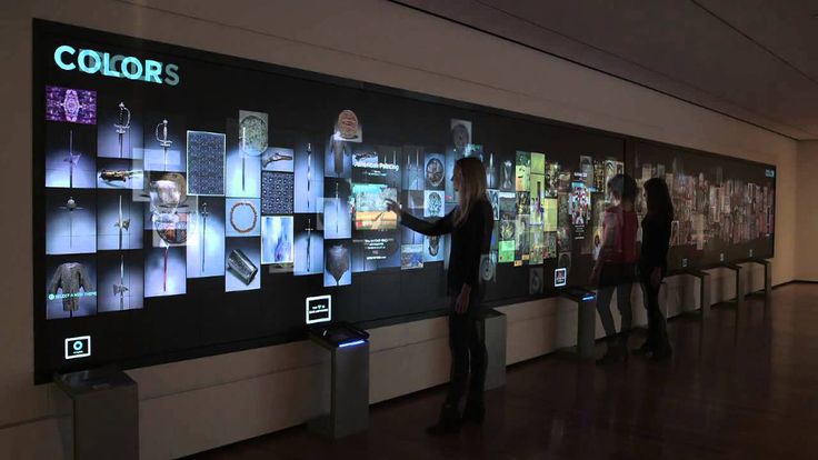
Each variety of flat panel displays (LCD, PDP, and LED) has a number of advantages and disadvantages. With each of the new advanced technologies and finding ways to eliminate shortcomings, manufacturers are trying to accelerate the development and improve the performance of displays so that they can learn how to make medium and large screens. The final goal is to conquer large sales markets, which include television equipment.
Each new improvement expands the potential use of flat panels, increasing competition between manufacturers. For example, liquid crystal panels have literally made inroads into the market for displays up to 40 inches in size. Previously, the production of panels of this size was considered a sector exclusively developed by PDP. Analysts say price competition between LCD and PDP manufacturers will peak by 2003.
Medium to large size OLED panel development has lagged behind comparable class LCD and PDP panels. However, mid-sized OLED panels have been making good progress lately and are continuing at an accelerating pace. This has led to OLED panels displacing LCD technology from applications where it previously dominated. Moreover, OLED and LCD have begun to claim the part of the market where plasma displays have so far reigned supreme.
Meanwhile, the growth of competition between LCD, PDP and OLED allows other technologies to assert themselves. One of the representatives of such technologies is FED (Field emission displays). Recently, manufacturers have taken a huge step forward in the development of FED technology. For example, Sony and Candescent Technologies Corp. co-developed a 13.2″ FED panel with SVGA resolution and 800 cd/m2 brightness. m (!). On the other hand, the Korean company Samsung SDI Corp., Ltd. developed a prototype 3-inch FED panel that uses carbon nanotubes. Company representatives say that if all goes according to plan, mass production of 30-inch FED TVs will begin no later than 2004.
Please note that further improvements to OLED and FED panels may be progressing somewhat faster than anticipated. All formats of flat panel displays would then, in all likelihood, compete with each other in the market for large screens with high image quality.
Velvet — Christie’s High Resolution LED Display
Nicholas Fazio, Christie’s Senior Product Manager, explains the company’s motivation for entering the LED market.
— Why did Christie decide to enter the LED market now?
— Christie has been exploring the possibility of large format LED displays for some time, however, to say that we have only just entered the LED market is not entirely accurate. This technology has found its creative application in Entero LED, the world’s first LED-based imaging system with rear projection and ultra-high resolution support. Of course, we should not forget about MicroTiles, where it is also used.
— Why did you choose high resolution modules for this?
— Because Velvet is designed for fixed indoor applications, we offer a choice of four high-resolution pixel pitch options — 1. 875, 2.5, 3, and 4mm. This achieves optimal image quality when viewed from close and far distances, strictly along the optical axis or at an angle.
— There are many premium high quality displays on the market, so why would Christie come up with an alternative LED solution?
— Customers who needed a widescreen display for use in high ambient light conditions insisted on using LED technology. The new solution has become the missing piece in our product portfolio. We have such a rich selection of visualization technologies that we can reasonably recommend to our customers the products most suitable for their systems. Velvet will be another tool for them.
— What competitive advantage does using Velvet offer? Judging by the pixel pitch and output characteristics, these are very bright high resolution displays.
— Our products have many advantages that set us apart from our competitors. The importance of a high pixel fill rate and an extremely small pixel pitch of no more than 4 mm cannot be underestimated.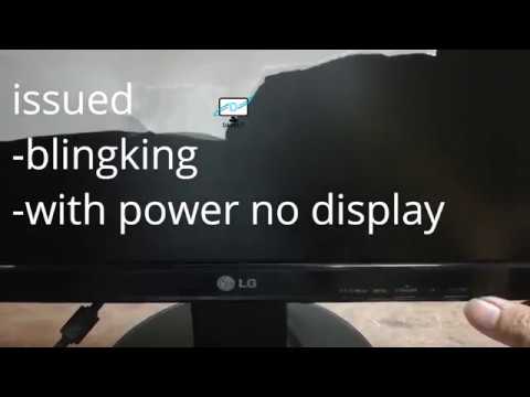 We view this device more as a display than as a digital signage solution. Velvet also supports many specialized content management and processing tools. In particular, the Spyder processor will serve as an excellent addition to it. We were able not only to increase the fill rate, but also to achieve high brightness through the use of large diodes, and also solved the noise problem that is common with some LED displays. In addition, we managed to significantly reduce heat generation. This display heats up only slightly, while others clearly emit heat.
— Your product launch for the EMEA market took place at IBC, the TV Technology Show. What features of Velvet will be beneficial for this particular segment?
— TV studios will have less unnecessary noise because this unit has no fans. It supports a variety of color temperatures ranging from 2700K to 9300K. Broadcast systems are typically tuned up to 3500K.
— What other benefits do these high resolution displays have?
— I have been involved in LED technology ever since researchers were able to overcome the 4mm barrier by reducing the pixel pitch. The Velvet developers have done everything so that the pixelation that occurs when using large pixels does not interfere with viewing the display at close range. Its field of view covers 160°, even if the observer’s gaze is not aligned with the optical axis. We turned to technologies that help maintain a high contrast ratio of 3000:1 and a high brightness of 1000 nits (cd/m2) at the same time.
In addition, many manufacturers use a special mask placed between the elements of the LED display. As a result, if the direction of your gaze does not coincide with the optical axis, you will notice black dots on the display. And when the pixel pitch does not exceed 3 mm, a mask with a back adhesive layer is used, which peels off when heated and degrades image quality. We removed this mask and applied a dark coating to the PCB to keep the contrast ratio high. Now the image looks equally good from any angle.
— What markets do you consider your main ones?
— Released product focused on indoor fixed systems, so our main markets are casinos and museums, retail stores, corporate offices, universities and TV studios.
— You have been with Christie for one year. Tell us about your professional background and your impressions of Christie engineers.
— When I was first contacted by Christie, it was immediately clear that the company had done a thorough research on my background and had a lot to offer. This situation was fine with me. At the first meetings, it seemed to me that Christie has been engaged in LED technology since its inception! I have 14 years of system integration experience under my belt from international projects in China, Europe and the Americas. I have put together an excellent portfolio.
Christie has a huge staff of engineers and researchers at its headquarters in Kitchener. They create highly effective designs based on cutting-edge engineering, as well as extensive testing of integrated circuits for LED drivers, pixels and more.
— Velvet LED modules can be mounted in a wide variety of configurations. What can you tell us about connecting modules to each other?
— There are no limits to the creative combination of modules. The user only needs to daisy-chain power and video to the product. It is possible to design unique curved screens and movable video walls in full compliance with the specified specifications. In addition, this display is lightweight and easy to maintain with minimal maintenance required, and the mounting mechanism used is unique to each installed system. The entire color calibration process takes place at the factory.
— What will be the next evolution of Velvet?
— We have room to grow as new products come out.
— Why would customers go to Christie when the market offers a wide range of choices?
— Because our solutions are highly valued and backed by end-to-end support, while service is provided by local staff around the world. Christie is known as a premium brand, so people come to us with certain expectations. Not every company can boast of such experience.
— Finally, what would you say to your clients about Velvet?
— Velvet is one of the products that the customer doesn’t think about until they see it.![]() All of our work is focused on meeting the needs of Christie’s customers, who receive technical support around the world. This acquisition should not be associated with inconvenience — neither before nor after the purchase. I think that Velvet is a unique development, and it has already caused a storm of enthusiasm.
All of our work is focused on meeting the needs of Christie’s customers, who receive technical support around the world. This acquisition should not be associated with inconvenience — neither before nor after the purchase. I think that Velvet is a unique development, and it has already caused a storm of enthusiasm.
www.christieEMEA.com
Tags:Christie, LED
Why won’t my computer turn on? Reasons, tips, recommendations — Start.RF
Almost everyone had cases when the computer did not turn on. Have you asked or are asking questions like: “Why does the computer not turn on? The computer does not turn on, what should I do? Why won’t the screen turn on? Does it not turn on and beeps? Why won’t the fans turn on? Why does it have a blue or black screen? Why does the computer display a message that there is no video signal when I turn it on?
In fact, there can be a lot of reasons why your computer has stopped turning on. We have prepared for you a comprehensive material that describes the main reasons for which the computer does not turn on, their description and possible actions to fix them.
We hope you find this manual useful. You can ask all questions in the comments on this page and we will try to answer them. If you cannot identify and fix the problem yourself, you can always contact us for free* diagnostics and computer repair services.
We do not bear any responsibility for manipulations performed by you with the software or hardware of the computer in accordance with this manual and do not give guarantees for the restoration of the computer’s performance. Remember that this material was prepared by specialists and computer repair work should be carried out by professionals.
The main symptoms of not turning on the computer
This part contains the main, often common symptoms of not turning on the computer, the actions and sequence of their implementation, by taking which you can bring the computer into working condition.
Basic procedure for when the computer does not turn on. Check:
- Is there voltage in the socket by connecting, for example, a kettle
- Is the power cord connecting the power supply and the socket
- Is the power supply button on the power supply switched on
- Is the computer power button pressed correctly
2 9083 Correctness supply power to the computer monitor
- Is the system unit and monitor connected with a connecting cord
- Open the system unit and perform a visual inspection
- Correct wiring inside the system unit
- Disconnect all peripheral equipment and try to turn it on
- Install a new BIOS battery or disable it temporarily
- Disconnect the video card and all other cards from the PCI slots
- Reconnect the RAM sticks one by one
- Leave only the motherboard, processor and power supply
Performing these recommended actions may lead to the resumption of the working state of your computer. If the above recommendations did not lead to the desired result, then a detailed clarification of the reasons for the computer’s refusal to turn on is required.
Consider the main causes and symptoms why your computer does not turn on
- There is no power in the outlet
Check with the tester that the voltage is correctly supplied to the outlet or plug some other device into the outlet and check whether it will work from it. - Faulty power cord
Checking for a faulty computer power cord is easy enough. It is necessary to measure the correctness of the voltage transfer with a tester on both sides or take another power cord, for example, from a monitor. - The power supply is off
There is a switch on the outside of the power supply. Try switching it to another position and try to find out if this switch is broken. For most power supplies, this switch should make a mechanical switching sound (click) when switched to another position.
- BIOS battery is dead
Each motherboard has a separate firmware (BIOS) that maintains its operation with a button cell battery. If this battery is completely discharged, then the computer may not turn on in some cases. We recommend replacing the battery with a new one. - The RAM sticks have moved
Under external impact on the system unit (shock, movement, vibration), the RAM sticks can move and the computer will not turn on. We recommend disconnecting the RAM and trying to turn it on. Then connect the RAM and try to turn it on again. - Connecting cables are disconnected
Open the cover of the system unit, visually inspect for disconnected wires. Check the security of the wires. - Component failed
Disconnect all additional boards from the motherboard: sound card, TV tuner, video card, Wi-Fi adapters, controllers, etc. Here it is necessary to act by the method of elimination — take out one board, try to turn it on, if the computer turned on when a board was disconnected, then it means that it is in it.
- There is a lot of dust in the computer
When a lot of dust accumulates in the system unit, this can lead to serious consequences, up to and including the failure of all components with the prospect of buying a new computer. If there is a lot of dust, then your computer needs cleaning. - Severe overheating of the processor and / or video card
The processor can heat up to hundreds of degrees in a few seconds. If the computer does not turn on due to the rapid heating of the processor, then you need to replace the thermal paste. Also, dust could get under the processor or it could «move out» (you need to remove the dust and check the correct installation of the processor in the socket). - Broken power button
If the reason for not turning on the computer is a broken power button, then you can check this quite simply. Open the system unit and identify two wires coming from the power button to the motherboard.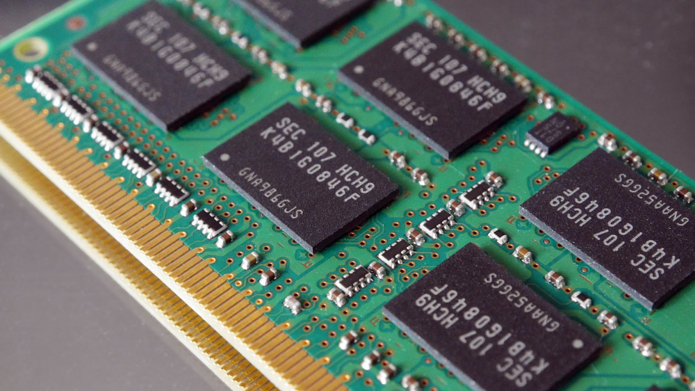 These two wires will be connected with plastic connectors to the motherboard. Disconnect them and short these two contacts with something metallic that passes current. Remember to take precautions when working with voltage.
 - Smell of something burning
If you smell something burning, turn off the power immediately and call a professional. Most often, power supplies burn out. If you are confident and sure that the power supply has burned out, buy a new one and plug it in. - The computer beeps and does not turn on
If a squeak is heard from the depths of the system unit, these are the so-called BIOS beeps about the state of the computer. But what do they mean? — you ask. You can find information about what this or that signal means on our website in the section on signals and BIOS codes. By deciphering the BIOS signal, you can understand what the problem is. Detailed information about the beeps and signals of the BIOS. - Some numbers light up on the motherboard
take certain actions accordingly.
- Peripherals connected incorrectly
There are times when people, due to their ignorance, connect peripheral equipment to the wrong connectors in which it should be connected. Because of this, the computer may not turn on. Disconnect absolutely all external devices (cameras, mice, keyboards, etc.) from the computer and try to start it. - There are smudges and blisters on the motherboard
If you have measured that some part (capacitor) is swollen on the motherboard or noticed strange smudges of an unknown substance, then most likely, at least, you will have to change the motherboard to a new one. - All or some fans do not turn on
Most likely the power supply or motherboard has failed. They need to be repaired or replaced with new ones. We recommend checking the connection of the wires coming from the fans to the motherboard. - The computer turns on and then immediately turns off
There are several reasons for this:- The power supply is out of order and needs to be replaced
- The processor is overheating (thermal paste needs to be replaced)
- The motherboard is faulty (repair or change)
9083 others are faulty accessories (requires diagnostics)
Possible options for not turning on the computer in descending order of probability:
- BIOS settings have gone wrong or the chip has failed
- RAM failure
- The motherboard is faulty
Check the connecting cable between the video card and the monitor, there may be a problem only in this.
 The second option is the video card is out of order. If the video card is separate, then you can try to install another video card and check. If there is also no signal with the new video card, then the monitor is most likely broken.
 The so-called blue screen of death appears due to problems in the operation of component parts, their malfunctions, incompatibilities, dirt and problems in the Windows operating system. A blue screen appears and gives an error code by which you can determine the malfunction and, if possible, eliminate it.
In most cases, a black screen is a symptom of a hardware problem. Often, when the hard drive fails, this very black screen appears, it also appears when the RAM does not work correctly and a number of system files are lost from the hard drive. In this case, diagnostics are required as a result of which the cause of the malfunction will become clear.
If, at some point during the loading of the operating system, the computer starts to restart and the whole process repeats from the beginning, this may be the result of a malfunction of the operating system or a malfunction of the hard drive. You can try to restore the state of the operating system to an earlier date. A hard drive can have two problems — physical and logical. The logical one can be eliminated with the help of software, and the physical one only with the help of mechanical repair. If the hard drive is physically defective and there is really valuable information on it, then you can restore it, but we do not recommend using such a hard drive later.
If you turn on the computer and the operating system does not boot and you hear quiet or loud clicks inside the system unit, then the hard drive is most likely broken.
 As a rule, physically broken hard drives are not used after repair, since the reliability of their operation can be extremely low.
 If the computer does turn on, but the operating system takes a very long time to load, then most likely this may be evidence of logical or physical malfunctions of the hard drive, as well as evidence of a large number of errors in the operation of the operating system. In case of errors in the operation of the OS, software prevention of its operation is required. Sometimes the computer slows down due to overheating of components.
Supplement #1
Additional reasons for not turning on the computer. Yes, we sometimes update and supplement the material to make it even more useful. If you didn’t find what you need above, you can find it below. And if you have come across some case that is not described here, then its description by you in the comments to the article will be useful to other people.
- The processor is broken
The processor could burn out due to overheating. It is sometimes impossible to notice this visually — as if nothing had happened to him. You need to see if the cover has come off, if it smells burnt, if there are burnt areas, test it on another computer or install another processor (working) in the computer for testing. It is also worth checking carefully whether all the legs are intact. - Chipset
Due to overheating, ingress of foreign objects (dust, thermal paste), rough mechanical impact, voltage drop, short circuit and other reasons, the chipset may fail. You need to carefully remove the processor and visually check for damage. The chipset, like some processors, has legs — inspect them for curvature. - BIOS Firmware
Malware or power surges may have corrupted the BIOS firmware, preventing the computer from turning on normally. It is not possible to check whether the motherboard BIOS is working correctly for an ordinary person (not a master) at home — you need equipment (programmer), pullers, specialized software, knowledge and experience.
- Overclocked processor and unlocking
Due to improper overclocking of the processor, the computer may also not turn on. If the processor is overclocked and there is access to the BIOS settings, then you can play around with the settings for FSB, RAM frequencies, memory timings, multipliers, voltages, etc. If there is no access, then you can try: a) disconnect the BIOS battery; b) disconnect the jumper (jumper) on the motherboard; c) carefully study the options for canceling overclocking in the instructions for the motherboard. - Incompatible software (drivers)
After installing or updating various software, the system may not work correctly. Most often, this is due to driver failures, with the exception of cases of malicious code. In this case, you can try to boot the system in safe mode and remove the previously installed software. An alternative is to restore the system through a system image, but that’s a different story.
- Motherboard has a short circuit
If the motherboard is loose, not fixed correctly, or there is a conductive foreign object between it and the case or other component, for example, an ordinary screw, then there are often short circuits. Inspect the system unit for foreign objects. - Reboot and Select Proper Boot Device. system files. There are other reasons, and there are many. We recommend that you find an article about this on our website, everything is chewed in it to the smallest detail.
- Malicious code
Malicious code can do almost anything to a computer — from a simple joke to the destruction of component parts. If the computer somehow reacts, then we recommend loading a virtual OS or connecting disks to a working system and checking the integrity of the OS files, as well as the presence of malicious code. - Lack of power supply
Power supplies «land out» over time (lose their former power reserve). And if everything worked fine before, and over time the PC began to turn off sometimes or you installed a new component and the PC does not start with it, then this is one of the signs of a lack of PSU power. It is worth determining the required amount of energy consumption of all iron and comparing it with the power of the power supply, including measurements by the tester.
 - Oxidation
Due to high humidity and liquids, component parts are oxidized and this is visible to the naked eye (oxides, darkening). If there are noticeable traces of oxidation (minor) on the motherboard, RAM connectors, video card and other parts, you should get rid of them and then, perhaps, the computer will start and work normally again. If traces of oxidation are significant, then only an experienced person should deal with their elimination. - Does not turn on after a thunderstorm, power outage
If there was a thunderstorm and the PC does not turn on after it, then in 99% of cases this is a hardware failure. Which one exactly? — Anything can burn, but most often power supplies and motherboards fail. If the PC does not turn on after a power outage, then the power supply and other components could fail, and BIOS settings and hard drive files could also be damaged.
 - Will not turn on after a long period of inactivity
With a long idle time connected or not connected, the options can be something like this: oxidation of parts (needs to be cleaned), the BIOS battery has run out (change), the fuse has blown (when connected to the mains), dust has got into unnecessary places (clean), the capacitors are depleted, one of the boards has dried up (it happens with a very long downtime). There are other situations as well. - Freeze, reboot and no longer turn on
This option is one of the most frequent. Most often, the computer freezes due to hardware problems caused by a variety of reasons: malicious code, increased long-term load, system kernel errors, faulty third-party software, OS updates, power surges, and many other reasons. We advise you to use the recommendations at the beginning of the page, read the article itself and the comments to it.
We hope that this material will be useful and help you understand the main reasons why the computer does not turn on. Ask us questions in the comments. We will try to answer you. If you have neither the time, nor the desire, nor the experience to sort out these reasons on your own, you can always contact us for qualified assistance by phone +7 (926) 911-2727 during business hours or leave a request through the website around the clock.
Attention! We are often asked the same questions for various reasons — they don’t read the article or comments, but everything in them has long been sorted out. If you ask a question in the comments, and the answer to it, even if partially, is already on the page, then we will most likely ignore such a question — leave it unanswered.
Call back
Your name
Your phone
What is your problem?
We’ll call you back in 20 minutes
I agree with the rules of the site, including the personal data processing policy
Call the master
Your name
Your phone number
Your address
What is your problem?
We will call you back in 20 minutes
I agree with the rules of the site, including the personal data processing policy
Free consultation
Your name
Your phone
What would you like to ask?
We will call you back in 20 minutes
I agree with the rules of the site, including the personal data processing policy
Order a product or service
Your name
Your phone number
What do you want to order?
We will call you back in 20 minutes
I agree with the rules of the site, including the personal data processing policy
Order a product or service
Your name
Your phone number
What is your problem?
We’ll call you back in 20 minutes
I agree with the rules of the site, including the personal data processing policy
Need help?
Enter your phone number and click Submit.