Identifizieren der verschiedenen PCI-Steckplätze | LaCie Support Deutschland
Identifizieren der verschiedenen PCI-Steckplätze
Peripheral Component Interconnect oder PCI ist eine häufige Methode zum Anschließen von Zusatz-Controller-Karten und anderen Geräten an ein Computer-Motherboard. Diese Art Konnektor stammt aus den frühen 1990er Jahren und wird heute noch verwendet. Derzeit gibt es drei wesentliche PCI-Motherboard-Konnektoren (meist als „Slots“ oder Steckplätze bezeichnet.)
- 64-Bit-PCI
- 32-Bit-PCI und PCI-X
- PCI-Express (PCI-E)
Jeder PCI-Steckplatz sieht anders aus und akzeptiert andere Geräte. Wird eine PCI-Karte an den falschen Steckplatz gesteckt, wird die Karte beschädigt und eventuell wird der gesamte Computer zerstört.
64-Bit-PCI:
LaCie stellt keine Produkte mehr her, die mit diesem Steckplatz kompatibel sind. Für PCs wurden sie meist nicht verwendet, aber für alle G4 und G3 Macintosh-Computer. Dieser Steckplatz kann anhand der drei Segmente identifiziert werden, wobei sich das kürzeste Segment in der Mitte befindet.
32-Bit-PCI und PCI-X:
LaCie stellt verschiedene Erweiterungskarten her, die diesen Konnektor verwenden. Der Unterschied zwischen dem normalen 32-Bit-PCI-Steckplatz und dem PCI-X ist der mittellange Steckplatz auf der linken Seite. Nur PCI-X hat dieses letzte Segment. Zusätzlich funktionieren 32-Bit-PCI-Karten an einem PCI-X-Steckplatz, PCI-X-Karten funktionieren jedoch nicht an einem Standard-32-Bit-PCI-Steckplatz.
Nahezu alle PC-Motherboards haben mindestens den 32-Bit-PCI-Steckplatz. Macintosh G5 verwendete PCI-X bis zur Änderung auf flüssigkeitsgekühlte Hardware-Versionen. Apple kann eine G5-Seriennummer nachschlagen, um zu bestimmen, ob PCI-X-Steckplätze zur Verfügung stehen oder ob stattdessen die neue PCI-E verwendet werden muss.
Diese Steckplätze können vom 64-Bit-PCI anhand der Anordnung der Segmente unterschieden werden.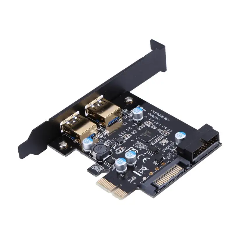 Das kleine Segment kommt an erster Stelle statt in der Mitte.
PCI-Express (PCI-E):
Die meisten Computer, die nach 2005 hergestellt wurden (einschließlich Macintosh), verfügen über PCI-E-Steckplätze. Diese sind manchmal schwer zu identifizieren, da die Länge des Steckplatzes unterschiedlich sein kann. Diese Varianten werden „Lanes“ genannt und sind meist mit einer Nummer, gefolgt von einem x (1x 8x 16x usw.), bezeichnet. In der Abbildung ist ein 16x-PCI-Steckplatz dargestellt. Ein 1x-Steckplatz beginnt mit demselben kleinen Segment, gefolgt von einem zweiten kleinen Segment. Mehrere Lanes bedeuten im Allgemeinen eine größere Schnittstellengeschwindigkeit. Die meisten PCIx-Karten sind 1x oder 4x (mit Ausnahme der Video-Controller, die fast immer 16x-Karten sind.)
Eine 1x-PCI-E-Erweiterungskarte passt in einen 16x-Steckplatz. Aufgrund der physischen Größe bleibt der Rest des Steckplatzes unbelegt, dies ist jedoch normal.
Dieser Steckplatz kann von anderen (insbesondere 32-Bit-PCI) durch seine physikalische Größe unterschieden werden. Alle Konnektoren an einem PCI-E-Steckplatz sind deutlich kleiner und er wird weiter in das Motherboard eingesteckt als andere PCI-Steckplätze.
Matrox Guide to Different Types of Expansion Slots and Add-In Cards
Potential Bandwidths of PCI and PCIe
The higher potential bandwidth that certain slot types provide don’t necessarily result in proportionally higher performance. The bandwidth associated with each slot type is the maximum achievable and is subject to limitations due to software overhead (for example, operating system activity) and whether an application is maximizing usage. For example, a simple 2D application like a spreadsheet or word processing program is less likely to benefit from the advantages of this higher bandwidth. Intensive, real-time, 3D programs are more likely to use such extra bandwidth.
The differences in these bandwidths only affect the speed at which data is transferred between the graphics hardware and the rest of the computer. These bandwidths don’t affect the speed of the graphics chip itself and don’t directly affect the speed of the rest of the computer.
The PCI Express specification also defines backward-compatibility between PCI Express devices. That is, a device designed for Gen-3 PCI Express functions at Gen-2 speeds when connected to a Gen-2 device, a Gen-2 device functions at Gen-1 speeds when connected to a Gen-1 device, and so on.
The following summarizes the differences in potential bandwidth between the various slot types.
| Link width* | PCI-e Gen-1 | PCI-e Gen-2 | PCI-e Gen-3 |
|---|---|---|---|
| x1 | 250 MB/s | 500 MB/s | 1 GB/s |
| x4 | 1 GB/s | 2 GB/s | 4 GB/s |
| x8 | 2 GB/s | 4 GB/s | 8 GB/s |
| x16 | 4 GB/s | 8 GB/s | 16 GB/s |
-
The link width provides a measure of the data transfer capabilities of the link in a single direction.
 Since each PCI Express lane contains both an upstream and a downstream link, the effective bandwidth is doubled. The numbers in this table represent the maximum bandwidth available in each direction.
 -
While the serial data rate has only increased from 5 Gb/s to 8 Gb/s over second generation PCI Express, the encoding of the serial data has changed, providing more efficient transfers and effectively doubling the data transmission rate over Gen-2 PCI Express.
PCI Express® Bandwidth Considerations When Capture Cards and Graphics Cards are in the Same System
Although the input resolutions and formats must be considered, the system bus-level architecture also plays an important role in optimizing the system for the best possible performance.
Input source bandwidth requirements
Any capture architecture receives its data from external sources and transfers it to one or more graphics engines for display.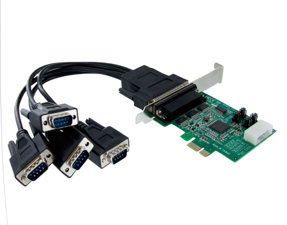 The inputs may take many forms: IP, DisplayPort, HDMI, DVI, analog RGB, component video, or even standard TV inputs using either composite or Y/C signals. Each of these inputs places a different load on the system in terms of quantity of data to be transferred.
The bandwidth required to transfer a captured stream within a computer system is dependent on input resolution, format and frame buffer organization. The input format refers to both pixel depth (8- or 10-bits) and pixel format (4:4:4, 4:2:2 or 4:2:0), and frame buffer organization is typically linear or planar. Although a frame buffer may be 24 bits, system transfers are performed in 8-, 16-, or 32-bit «chunks». The formula below provides an approximation of the bandwidth required from a given input stream, and assumes planar frame buffer organization.
In some cases, it may be possible to capture sources and transfer them internally using a 16-bit YUV format. Doing so will reduce the amount of system bandwidth required to transfer the input data, but it will also degrade the capture quality (since less data is being used to represent each pixel).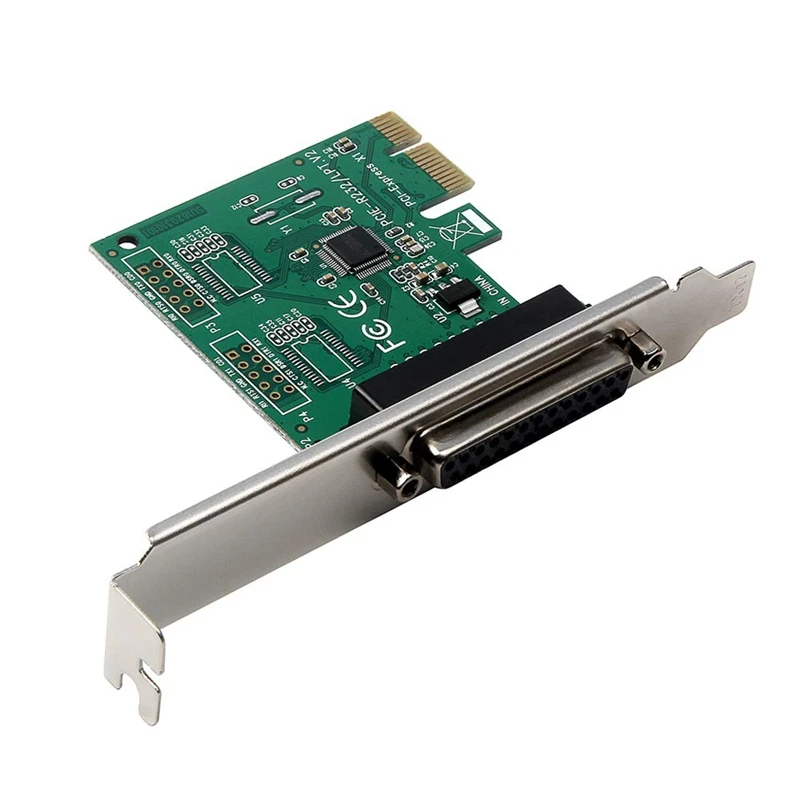 This option should be used only when necessary, and with sources, where the quality of input capture can be sacrificed. The bandwidth required by any input source can be expressed as follows:
BW = resx x resy x fps x kpixel_factor
Where fps and kpixel_factor represent the number of frames per second and the number of bytes taken by each pixel, respectively. In analog RGB, component and DVI modes each pixel generally requires 4 bytes. In TV modes (or when data is represented as 16-bit YUV data) each pixel requires 2 bytes.
The table below provides a summary of pixel factors for different pixel depths and pixel formats.
| 4:4:4 | 4:2:2 | 4:2:0 | |
|---|---|---|---|
| 8-bit | 4 | 2 | 1.5 |
| 10-bit | 6 | 4 | 3 |
For example, a high-definition source being captured at 1920×1080p60 requires the following bandwidth:
BW 1080p = 1920 x 1080 x 60 x 4 ≈ 500 MB/s
An NTSC source at 60 Hz (interlaced) requires the following bandwidth:
BW NTSC = 720 x 480 x 30 x 2 ≈ 21 MB/s
Here are some examples of approximate bandwidths based on resolution/pixel formats:
| 4:4:4 | 4:2:2 | 4:2:0 | |
|---|---|---|---|
| 8-bit | 1000 MB/s | 500 MB/s | 375 MB/s |
| 10-bit | 500 MB/s | 250 MB/s | 185 MB/s |
For more information on video sampling and formats, see the following resources:
-
Recommended 8-bit YUV formats for video rendering
-
10-bit and 16-bit YUV video formats
Regardless of the resolutions and formats of the various inputs, the available system bandwidth shouldn’t be exceeded.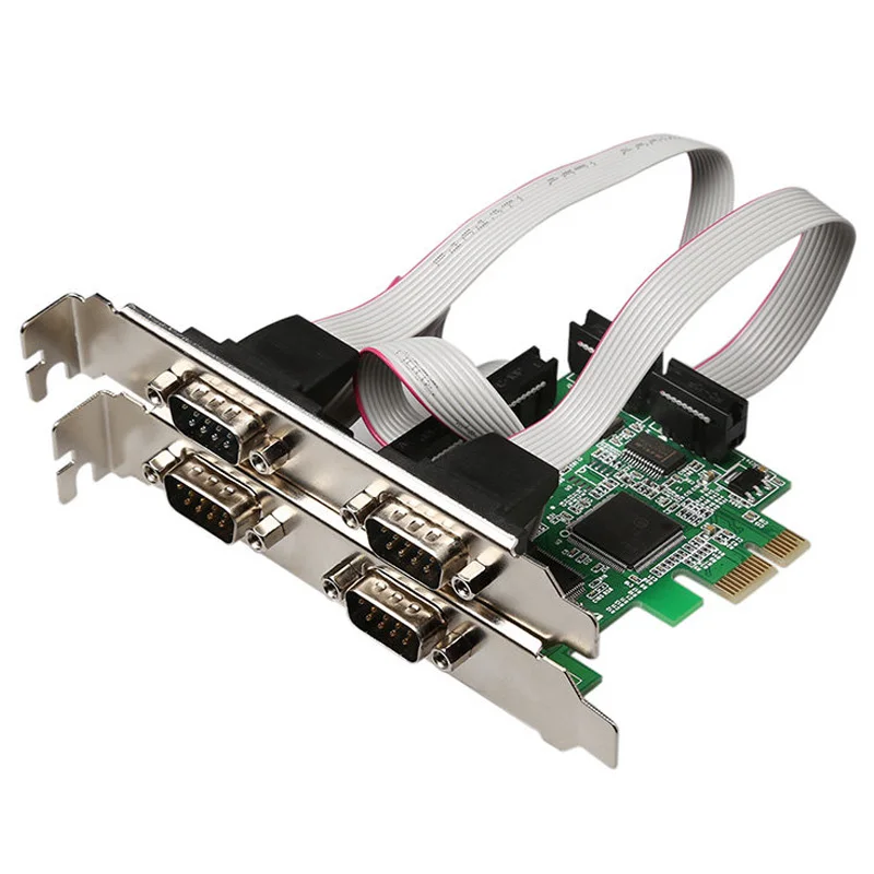 Doing so will result in reduced system performance and/or instability.
PCI Express architecture overview
To understand how system architecture plays a role in the available bandwidth, a basic understanding of the PCI Express architecture is helpful. This section provides a brief description of the PCI Express architecture to provide enough background to understand the bandwidth calculations provided later in this discussion.
To maximize data transfer capabilities within a system, having the largest lane widths possible throughout the system is preferred.
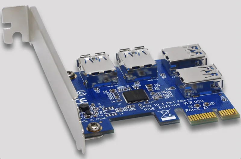
Communication cards with PCI Express bus
Privacy and Cookie Information:
This website uses cookies for tracking visitor behavior, for linking to social media
icons and display videos. More information on how we deal with your privacy, please check our
Privacy & Cookies Statement.
Please remember that if you do choose to disable cookies, you may find that certain sections of our website do not work properly.
- Products /
- Smart Grids /
- Serial / USB Communications /
- Serial communication cards /
- Communication cards with PCI Express bus
PCI Express is a very popular hardware interface used on a variety of computing platforms, and its high data transfer speed and bandwidth make it ideal for automation applications. Advantech has used its years of experience in the field of industrial automation to offer the most reliable and high performance PCI Express serial interface boards. These boards are designed to connect various high performance
Continue Reading
-
PCE-GIGE
PCI Express x4, 2/4-Port GbE Expansion Card
View Product
-
PCE-GIGE4
Ethernet card with 4 GbE ports (PCIex4)
View Product
-
PCE USB
PCI Express x4, 4-Port USB 3.
 0 Expansion Card
 View Product
-
PCIE-1602
2-port RS-232/422/485 PCIe Communication Card w/Surge & Isolation
View Product
-
PCIE-1604
2-port RS-232 PCIe Communication Card w/Surge & Isolation
View Product
-
PCIE-1610
4-port RS-232 PCIe Communication Card w/Surge
View Product
-
PCIE-1612
4-port RS-232/422/485 PCIe Communication Card w/Surge & Isolation
View Product
-
PCIE-1620
8-port RS-232 PCIe Communication Card
View Product
-
PCIE-1622
8-port RS-232/422/485 PCI Express Communication Card
View Product
-
PCIE-1672PC
2-port 10/100/1000 BaseT(X) 802.
 3af (PoE) Compliant Ethernet ports, PCI Express Communication Card
 View Product
-
PCIE-1674PC
4-port 10/100/1000 BaseT(X) 802.3af (PoE) Compliant Ethernet ports, PCI Express Communication Card
View Product
- Request for Quote
Contact Advantech
8-800-555-01-50
8-800-555-81-20
PCI Express
The PCI Express interface, also known as PCIe, has been the I/O bus standard for computers in recent years. The first version of the PCIe 1.a specification was introduced in 2003. Version 2.0 appeared in 2007, version 3.0 in 2010. Specification versions are also called generations.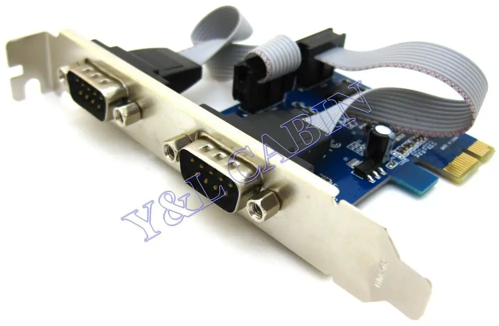 It usually takes a year or two from the moment the specification is introduced to the moment when computers and devices using the new version of the interface are widely used. The PCIe specifications are developed and maintained by the PCI-SIG organization. PCI Express and PCIe are registered trademarks of PCI-SIG. The development of passing SATA and SAS traffic over PCIe connections is in full swing.
Refer to the table below for the baud rates of the various PCIe versions. They are expressed in gigatransactions per second (GT/s) and are functions of the number of lanes on the link. PCI Express supports full duplex data transfer mode (information flow can go in two directions at the same time). The baud rates in the table are for unidirectional transmission.
| GT/s | Coding scheme | x1 | x2 | x4 | x8 | x16 | |
|---|---|---|---|---|---|---|---|
| PCIe 1.x | 2.5 | 8b/10b | 250 MB/s | 500 MB/s | 1 GB/s | 2 Gb/S | 4 Gb/S |
PCIE 2.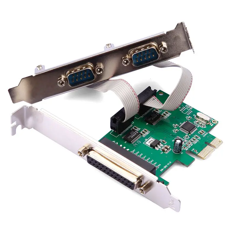 x x |
5 | 8B/10B | 500 MB/S | 1 GB/S | 2 GB/S | 8 GB/s | |
| PCIe 3.x | 8 | 128B/130B | 1 GB/S | 2 Gb/S | 4 GB/S | 8 GB/S | 16 GB/S |
Mini-PCIE
9ATHERS mini-PCIe form factor. This is a form factor specially designed for portable computers, measuring approximately 30x51mm or 30×26.5mm. Mini-PCIe is equivalent to a single-lane PCIe connector. Many devices such as WiFi modules, WAN modules, video/audio decoders, SSD drives, etc. are available in this form factor.
M.2
M.2 is a new generation of PCIe connector for ultra thin mobile devices. M.2 supports PCIe and SATA protocols, but not both. Many cards of various widths and lengths are supported. M.2 is available as a single-sided module that can be soldered onto the card, or as a single-sided and dual-sided module used with a connector.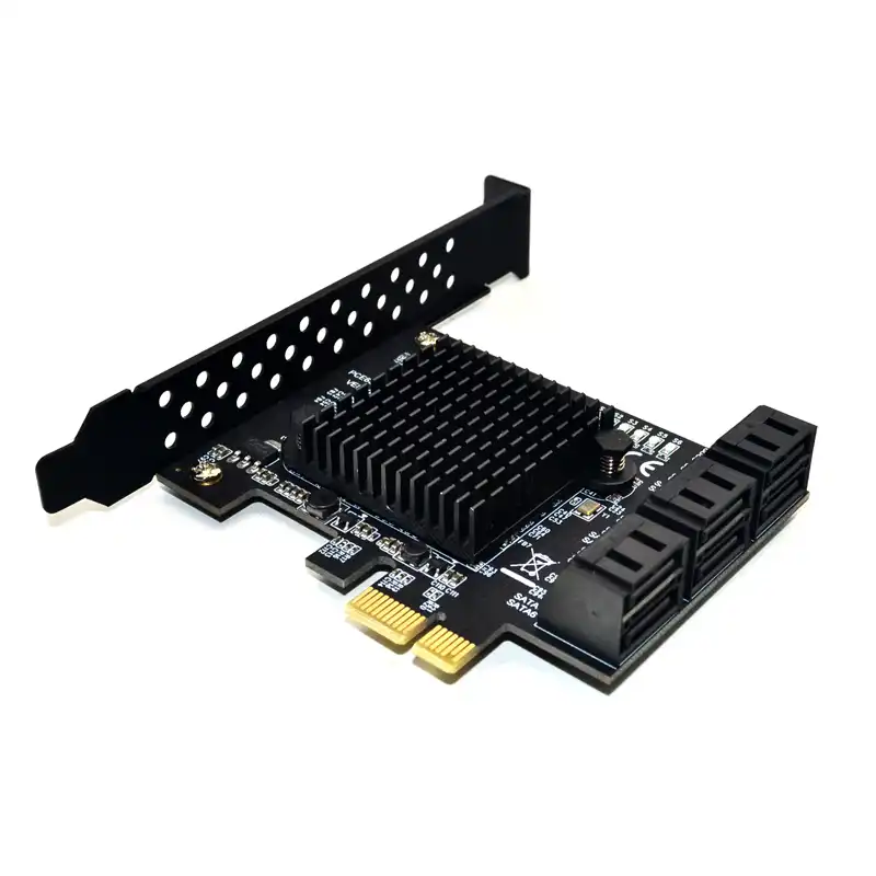
U.2 (SFF-8639)
U.2 (known as SFF-8639 until June 2015) is an I/O backplane connector designed for high-density SSD storage devices and is compatible with existing interfaces. SFF-8639supports PCIe/NVMe, SAS and SATA devices and allows hot plugging and swapping of devices while the system is running.
M-PCIe
M-PCIe is a specification that maps PCIe to MIPI Alliance M-PHY technology used in low power mobile devices. M-PCIe is RFI/EMI optimized and supports M-PHY 1, 2 and 3, M-PHY 4 is expected. with one adapter.
PCIe 3.0
On March 6, 2012, server hardware manufacturers announced a new generation of PCIe 3.0-enabled servers that, among other things, had twice the I/O bandwidth of the previous generation. These servers support up to 40 PCIe 3.0 lanes per processor socket, which is at least twice as many lanes as previously available. Workstation and home computer motherboards supporting PCIe 3.0 first appeared at the end of 2011, at the same time the first PCI Express 3.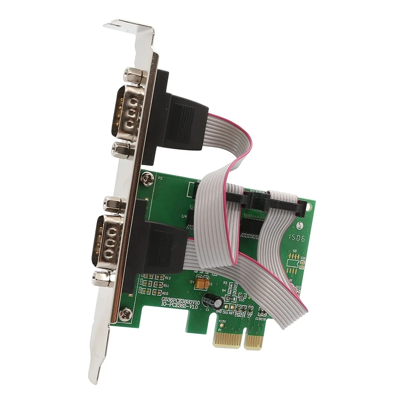 0 graphics cards appeared.
PCIe 3.1
The PCIe 3.1 specification was released in October 2014. It includes M-PCIe and consolidates many protocol and functionality extensions for ease of use.
PCIe 4.0
In November 2011, the PCI-SIG confirmed that the next generation of PCIe called PCIe 4.0 will have data transfer rates of 16GT/s. Technical analysis has established that known technologies allow the creation of a new interface with a specified data rate. The new standard will be backward compatible with PCIe 1.x, 2.x and 3.x. Version 0.5 of the PCIe 4.0 specification expected in mid-2015, version 0.9will be available in the second half of 2016. After the specification is finalized, it will take about a year or more for PCIe-based products to appear.
OCuLINK
OCuLINK is an inexpensive small form factor cable for connecting internal and external devices such as storage devices or graphics cards. Passive cables up to 3 m and active copper and optical cables provide data transfer rates from 8 Gbps with a margin for increase.